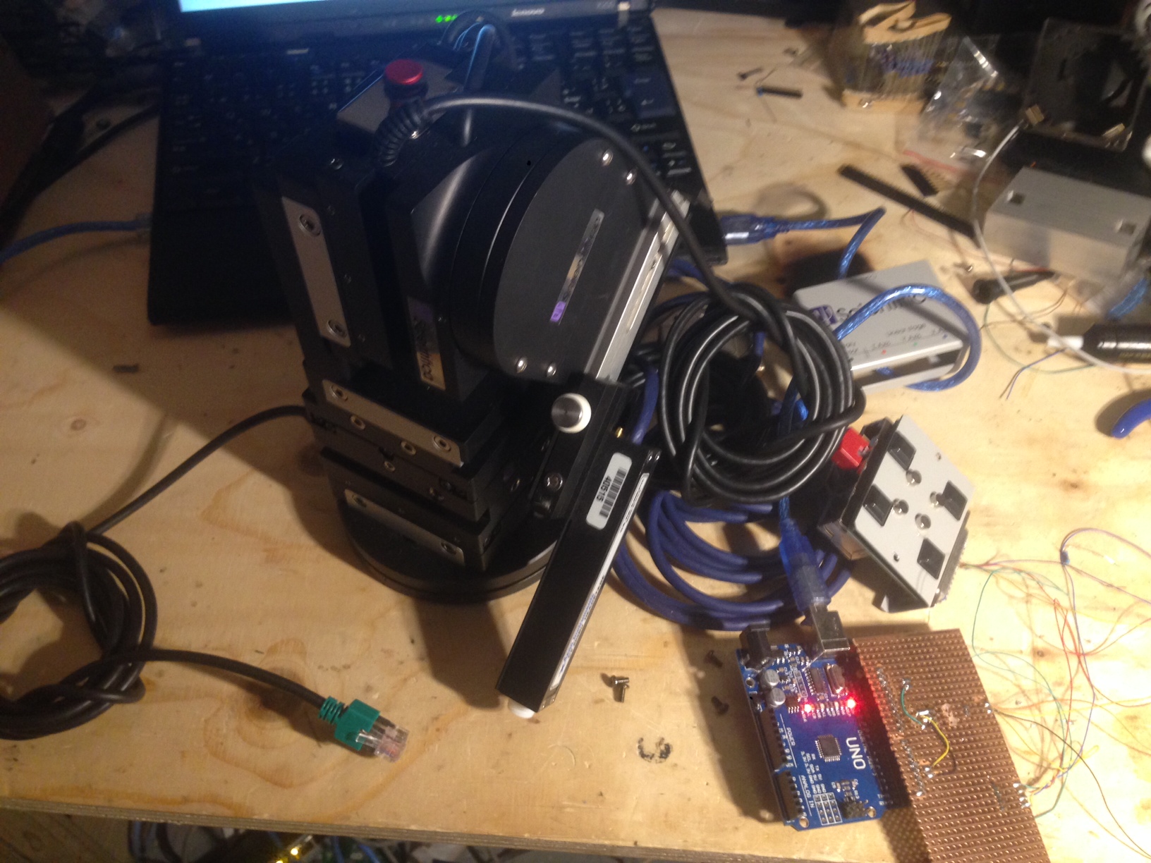
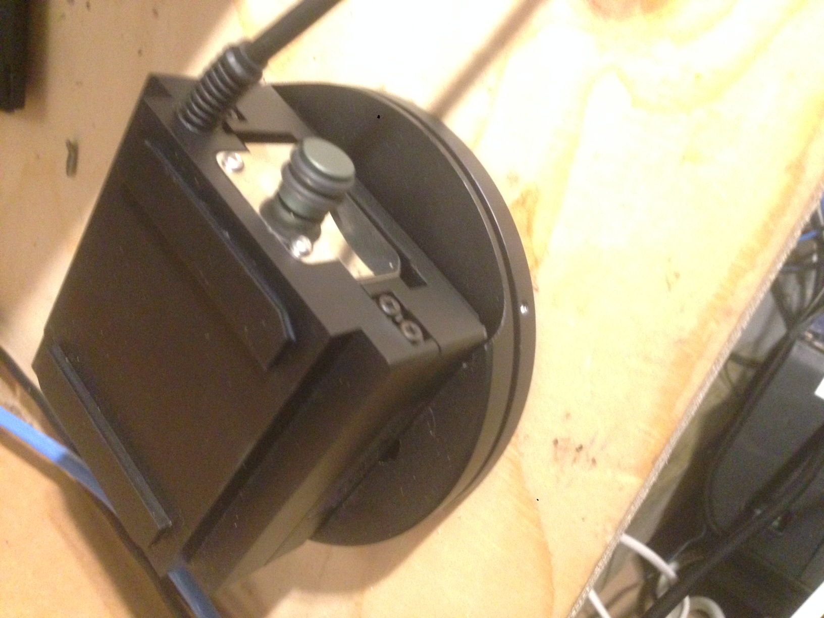
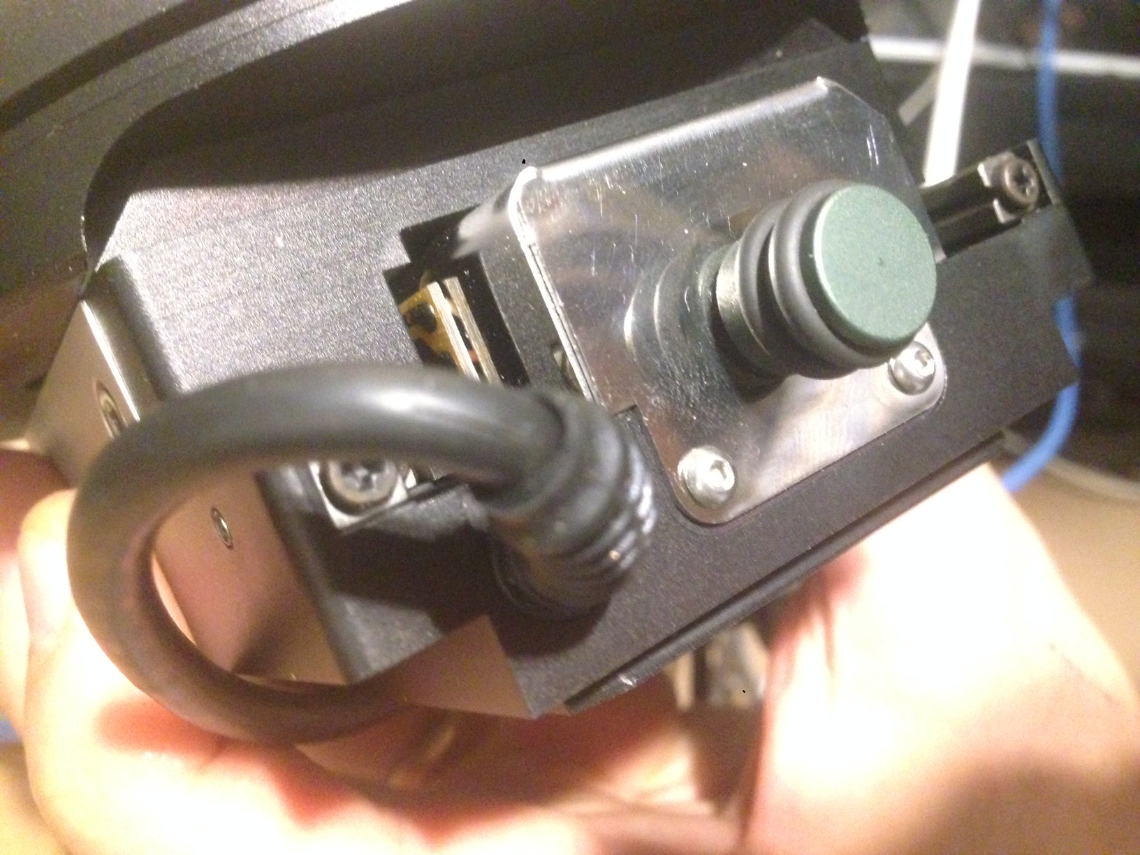
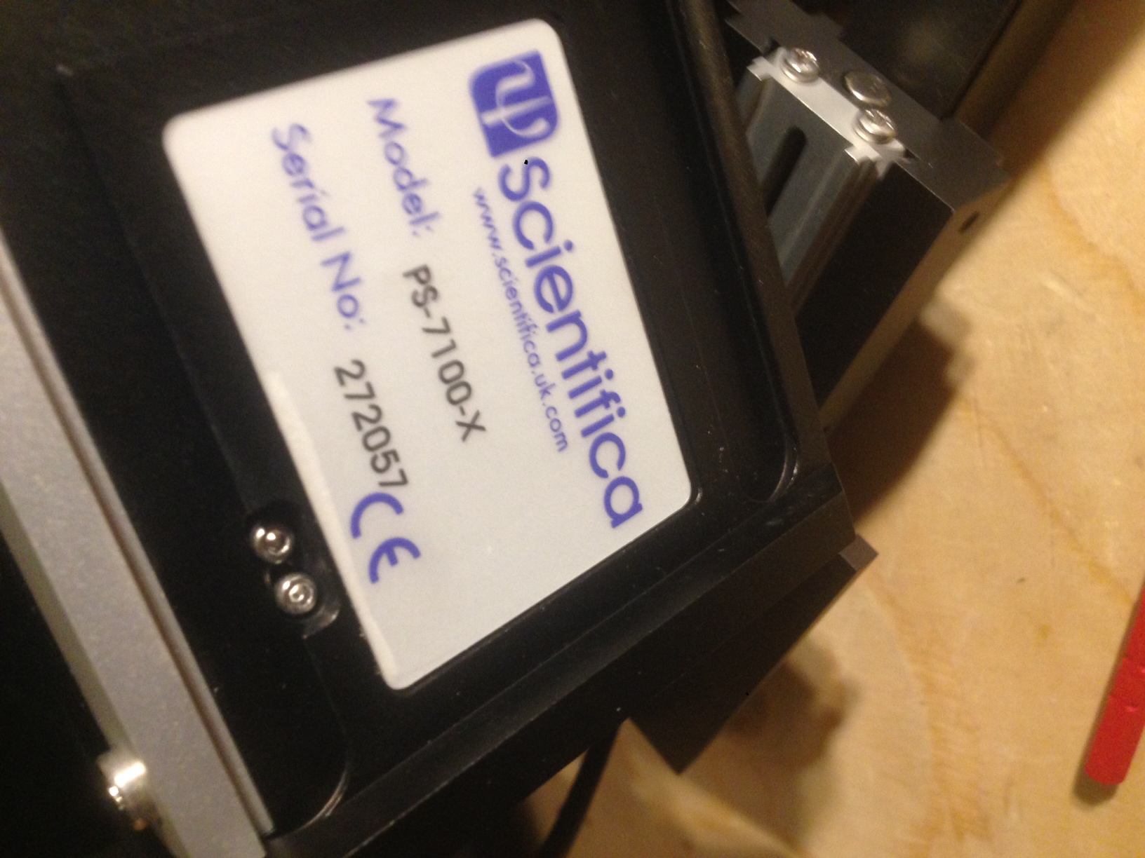
I’ve been playing with a Scientifica Patchstar. The Patchstar is a patchclamp manipulator. It has a claimed electronic resolution of 20nm which is pretty impressive but I think that’s just the step size.
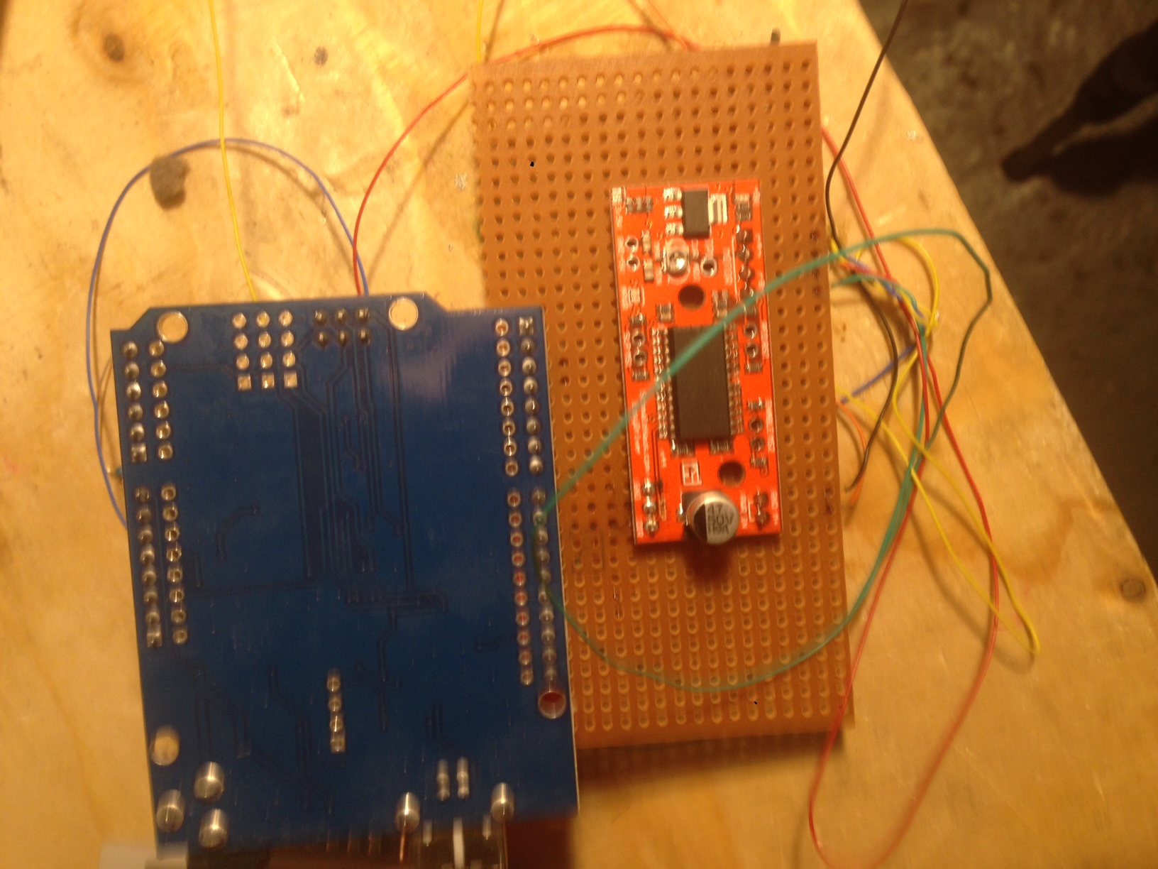
Unfortunately I don’t have the driver, and a new one would cost about 1500USD. However it appears to just use bipolar steppers and operates with an Arduino and a Easydriver quite easily. From the travel I get from the EasyDriver it looks like it would need to use 256 microstepping. I’ve purchased some drivers to try this out at some point.
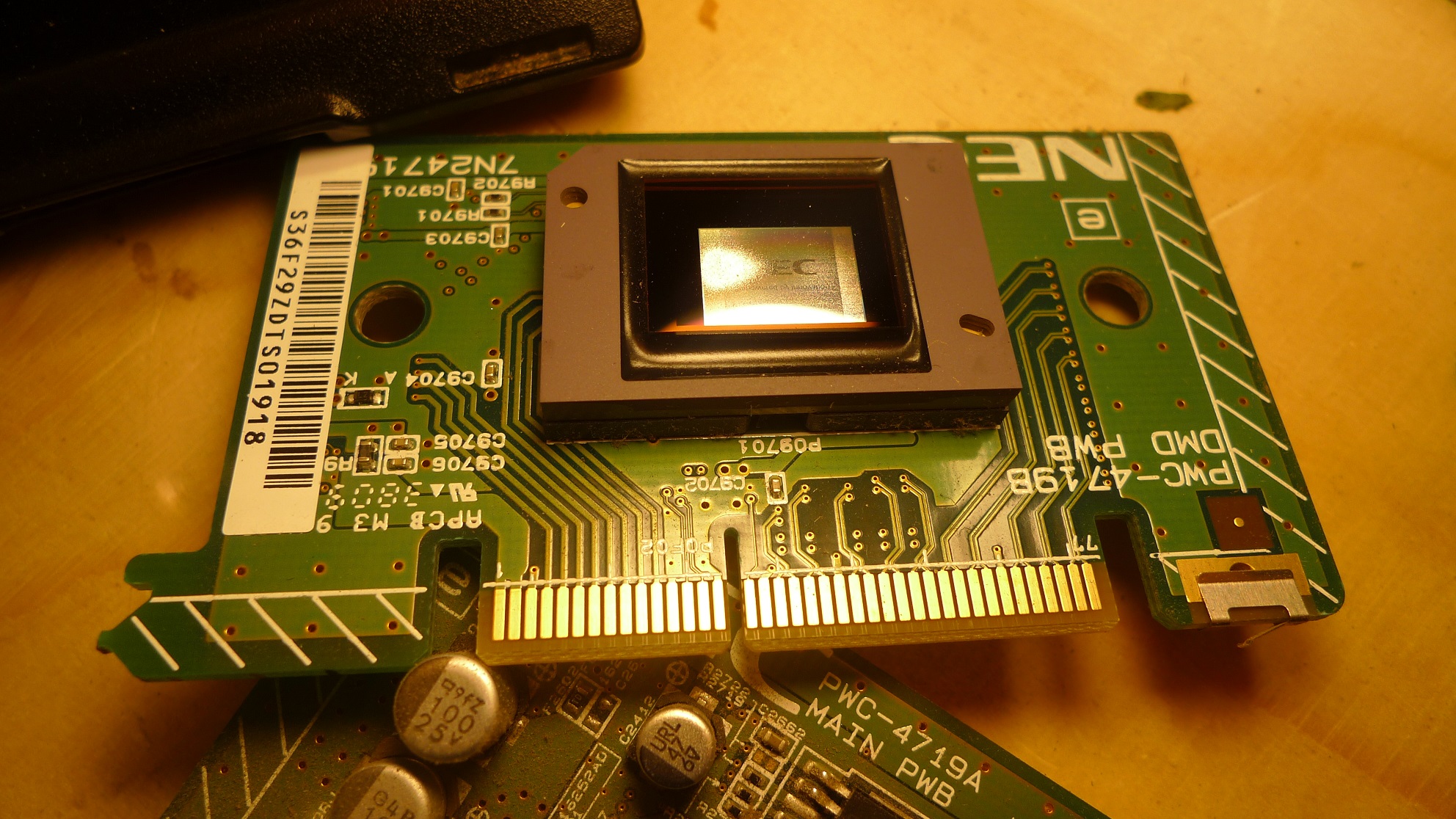
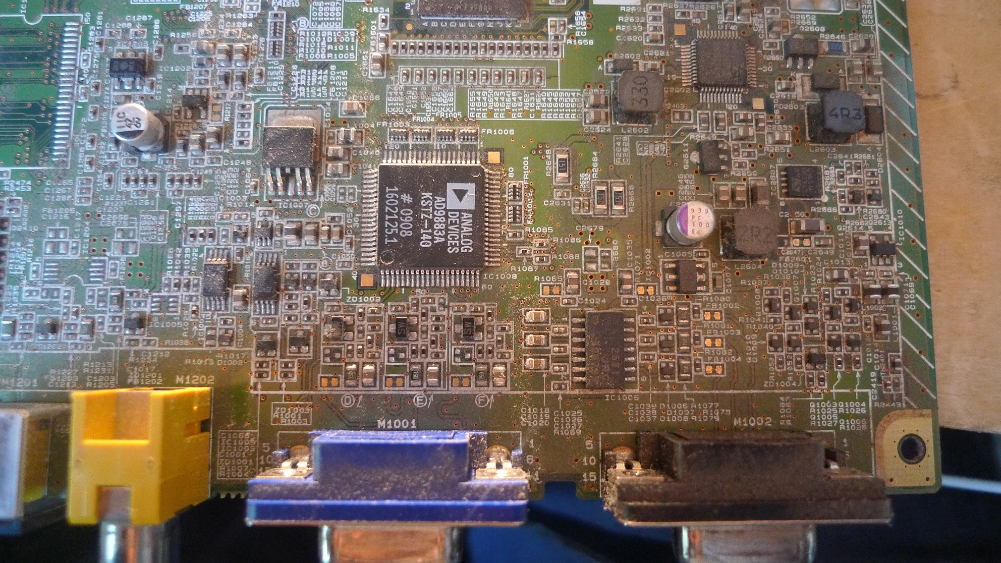
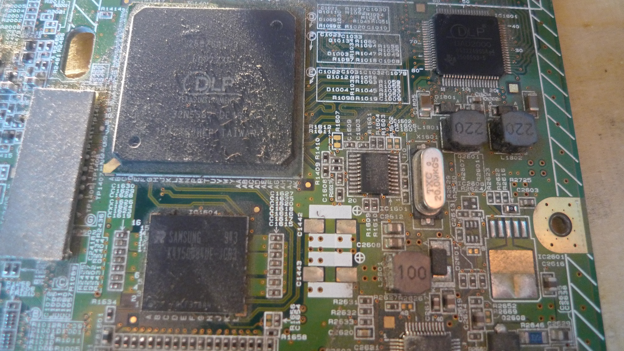
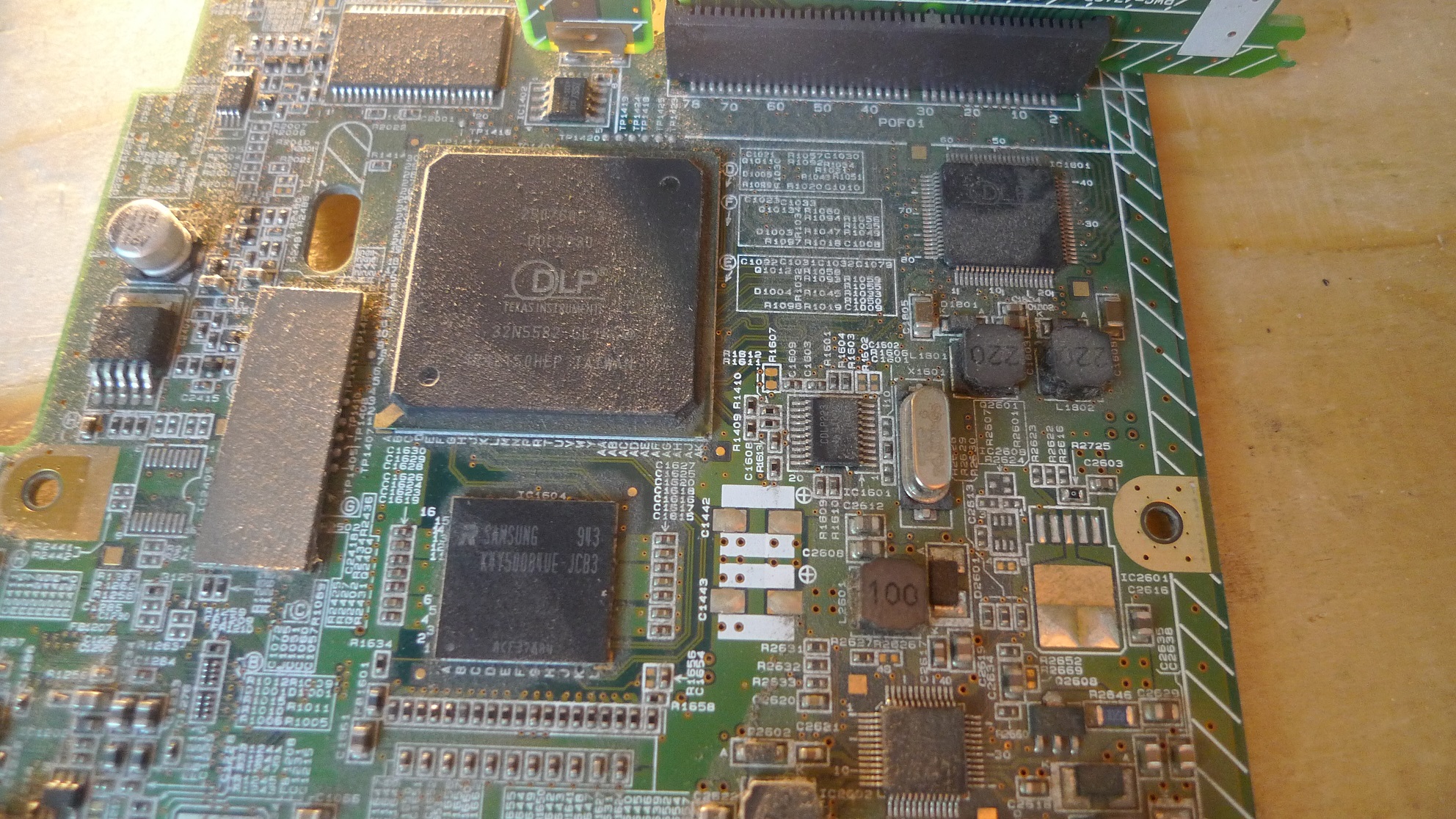
I’ve been playing with an old, faulty NEC Projector. It uses a DDP2230 DLP controller, for which no datasheet is available. It took a bit of fiddling to get everything working out of the case and the mercury lamp burnt a nice mark in my desk… I did manage to get some video of the DMD (1076-6039b IIRC) working:
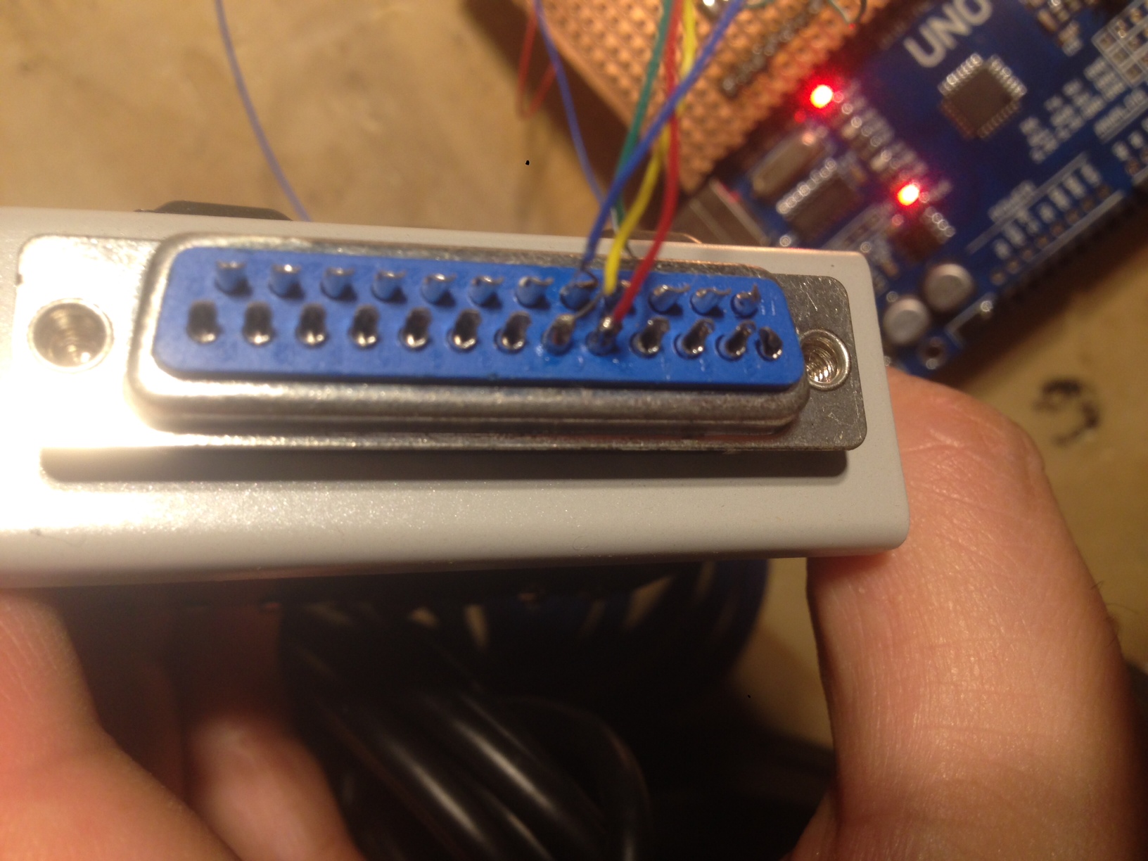
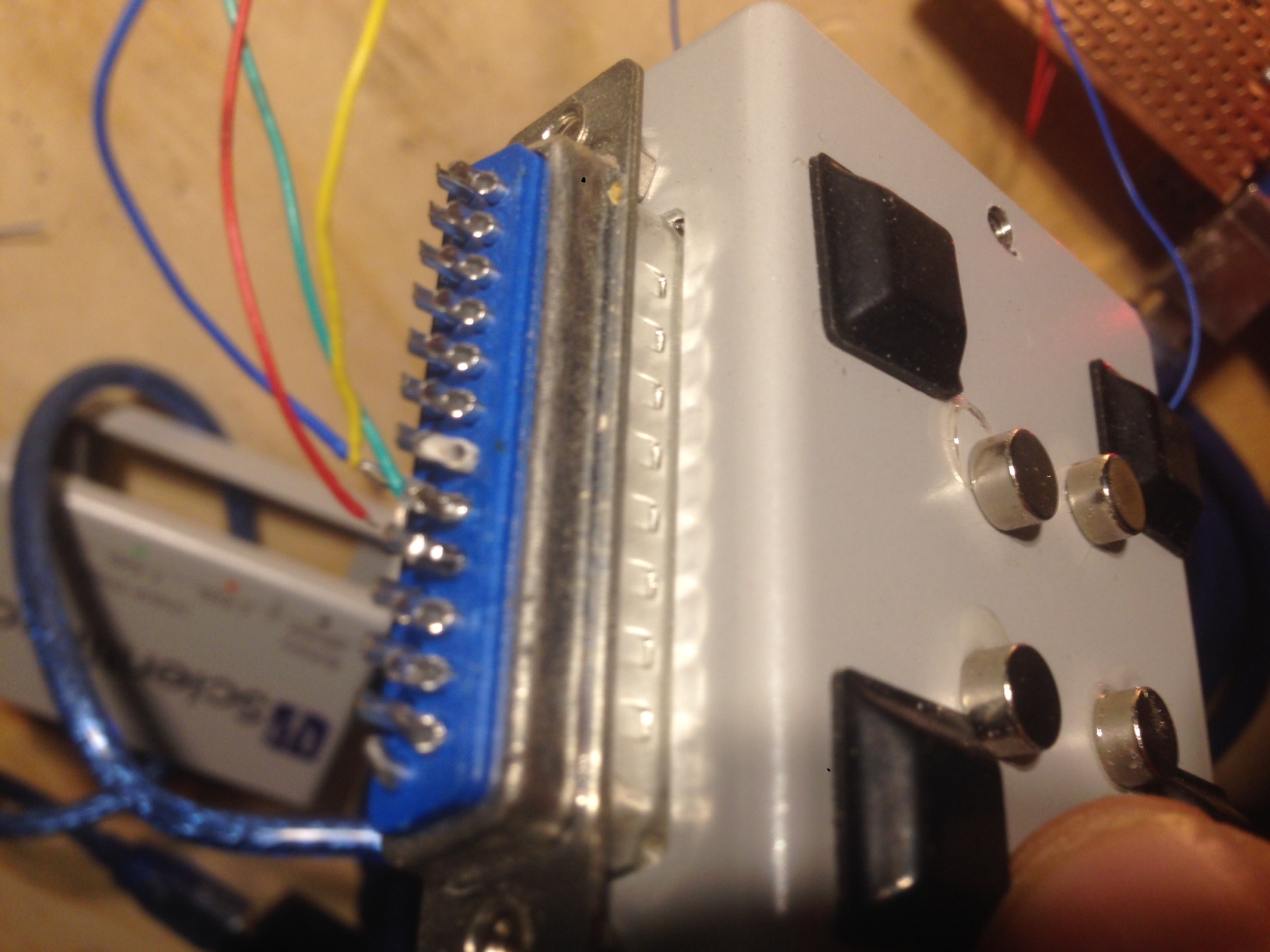
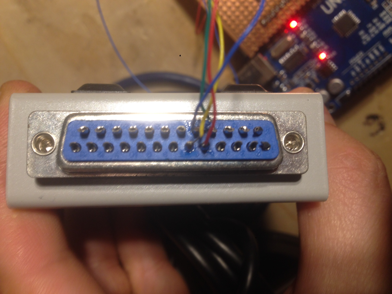
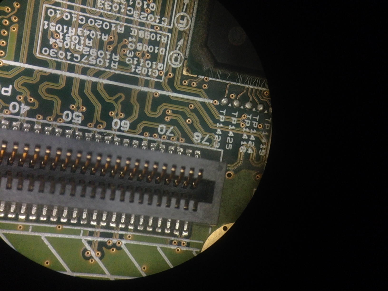
I also a traced out the header (see below), the +/- ~20v signals appear to match the mirror bias/reset signals, but I wasn’t able to see anything on what looked like differential pairs going into the DMD. And without the datasheet I’m not quite sure what the signals should look like.
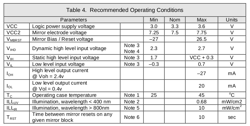
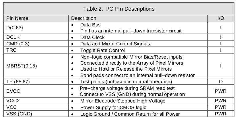
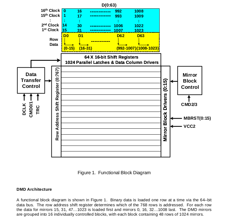
There is 9 page datasheet for the DMD device itself though the part number doesn’t match completely. In typical vendor style they’ve also masked out all the pinout information (available under NDA I’d guess). A few screen grabs below…
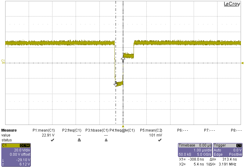
Pin 7 etc. Mirror reset/bias
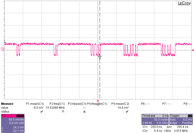
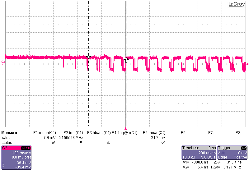
Example of what I assume is LVDS trace:
Length matched differential traces?:
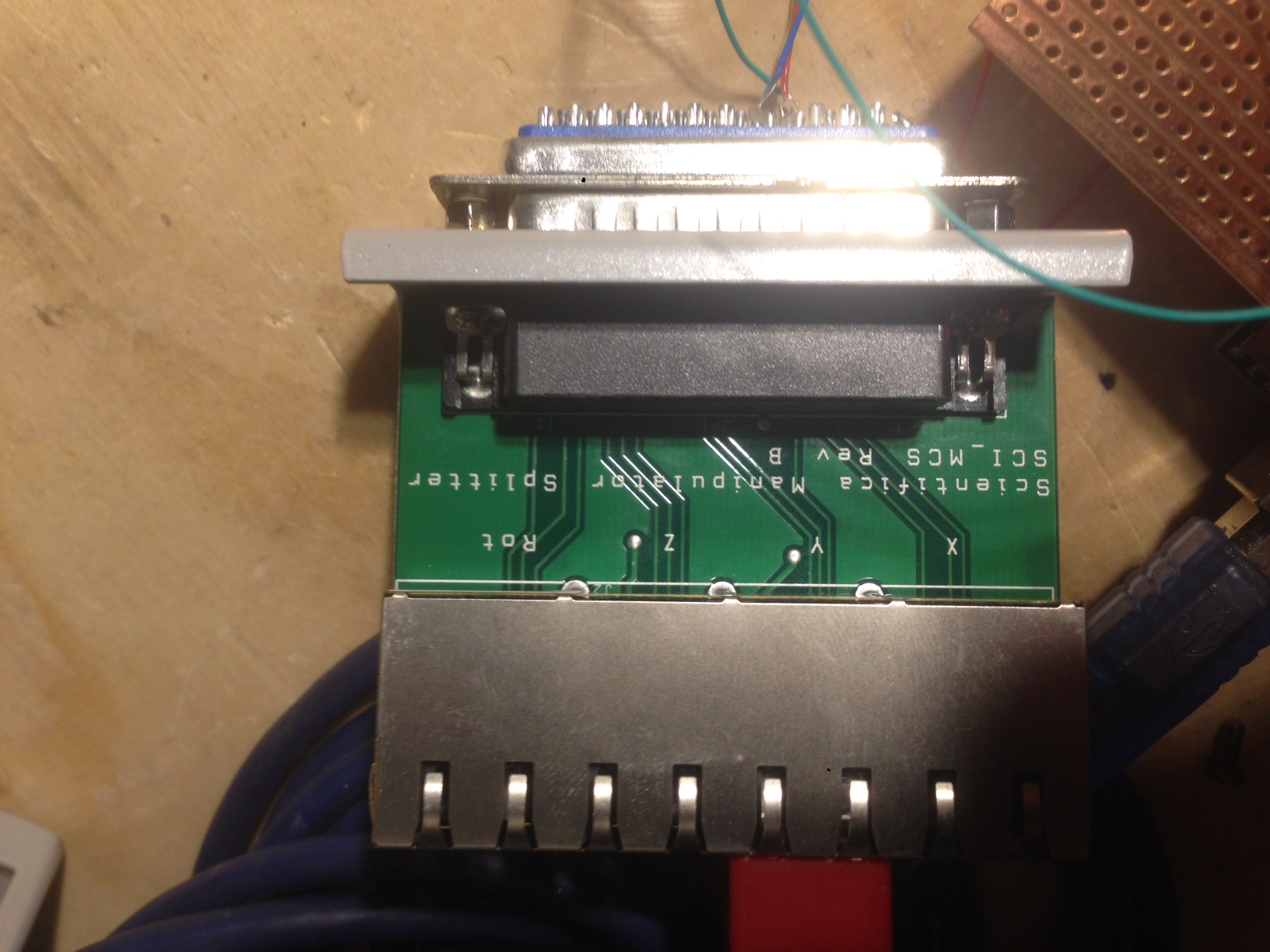
Tracing out the header:
1: 3.2v
2:
3: 3.2V
4:
5: 0V
6:
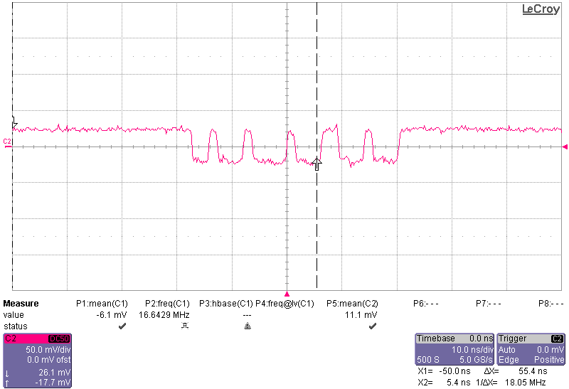
7: +20 TO -20 300NS FIRST NEG THEN GND THEN POS. BASELINE IN +20v
8:
9: as 7
10: as 7
11: as 7
12: 7
13: as 7
14: as 7
15: as 7
16: 7
17: as 7
18: 7
19: as 7
20:7
21: as 7
22:7
23: 0
24: 0
25: 0
26: 3
27: 2.3v
29: 0
30: 0
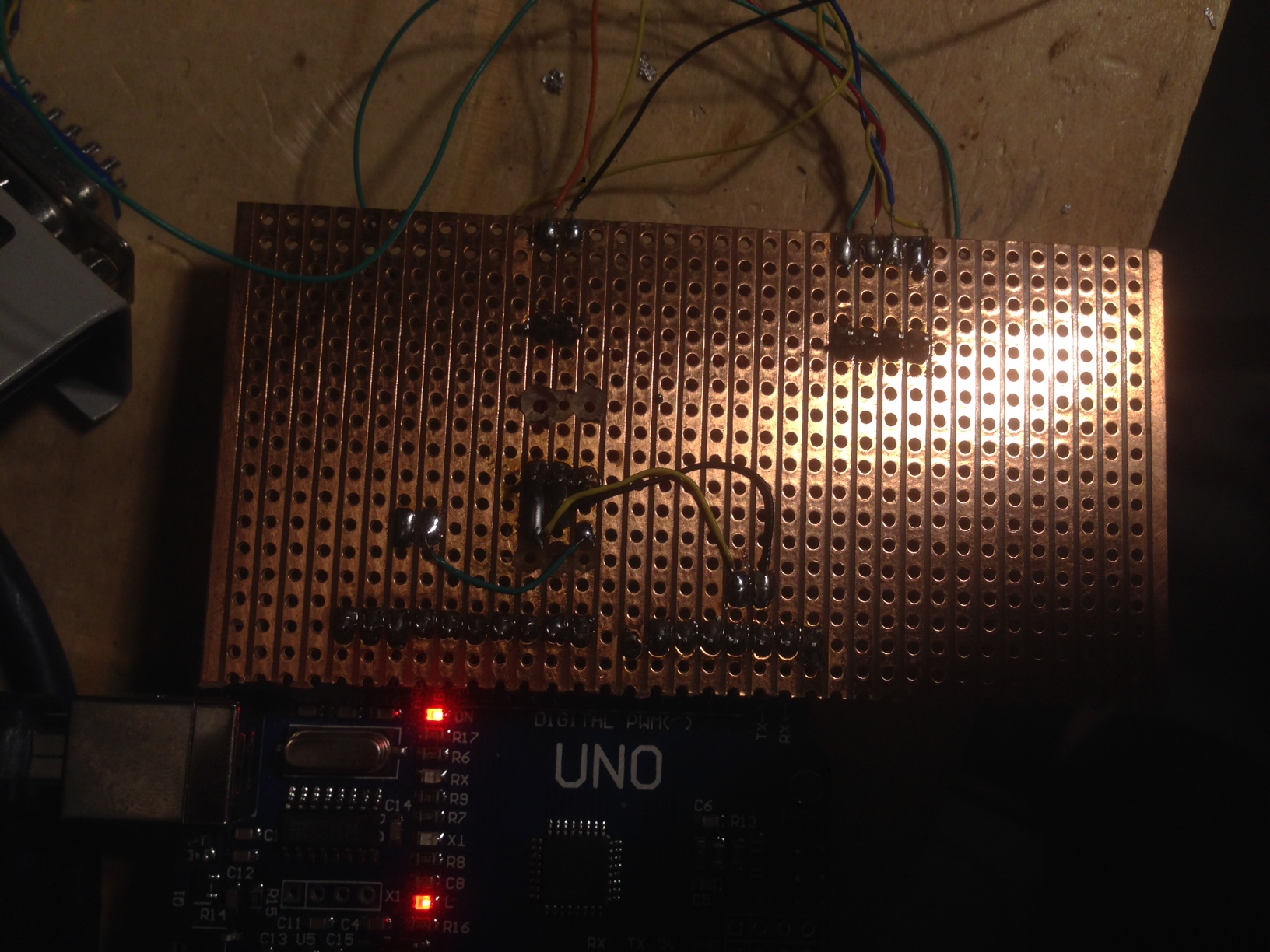
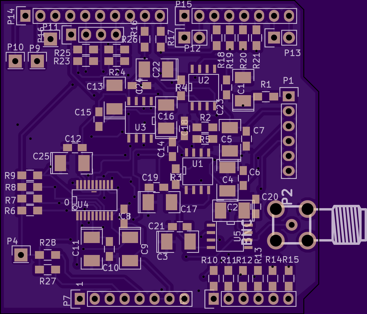
There were a few problems with the previous revision. Basically a screw up with one of the tracks. Only one bodge wire required on the build. Next version is out to fab, but this revision should be good enough for my purposes.
My name is Nava Whiteford. I’ve worked for a few sequencing companies. I have equity in a few sequencing companies based on my previous employment (I try to be unbiased in my posts). You can contact me at: [email protected]