Philips hair clipper PCB
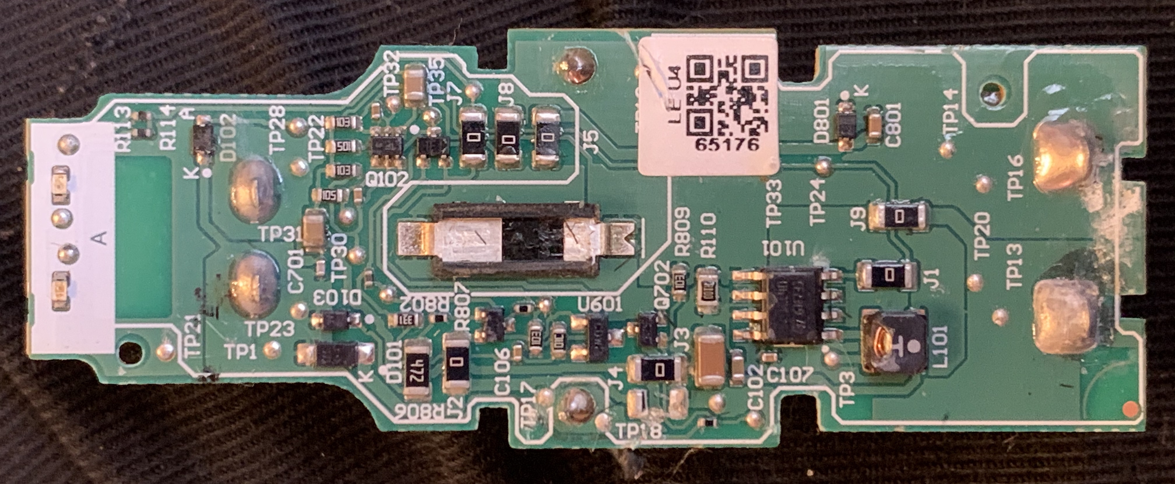
The above images show the control PCB from a Philips hair clipper. The board takes a 15v input and controls what looks like a 6v brushed motor.
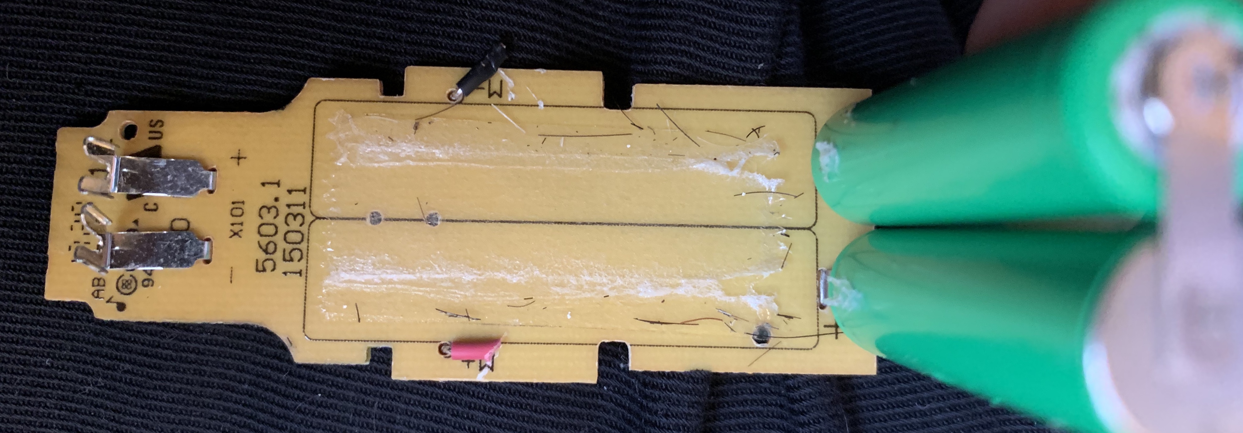
The PCB has two Suppo 750mAh AAA NiMH cells attached to it. My guess is that U101 is a boost converter for the ~2.4v from the battery. This seems likely given that an inductor sits next to it and given the designation of the inductor (L101).
I also find it interesting that they’ve gone with a single sided PCB and used 7 zero ohm SMD resistors to bridge traces. I see single sided PCBs in cheap toys a lot. But this board surprisingly has mask and silk. If the single sided board is motivated by cost, then I’m surprised that there is significant cost benefit…
I attached a 5v supply to the motor (you can see the red and black wire stubs where the motor attached in the images above). With a 5v supply the motor works as expected.
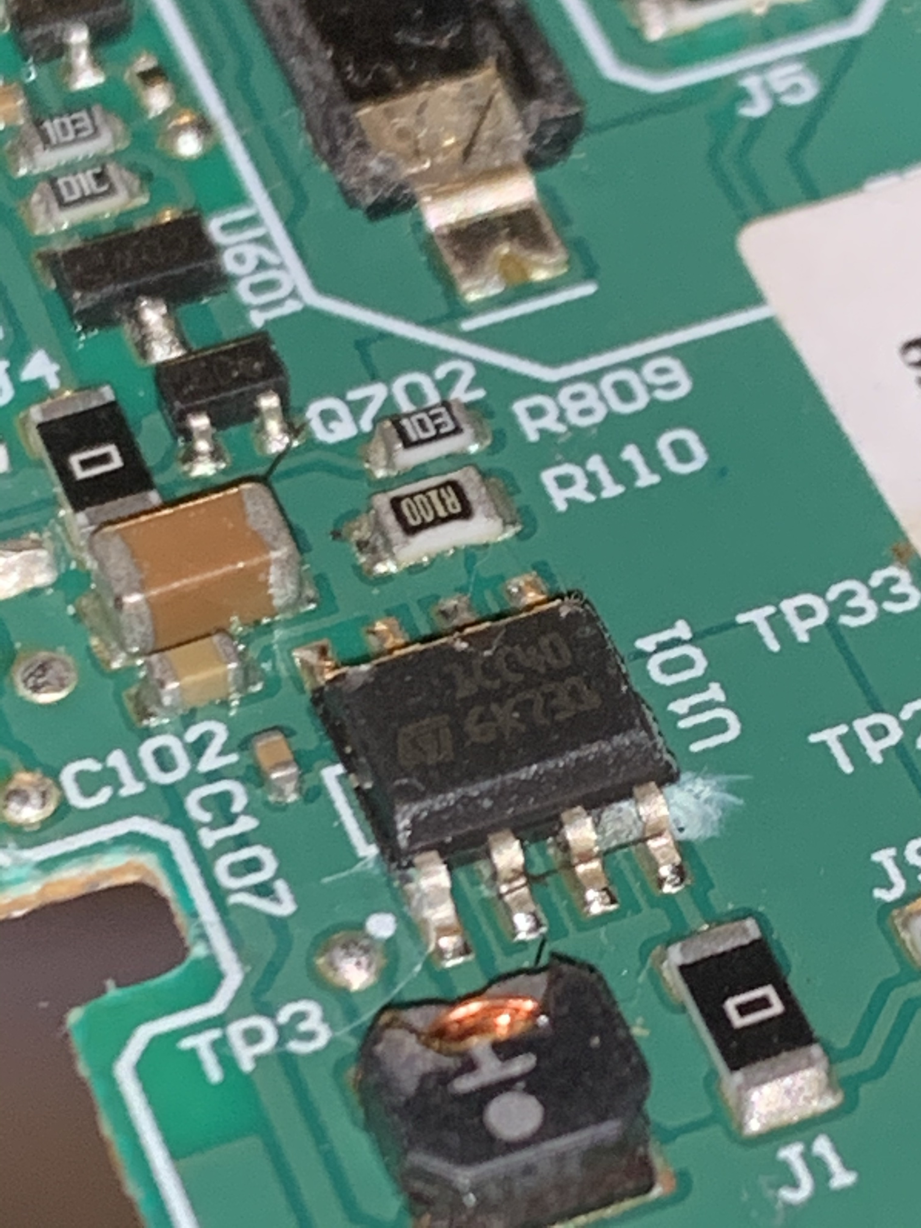
Close up of the IC. 1CC40 6K731? Looks like this part: https://www.st.com/content/ccc/resource/technical/document/datasheet/group3/71/e8/26/3c/c8/cc/46/e6/CD00292360/files/CD00292360.pdf/jcr:content/translations/en.CD00292360.pdf