ESP8266 Notes
Today we’ve been playing around with some ESP8266 boards. This IC uses a lx106 32bit core, running at 80MHz, and have ~80K of RAM and use serial EEPROM which is generally around 512Kb. They also have an integrated Wifi RF frontend.
We used the toolchain available here to get the boards programmed.
The boards can be programmed using 3.3V RS232 signals, so a basic FTDI USB adapter works well.
When programming pins 3 and 4 need to held high. Pin 5 should be held low. I built a board to tie these pins to the correct values, as a programming interface between the FTDI board and the ESP8266 as follows:
Prog board 1:

Prog board 2:

Prog board 3:

Prog board 4:

While you can use this board of programming, the pins should not be pulled up/down on board. The ESP8266 can also require upto 1A when running with the Wifi up. On my tests I also tied pin 4 and 6 high in the running configuration (however I’m not sure if this is actually required) anyway, I built up these boards for the running config:
Power board front:

Power board back:

I flashed the device with the blinky demo from the Toolchain examples, however the LED on our boards is not connected to GPIO2 (which the demo uses). However the output was easily visible on a scope:
Scope output:

Resources
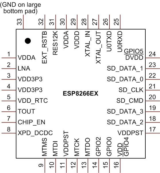
Pinout:
Wiki page with a bunch of useful info: here
Core Datasheet with instruction set etc: here
Core Marketing summary: here
IC Datasheet: here
Random notes:
Also need:
apt-get install gperf
apt-get install bison
Update path:
PATH=$PATH:/opt/Espressif/crosstool-NG/builds/xtensa-lx106-elf/bin
PATH=$PWD/builds/xtensa-lx106-elf/bin:$PATH