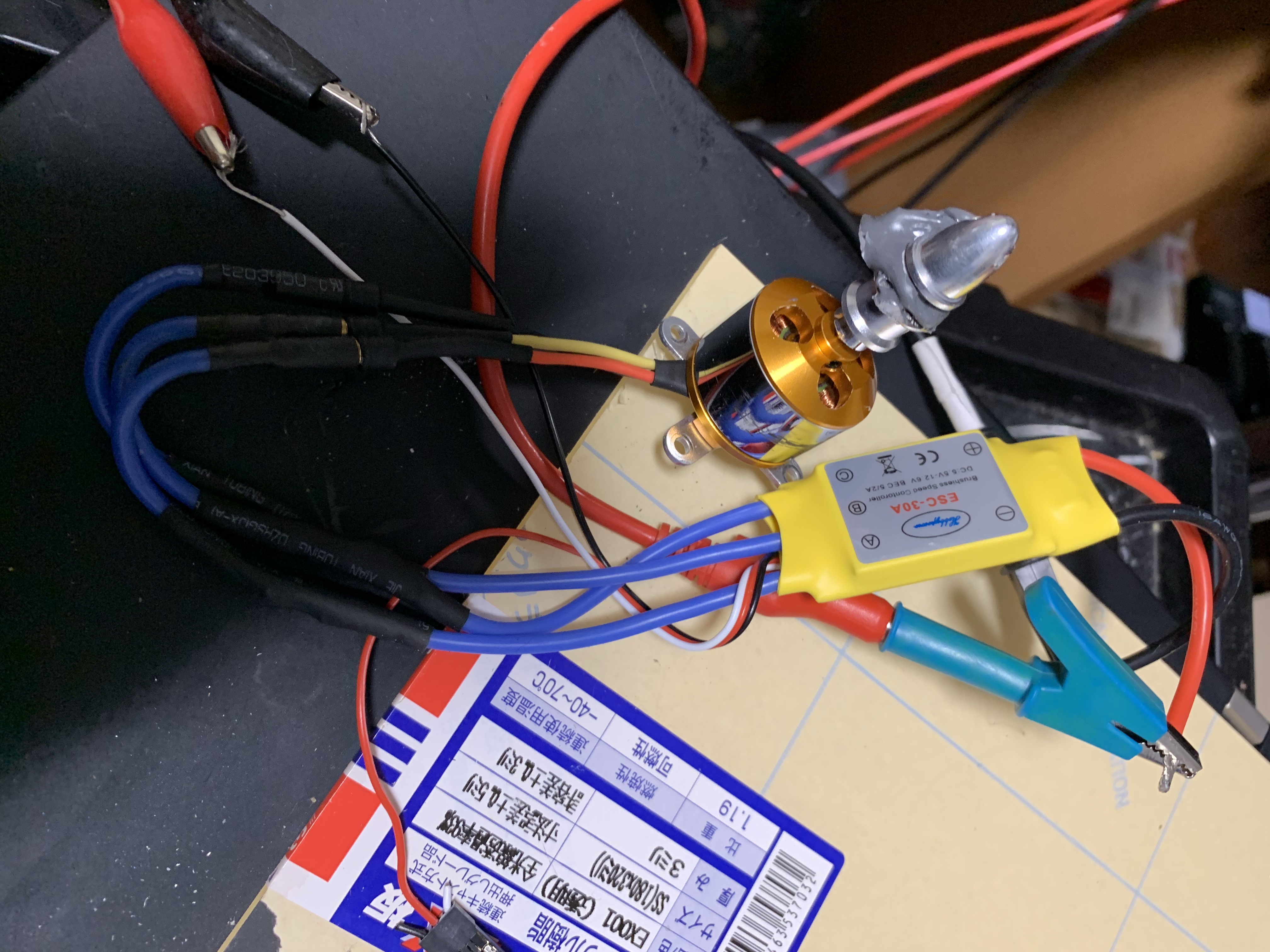
ESC-30A Brushless DC motor driver Notes
I have a few of these cheap brushless dc motor drivers. The contain a small MCU and what appear to be half bridges (and I assume sense back EMF).
I generally want to drive these from a function generator for quick experiments. The documentation isn’t written with this in mind, and it always takes me a little bit of fiddling. So here are my notes for next time.
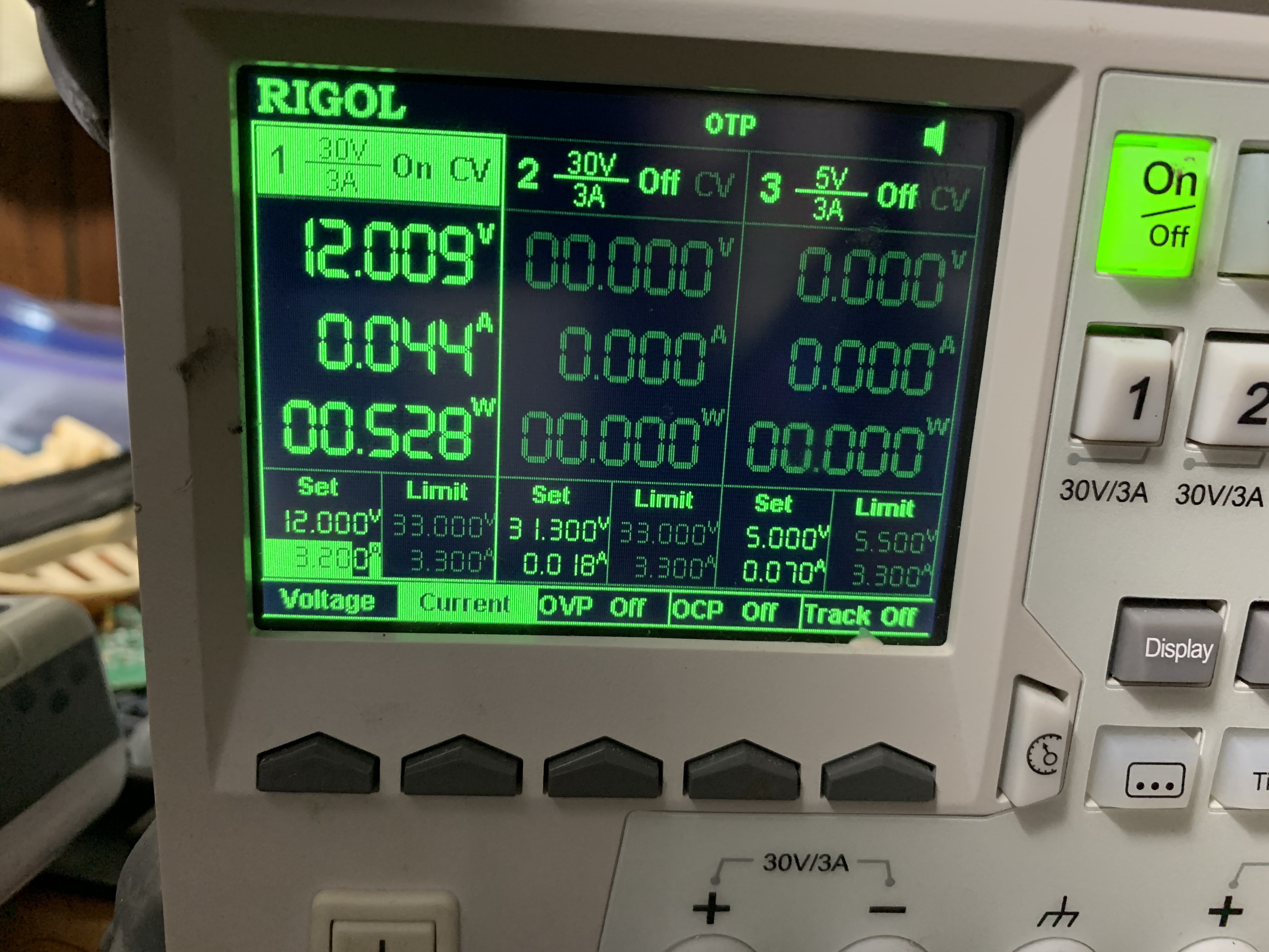
The driver can be powered by 12V DC. Looking at the transistors, it seemed like anything over about 20V could potentially fry the driver.
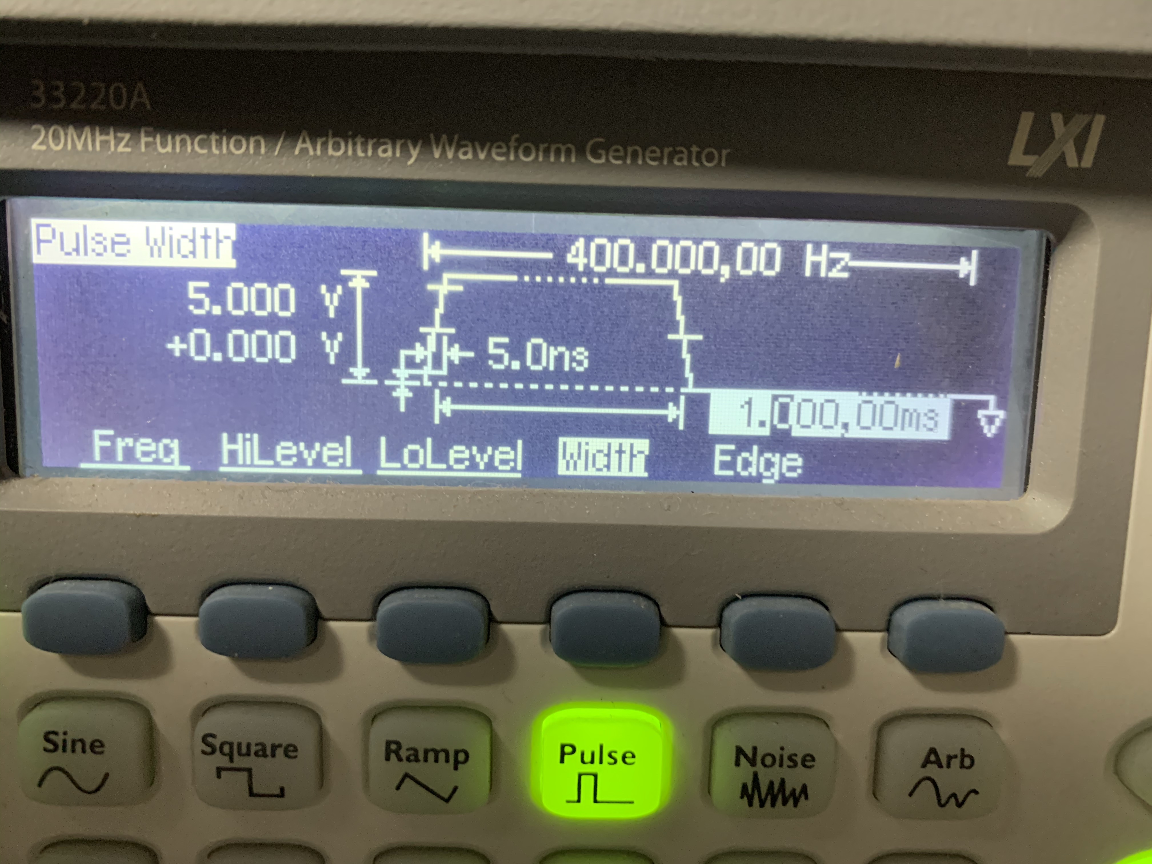
To initialize the driver you need to apply the “low throttle” signal. This is a short pulse at 400Hz. I use a 1ms pulse, which seems to be fine.
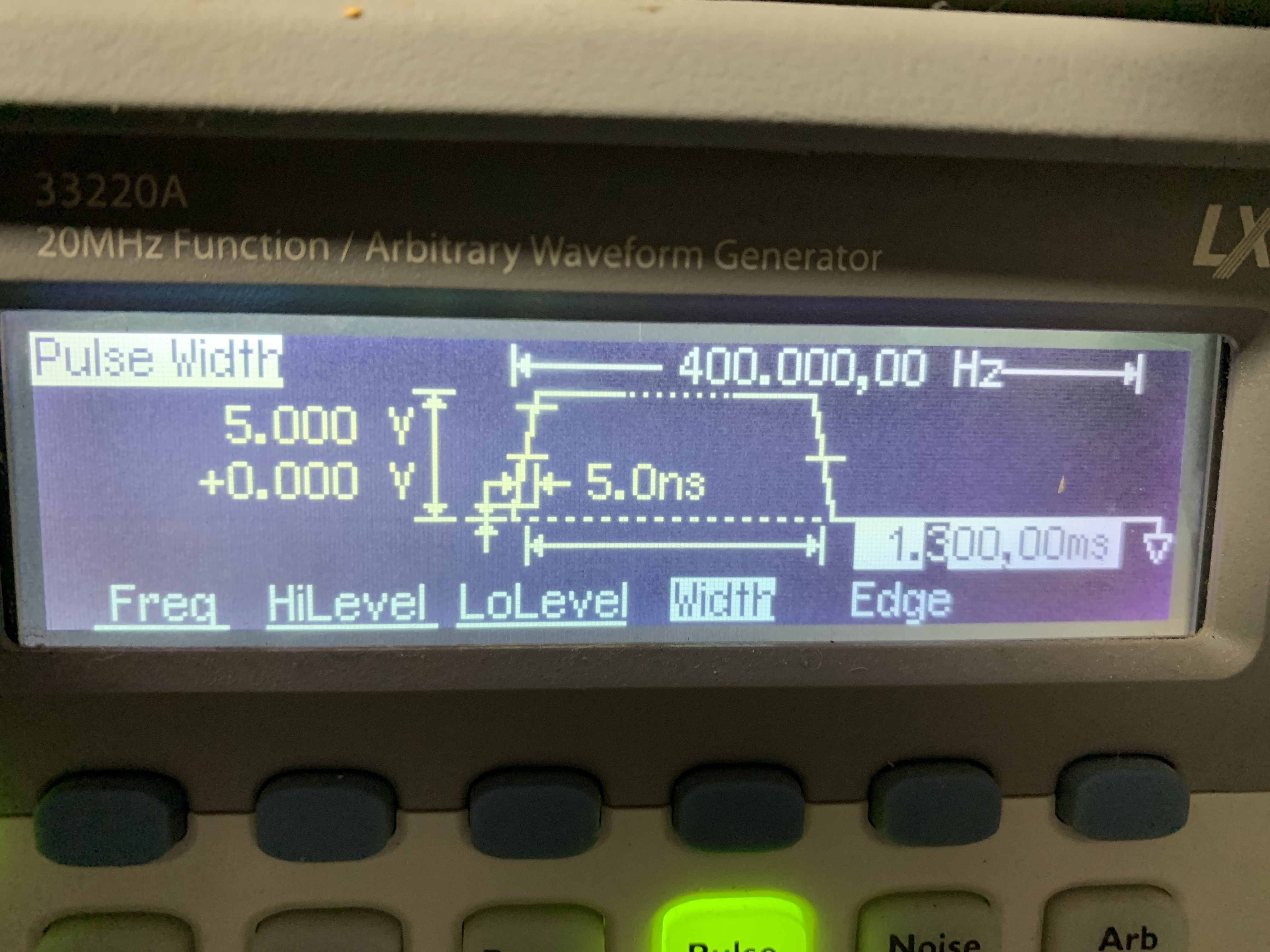
To get the motor running increase the pulse width. Maximum is 2ms. Applying a 2ms pulse when powering up the driver will not work.
The control interface generally has 3 pins. Red, Black and White. White is the control signal. Black is ground. The driver has an onboard regulator to power the MCU, so you don’t need to supply anything to the red pin (which I assume can also power the regulator, and is potentially useful for reprogramming?).
This documentation matches the driver I have:
http://www.sarkanyellato.hu/wp-content/uploads/2011/10/RC-Timer-10.18.30.40A-ESC-Instruction.pdf
Reference images below: