Fiddling with a cheap 5 port dumb switch to add VLANs/port mirroring
I’ve been hacking away at this cheap Shenzhen switch. If you’re interested in hacking on it, you can buy the exact model on my shop here. This also helps fund these hacks.
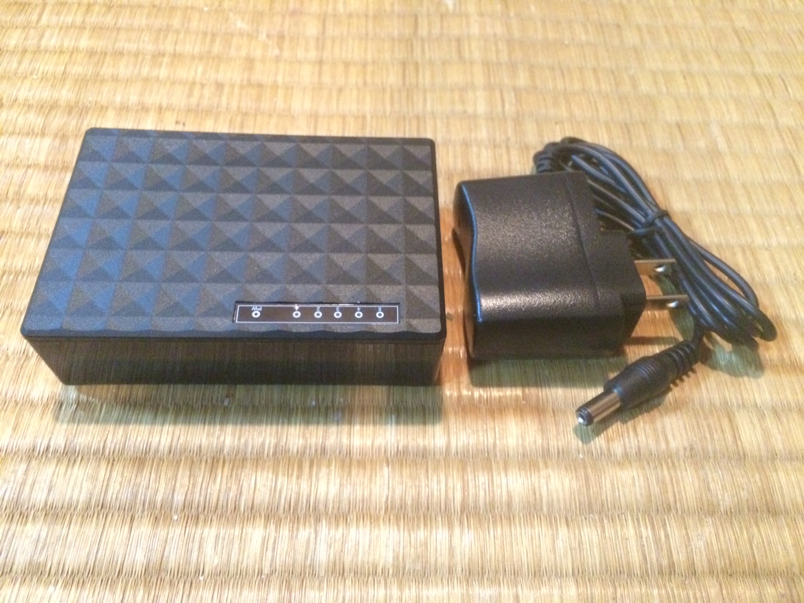
I picked up this switch on eBay. The seller described it as a gigabit switch, however when I opened it up it contained a IP178GH which is a 10/100 switch on a chip. Some googling locates a pretty decent datasheet for this IC (local copy: IP178G_IC).
While it’s only a 10/100 switch the datasheet is pretty interesting and shows it contains a full management interface. While it contains VLAN and other functionality, I was particularly interested in the port mirroring, which comes in handy when debugging network traffic (port mirroring forwards all TX and RX traffic to another port on the switch where you can monitor it with a packet sniffer like wireshark).
The datasheet describes how the management interface can be used. There are 2 modes of operation. One is that configuration can be loaded from SPI flash. The board contains an unpopulated footprint for the SPI flash, and at some point I plan to try this out.
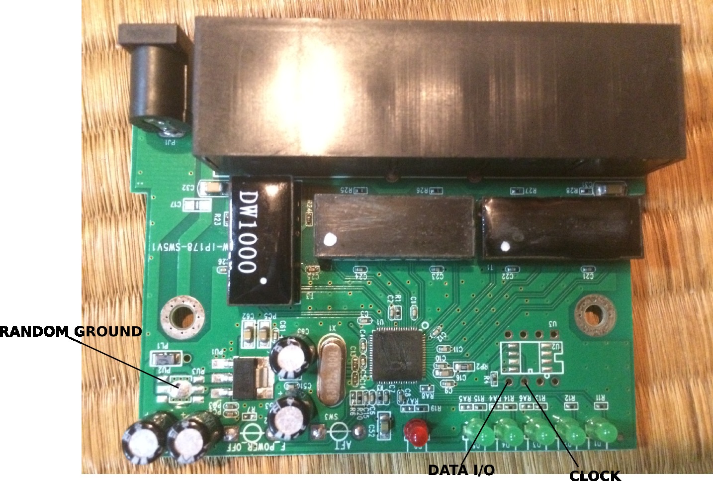
However there’s a second “Serial Management Interface” which allows the switch configuration to be changed on the fly from an external microcontroller. Conveniently the 2 pins required are broken out on the board:
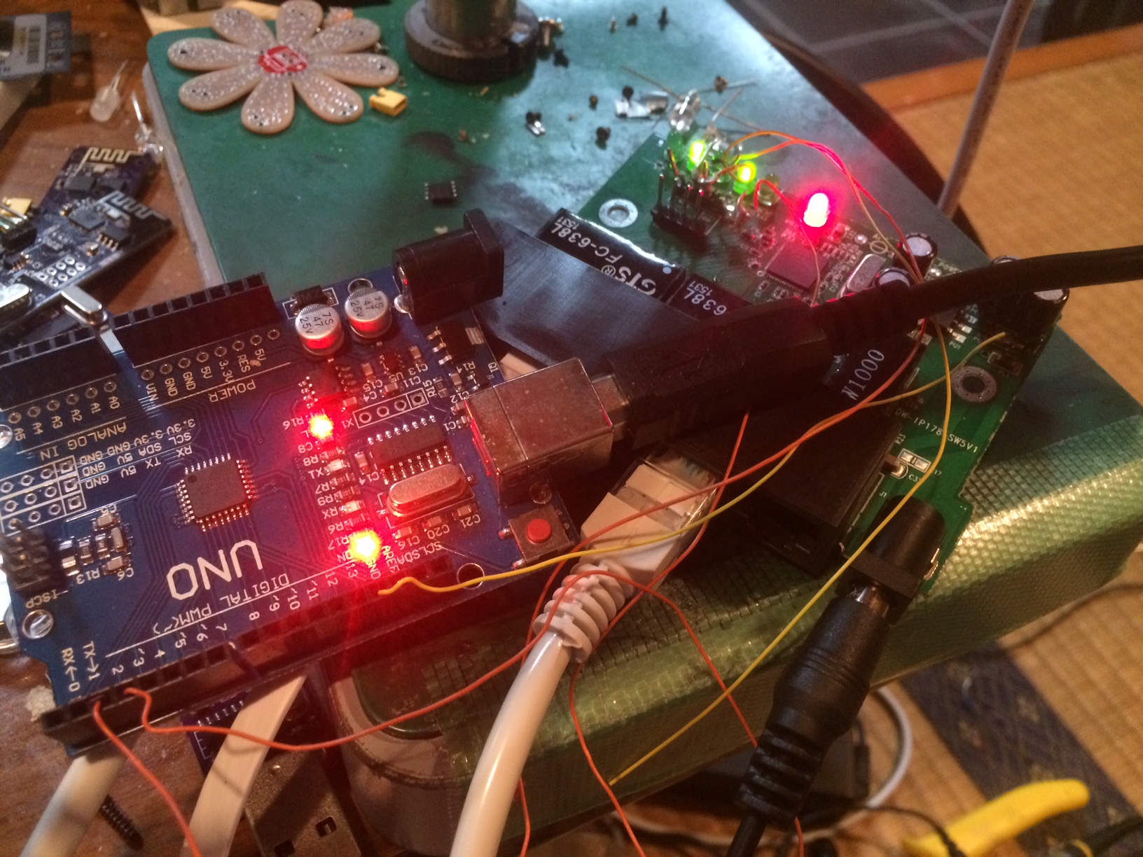
It seems they are also 5v tolerant, which means we can just throw an Arduino at them and bit bang an interface. Here’s my rather messy setup:
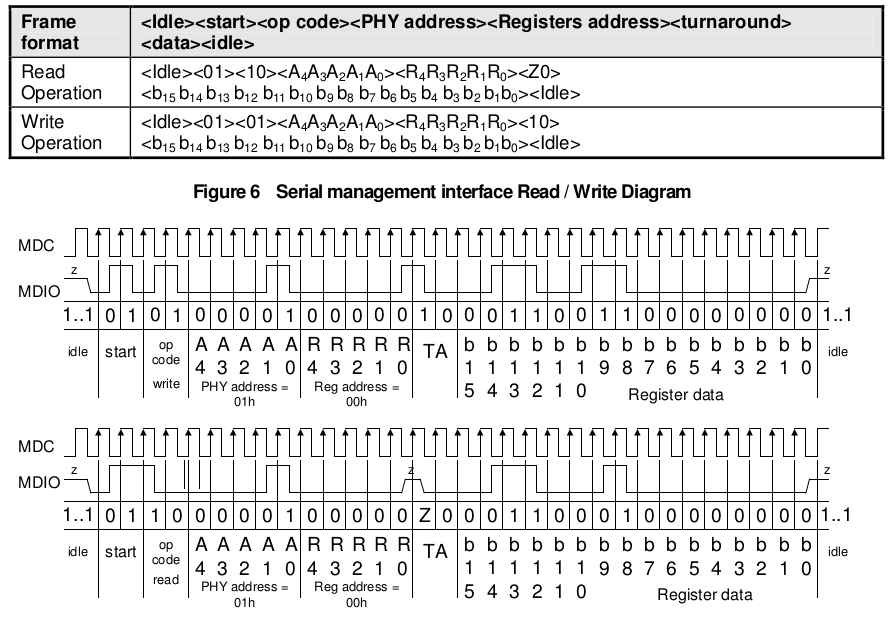
The interface is a pretty simple half-duplex serial interface. There’s a timing diagram in the datasheet, though I didn’t see any clear information about clock speed. I used a clock rate of about 1KHz which seemed to work (I honest didn’t read the datasheet in detail, full details might be there somewhere).
It also contains a full description of the register configuration. As I was particularly interesting in the mirroring config, and the example below programs these registers, here it is:
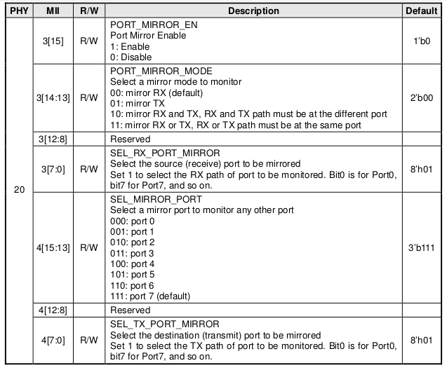
With this in hand I was able to program phy 20 registers 3 and 4 to enable port mirroring from port 0 to port 1 and confirm that this worked correctly. The hacky Arduino code I wrote the included below, you should attach the clock to pin 2, data to pin 3 and make sure the ground is correctly connected.
The code is a mess, but it might prove useful if you’re trying to replicate this work.
int clock_pin = 2;
int data_pin  = 3;

int width=100;

void setup() {
  pinMode(clock_pin, OUTPUT); // CLOCK
  pinMode( data_pin, OUTPUT); // DATA
}

int recv_one_bit() {
  //Serial.print("1r");
  int data=0;
  digitalWrite(clock_pin,0);
  delayMicroseconds(width);
  digitalWrite(clock_pin,1);
  delayMicroseconds(width/2);
  data = digitalRead(data_pin);
  delayMicroseconds(width/2);
  digitalWrite(clock_pin,0);
  return data;
}

void send_data_bit(int data) {
  //Serial.print("1s");
  digitalWrite(clock_pin,0);
  delayMicroseconds(width/2);
  digitalWrite(data_pin,data);
  delayMicroseconds(width/2);
  digitalWrite(clock_pin,1);
  delayMicroseconds(width);
  digitalWrite(clock_pin,0);
}

void outhigh() {
  pinMode(data_pin,OUTPUT);
  digitalWrite(data_pin,1);
  digitalWrite(clock_pin,0);
}

void send_data(uint32_t data,int len) {

  for(int32_t n=len-1;n>=0;n--) {
  //for(int32_t n=0;n<len;n) {
    if(data & ((uint32_t)1 << n)) {
      send_data_bit(1);
    } else {
      send_data_bit(0);
    }
  }
}

uint32_t recv_data(int len) {

  //Serial.print("len: ");
  //Serial.println(len,DEC);
  uint32_t datain = 0;
  for(int32_t n=(len-1);n>=0;n--) {
    //Serial.println(n);
    int d = recv_one_bit();
    if(d != 0) {
      datain = datain | (uint32_t)((uint32_t)1 << n);
     // Serial.println("h");
     // Serial.println(((uint32_t)1<<n),HEX);
      //Serial.println(datain,HEX);
    }
  }
  return datain;
}

uint32_t read_op(int phy,int reg) {

  pinMode(data_pin,OUTPUT);
  send_data_bit(1);

  send_data_bit(0);
  send_data_bit(1);
  send_data_bit(1);
  send_data_bit(0);

  //send_data(1,2); // start bits
  //send_data(2,2); // read operation
  send_data(phy,5);
  send_data(reg,5);

  pinMode(data_pin,INPUT);//INPUT_PULLUP

  uint32_t in;
  int inA = recv_one_bit(); // turn around
  //int inB = recv_one_bit(); // this should be required as per spec, but a bit gets missed if I use it.

  in = recv_data(16);

  Serial.println("ta bits:");
  Serial.println(inA);
  //Serial.println(inB);

  outhigh();
  //send_data_bit(1);

  return in;
}


void write_op(int phy,int reg,uint32_t data) {

  pinMode(data_pin,OUTPUT);
  send_data_bit(1);

  send_data_bit(0);
  send_data_bit(1);
  send_data_bit(0);
  send_data_bit(1);

  send_data(phy,5);
  send_data(reg,5);

  send_data_bit(1);
  send_data_bit(0);
//  send_data(2,2); // Turnaround

  send_data(data,16);
}


void loop()
{
  Serial.begin(115200);

  outhigh();
  delay(1000); // one second

  uint32_t data = read_op(20,3);
  Serial.print("Old Read3: ");
  Serial.println(data,HEX);

  data = read_op(20,4);
  Serial.print("Old Read4: ");
  Serial.println(data,HEX);

  //Port mirroring config sits in phy 20, regs 3 and 4.
  //The bit pattern is shown below. See the datasheet for further details.
  //15.......................0
  //   enable, mode, res, mirrored port rx
  //3: 1,   11,00000,00000001
  //
  //   monitoring port, res, mirrored port tx
  //4: 001 ,00000,00000001

  uint32_t reg3 = 0xE001;
  uint32_t reg4 = 0x2001;

  write_op(20,3,reg3);
  write_op(20,4,reg4);
  delay(1000); // one second

  data = read_op(20,1);
  Serial.print("1Read1: ");
  Serial.println(data,HEX);

  data = read_op(20,2);
  Serial.print("1Read2: ");
  Serial.println(data,HEX);

  data = read_op(20,3);
  Serial.print("2Read3: ");
  Serial.println(data,HEX);

  data = read_op(20,4);
  Serial.print("2Read4: ");
  Serial.println(data,HEX);
}
Cool. All that work is still going to be a damn sight easier than having to install Adobe AIR and some awful Netgear software on a Windows PC just to set up a VLAN… ugh!
Switch in question for those interested: https://www.amazon.co.uk/gp/product/B004G9IXSC/ref=oh_aui_search_detailpage?ie=UTF8&psc=1
Avoid.