Beckman DU530 Photospectrometer notes
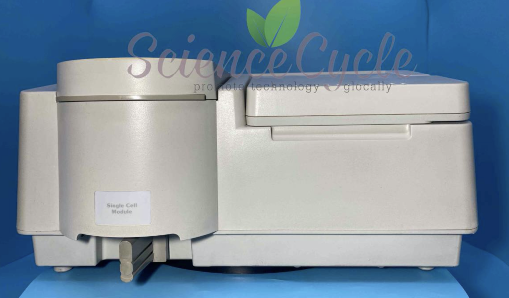
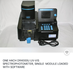
This post contains various notes on the DU530 Photospectrometer, it’s incomplete as my unit is not functioning, but never the less, my notes are here for future reference and in case they are of some use. As far as I can tell the DU 500 series is a rebadged Hach DR4000U, many of the PCBs are marked “Hach” which further supports this. And the Hach instrument looks very similar, though in stylish black:
This is helpful, as while I’ve not been able to find a 500 Series manual online, there however a manual for the DR4000:
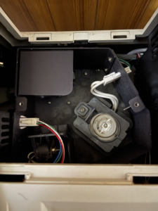
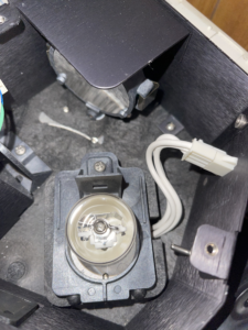
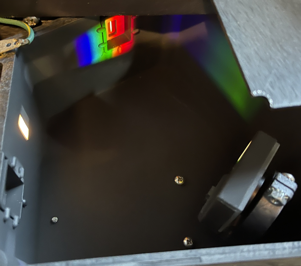
The DU 530 contains two light sources a small visible light lamp and a Deuterium UV lamp. This is model L2D2 and uses a 3 pin connector. The instrument appears to supply this with 12V. On my unit the Deuterium lamp appears to have failed. The unit will Pass all tests except the wavelength calibration. The unit will pass all other tests even without the lamp connected. The failure code on my unit is “24: Monochromator”.
As far as I can tell, the power on calibration doesn’t appear to try and power up the Deuterium lamp, which seems odd. It could be briefly powering the bulb and detecting a short/no current draw perhaps. It does seem to ramp up to ~600mV a few times so prehaps it’s checking the lamp resistance first. However when using the diagnostic mode (below) to fire up the lamp, it just goes straight to 12v…
It’s possible to enter a diagnostic mode when tests fail. You will be prompted for a “Service code”, after much experimentation this appears to be 3210, at least this is the case on my unit. This will let you enter a “System Check” menu. In this menu you can select various tests, for example to test motors, the keypad and display. By pressing the “SETUP” key on the keypad you can enter another menu. In this menu you can fire up the Deuterium lamp.
Overall the instrument hardware seems pretty serviceable. Only three Phillips screws hold the cover on, the keypad and some electronics are attached to the case, but cables are long enough to allow operation with the cover removed and placed to one side.
The instrument will pass all tests up to Lamp Alignment without any lamps installed. Lamp alignment will pass using only the visible lamp (and I suspect if there’s no issue all tests will pass using the visible lamp only). The instrument doesn’t seem to have anything to detect if the lamps are disconnected (other than the fact that wavelength/alignment tests will fail).
Unfortunately, I’ve not been able to find a user or service manual for the instrument. Though manuals for similar instruments are below (600 and 700 series).
This post has some information on error code 24: https://www.labwrench.com/thread/160951/refused-calibration
“Typically, an error code 24 required a reinitialization of the spectrophotometer using a special software program and cell holder module. This can only be done by a service engineer that actually has the software and cell holder. Before going that route you might check the condition of your visible lamp and how clean your optics are. If your visible lamp’s envelope is darkened and or bubbled, replace it and try again.”
An open source program to read serial output is available here: https://github.com/Schallaven/Beckman-DU-520-reader (I have not tested this). With the tests failing, I’ve not been able to see any serial output from the unit during boot. I wonder if there’s some way to enable a serial debug interface…
Datasheet for UV lamp used in this instrument:
DU 700 Series Manual: https://physiology.case.edu/media/eq_manuals/eq_manual_beckman_du700_.pdf
DU 600 Serial Manual: https://www.dbi.udel.edu/wp-content/uploads/2017/07/beckman-du-600-series-.pdf
ADC Datasheet: https://www.mouser.com/datasheet/2/76/cirrs01119_1-2263004.pdf
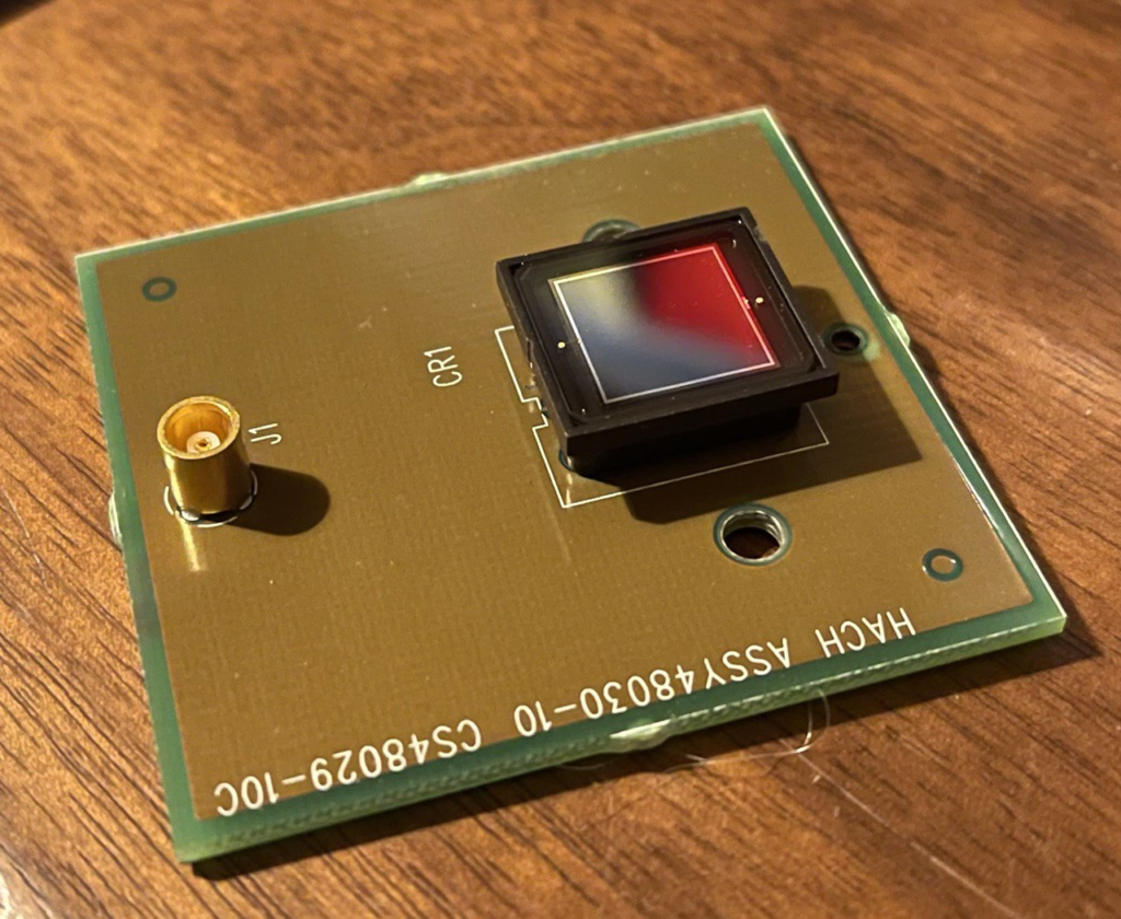
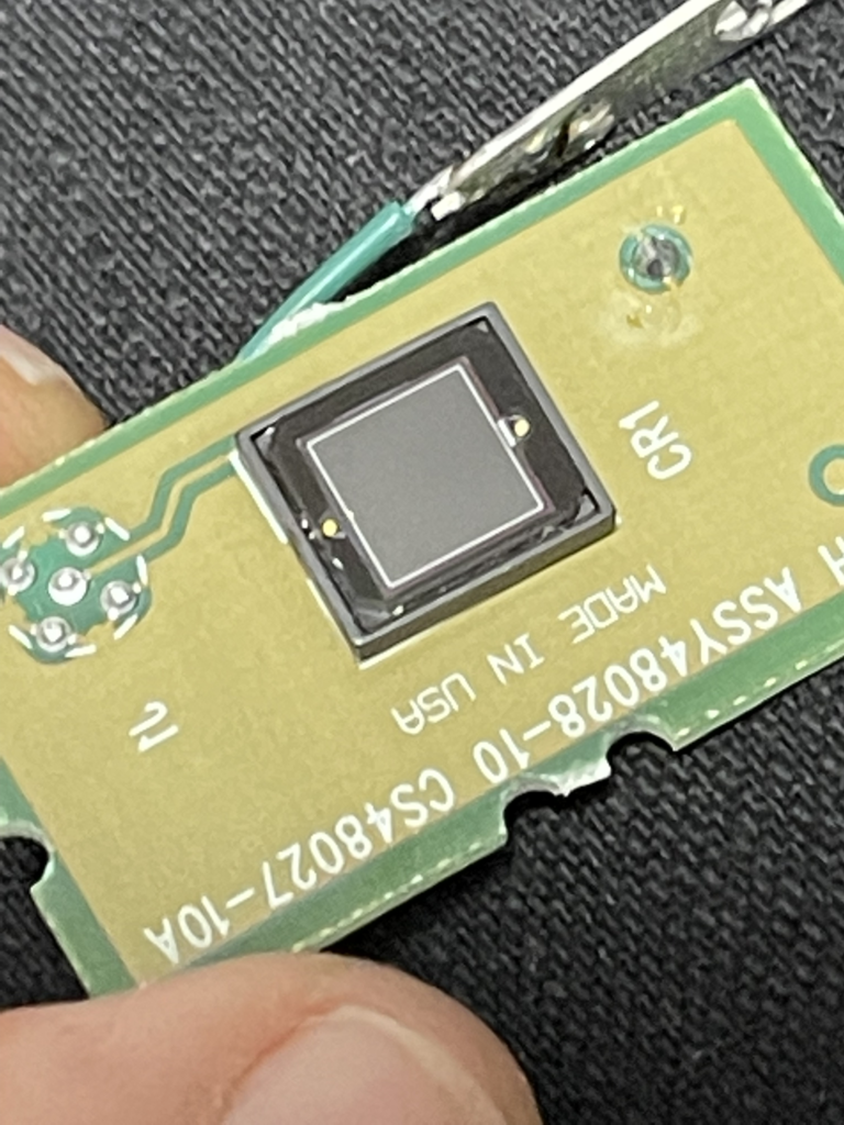
Photodiode (output side): Best I can tell is this is a S227-1010BQ, which specs sensitivity down to 190nm. Datasheet here: https://www.hamamatsu.com/resources/pdf/ssd/s1227_series_kspd1036e.pdf
Further notes on the photodiode amplifier circuit are here.
Tested the photodiodes with a transimpedance amplifier, un-biased:
Under ambient light the small (input side) photodiode outputs about 0uA and >450uA under illumination.
Under ambient light the large (output side) photodiode outputs about 20uA and > 450uA under illumination.
Steppers used on the lamp alignment mirror and grating are Oriental Motor, Vexta PX243M-03AA-C6 and PX243M-03AA-C9, 2-phase 0.9deg/step. DC 12V 0.3A. Datasheet: https://www.orientalmotor.com/products/pdfs/opmanuals/HM-601-17JECK.pdf
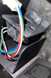
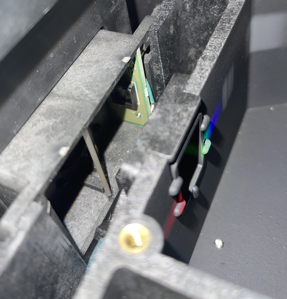
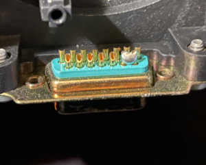
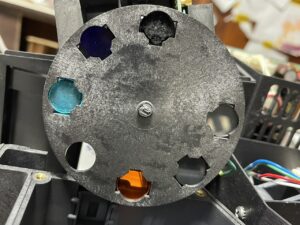
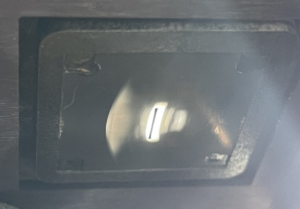
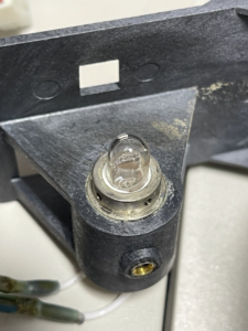
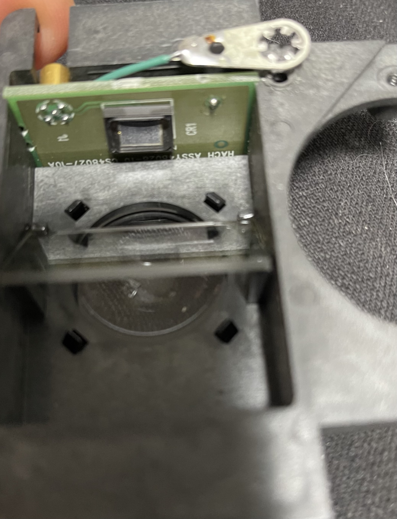
Pics of various parts of the instrument below: