Archive for the ‘Uncategorized’ Category.

Archer A10 V2.0 JP OpenWRT

This is an update to the bundle posted yesterday.

The install bundle requires UART access which is pretty easy. RX/TX are the pins nearest the side of the case of the left.

Codex built a two stage installer. The first loads a RAM image over tftp. So you need to enter uboot (press t while booting 115200 8N1 works). Then start up a tftp server.

Here’s the overly verbose approach Codex made… files below.

Installation command sheet

Use the binary release bundle, Linux, 3.3 V UART and isolated Ethernet.
Connect Ethernet to WAN initially. Connect UART GND/RX/TX with TX/RX crossed; do not connect the adapter’s power pin. Substitute enp3s0 and /dev/ttyUSB0.
Read INSTALL_FROM_STOCK.md for expected model/partition sizes and failure handling.
The exact new installer and pristine-overlay installation have not been hardware-tested.

1. HOST — prepare Ethernet, UART and servers

Run UART, TFTP and HTTP servers in separate terminals; leave servers running.

tar -xzf archer-a10-v2-port-with-images.tar.gz
cd archer-a10-v2-port
sha256sum -c SHA256SUMS
sudo apt install tftpd-hpa picocom python3 openssh-client
sudo systemctl stop tftpd-hpa
WIRED_INTERFACE=enp3s0
sudo ip link set "$WIRED_INTERFACE" up
sudo ip addr replace 10.42.0.1/24 dev "$WIRED_INTERFACE"
picocom -b 115200 /dev/ttyUSB0
sudo in.tftpd --listen --foreground --address 10.42.0.1:69 \
  --secure "$PWD/install/tftp"
python3 -m http.server 8000 --bind 10.42.0.1 --directory install/payload

2. UART/U-BOOT — load OpenWrt into RAM

Select boot menu 4. Require image_boot=0, image_copy=1. Wait for complete TFTP transfer before bootm. Never saveenv.

printenv image_boot image_copy
setenv autostart no
setenv autoscript no
setenv ipaddr 10.42.0.185
setenv serverip 10.42.0.1
tftpboot 0x84000000 archer-a10-v2-stock-installer-ram.bin
bootm 0x84000000

3. ROUTER — establish Ethernet and verify the installer

ubus call system board
cat /proc/mtd
ip link show
ip addr add 10.42.0.185/24 dev br-lan
ping -c 3 10.42.0.1

The model must be TP-Link Archer A10 v2 (OS0-only installer RAM environment) and rootfs must be initramfs. Verify the partition map against INSTALL_FROM_STOCK.md.

4. HOST — save this router’s own backups before writing

The last block runs on ROUTER. Compare all seven backup hashes and sizes before proceeding.

mkdir -m 700 backups
for idx in 0 1 2 3 4 5 6; do
  ssh -o UserKnownHostsFile=./installer-known-hosts \
    -o StrictHostKeyChecking=accept-new [email protected] \
    "cat /dev/mtd$idx" > "backups/mtd$idx.bin" || break
done
wc -c backups/*.bin
sha256sum backups/*.bin
sha256sum /dev/mtd0 /dev/mtd1 /dev/mtd2 /dev/mtd3 \
  /dev/mtd4 /dev/mtd5 /dev/mtd6

5. ROUTER — download and verify the installation payload

mkdir -p /tmp/install
cd /tmp/install
wget http://10.42.0.1:8000/mtd-os0-install
wget http://10.42.0.1:8000/boot.jffs2
wget http://10.42.0.1:8000/rootfs.ubi
wget http://10.42.0.1:8000/SHA256SUMS
sha256sum -c SHA256SUMS
chmod +x mtd-os0-install
./mtd-os0-install --check boot.jffs2 rootfs.ubi
md5sum /dev/mtd0 /dev/mtd1 /dev/mtd3 /dev/mtd4 \
  /dev/mtd5 /dev/mtd6 > /tmp/protected.before

6. ROUTER — explicitly flash OS0, verify, then reboot

ERASES OS0. Require all checks to pass and OS0 hash to match install/OS0-SHA256.txt before reboot. On failure keep RAM installer running.

cd /tmp/install
sha256sum -c SHA256SUMS &&
./mtd-os0-install --write-os0 boot.jffs2 rootfs.ubi &&
sha256sum /dev/mtd2 &&
md5sum -c /tmp/protected.before

Expected /dev/mtd2 SHA256:

cc23f1632b0fa09f930394b4c55364d8cb9865b6a08ab94c001371041852f493

Only after every check passes:

sync
reboot

7. After reboot — LAN management and AP setup

Move Ethernet to LAN. DHCP hostname: archer-a10; fallback address: 10.42.0.185. LuCI: http://10.42.0.185/

ssh -o UserKnownHostsFile=./installed-known-hosts \
  -o StrictHostKeyChecking=accept-new [email protected]
cat /root/a10-wifi-password
passwd

APs: Archer-A10 / Archer-A10-5G; generated key above. Set correct country (default JP). Generic sysupgrade is disabled.

https://41j.com/blog/wp-content/uploads/2026/10/archer-a10-v2-port-with-images.tar-2.gz

Older version:

https://41j.com/blog/wp-content/uploads/2026/10/archer-a10-v2-port-with-images.tar-1.gz
TPLink Archer A10 JP V2.0 OpenWRT

I bought this router second hand today. ChatGPT Sol then ported OpenWRT across to it, everything seems to work fine.

If you want to replicate this on your own router it will require some work (mainly modification to bring in the stock wifi calibration). But this might help you get moving. ChatGPTs notes below!

This project brings up an experimental OpenWrt port on the TP-Link Archer A10 hardware revision V2. It has been tested on one router and is not an official OpenWrt release.

  ## Hardware

  • SoC: MediaTek MT7621, with 128 MiB RAM.

  • Flash: ESMT PSU1GA30DT, 128 MiB NAND; 128 KiB erase blocks, 2 KiB pages and 64-byte OOB.

  • Ethernet: MT7530 switch. Physical WAN corresponds to switch port 0; the four LAN sockets use ports 1–4.

  • Wi-Fi: Two MT7615 radios, used for 2.4 GHz and 5 GHz.

  • Bootloader: Vendor U-Boot 1.1.3, supporting TFTP RAM loading.

  • Firmware slots: Two 48 MiB slots, OS0 and OS1, with separate bootloader, environment and calibration partitions.

  ## What was done

  All non-overlapping stock partitions were backed up and checked against the device. Development began with a minimal, read-only NAND initramfs loaded through U-Boot over TFTP. RAM, NAND geometry,

  Ethernet and PCIe were validated before adding Wi-Fi using the router’s own calibration.

  The persistent boot format was reverse-engineered. The installed OS0 image contains a 4 MiB JFFS2 boot region followed by 44 MiB of UBI, holding a SquashFS root and writable UBIFS overlay. A guarded

  installer wrote OS0 and verified its complete contents. Protected partitions, including OS1 and calibration, matched their original backups afterward.

  The running system is based on OpenWrt v25.12.5 / Linux 6.12.94. Its final configuration provides:

  • LAN DHCP client, with the upstream connection through a LAN socket.

  • SSH and LuCI management on the leased address.

  • WPA2 APs on both bands, bridged to LAN.

  • No local DHCP server; clients receive addresses from the upstream network.

  Persistent boot, management access and automatic AP startup were verified after reboot. The owner confirmed AP client use and LuCI operation. Normal operation no longer requires UART.

  ## How to reproduce or adapt it

  1. Confirm the exact hardware revision. Back up your own router and establish UART/U-Boot recovery before changing flash.

  2. Extract the bundle and read source/PORTING_GUIDE.md. Clone the pinned OpenWrt revision, apply patches/archer-a10-v2.patch, and build the minimal RAM profile using config.source-toolchain.seed.

  3. Check the image header, DTB, addresses and partition protection. Boot the initramfs through the documented TFTP procedure and validate hardware incrementally.

  4. Use your own unit’s calibration for Wi-Fi. The included private Wi-Fi images contain the tested router’s calibration and local MAC addresses.

  5. Review PERSISTENT.md, INSTALL_CANDIDATE.md and RECOVERY.md before considering installation. The OS0 payload is not a stock web-upgrade or generic sysupgrade image.

  6. Follow OPERATING.md for the final AP/bridge configuration, then verify access after reboot.

  ## Limitations

  LuCI and the final AP/management settings were added to the installed overlay; they are not baked into the included original OS0 image, and a factory reset removes them. The later calibration-

  independent shared candidate has not been boot-tested. Generic sysupgrade, stock restoration, bad-block handling on other units, LEDs/buttons and long-term stability remain unfinished.

https://41j.com/blog/wp-content/uploads/2026/10/archer-a10-v2-porting-source.tar.gz

https://41j.com/blog/wp-content/uploads/2026/10/mt7621-backup.tar.gz

https://41j.com/blog/wp-content/uploads/2026/10/archer-a10-v2-port-with-images.tar.gz

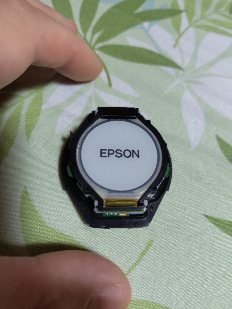
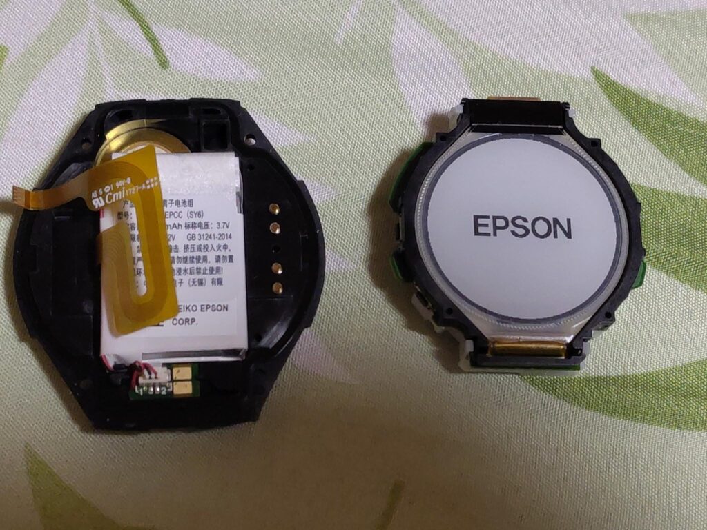
Epson J300 GPS Watch Disassembly

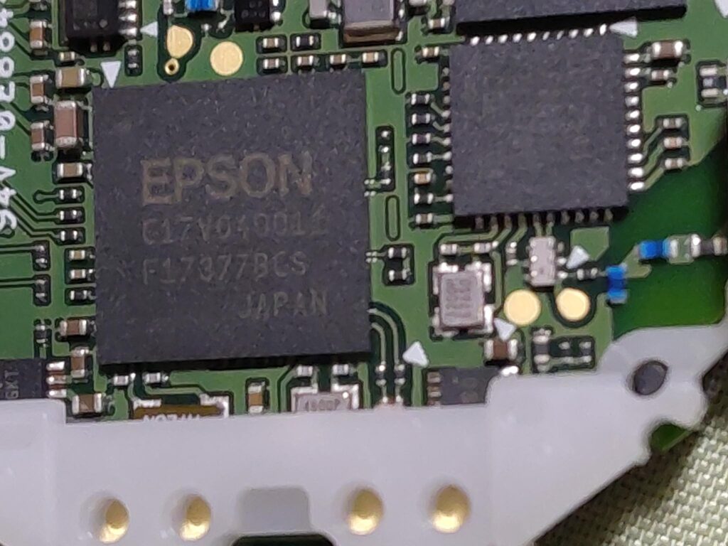
C17V04001, F17377BCS

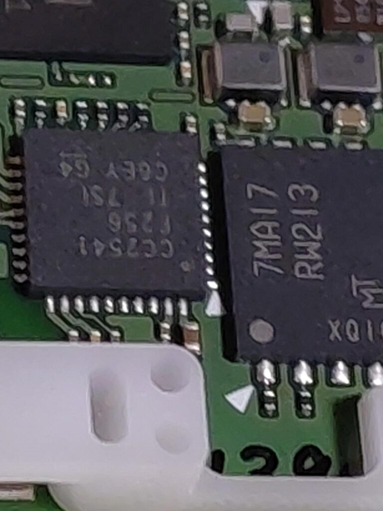
CC7541

7MA17, RM213

Display appears to be ET011TJ1

INHECO 96 Chick Brooder

Overview

The Inheco Control 96 is an OEM unit built around a Watlow Series 96 PID controller and a Watlow LSTW driver module, housed in an Inheco-branded chassis. Originally designed for TEC/Peltier temperature control in laboratory equipment (e.g. the Inheco CPAC Ultraflat for heating Eppendorf tubes), it can be repurposed as a general-purpose temperature controller.

This writeup documents repurposing one such unit to drive a Kotatsu heater element (~100V rated, operated at 30–40V) as a brooder heater for day-old chicks. The unit was acquired second-hand and arrived with a PIC microcontroller attached to the RS232 port and the controller in a misconfigured/locked state.

Reference also: 41j.com Inheco Control 96 Notes — confirms the LSTW is an undocumented OEM module, likely an H-bridge in the original TEC application, but in single-output configurations acts as a simple DC power switch.


Hardware

Watlow Series 96 PID Controller

  • 1/16 DIN panel mount PID controller
  • Universal input (thermocouple, RTD, process)
  • 4 outputs (configuration dependent on model)
  • RS232 serial communications on output 4 terminals (19, 20, 21)
  • Keys: ▲ Up, ▼ Down, ∞ Home/Infinity, ↺ Advance/Cycle
  • Firmware version on this unit: r7dL (visible in DIAG menu)

Watlow LSTW 1.5 Driver Module

  • Undocumented OEM module, not available on Watlow website
  • 8-terminal connector block
  • Functions as a DC power switch (not a true SSR)
  • Contains an IRF5305 P-channel MOSFET (55V, 31A rated) as the main switching element
  • Protection diode across input: originally B13 Schottky (30V, 1A — undersized)
  • Status LEDs: GRUN (green) = control input active, ROT (red) = output switching on

LSTW Terminal Pinout (as determined empirically)

PinsFunction
1–2Unknown / unused in this config
3–4Output to load (heater)
5–6Control input from Watlow 96 (24V DC signal)
7–8Connected to Watlow 96 rear center terminals (power/common)

The LSTW passes the supply voltage through to the load when the control signal is active — it does not have a separate mains input. Supply voltage = output voltage.

Kotatsu Heater Element

  • Rated 100V AC
  • Operated at 30–40V DC (sufficient for brooding temperatures)
  • Connected to LSTW output terminals 3–4

Thermocouple

  • Type J (blue/red wire, European IEC colour code)
  • Connected to Watlow 96 Input 1 terminals
  • Polarity sensitive — blue wire to negative terminal


Watlow Series 96 — Key Navigation

ActionKey Sequence
Home PagePress ∞ briefly
Operations PagePress ▲ + ▼ together (~3 sec)
Factory PageHold ∞ + ↺ together for 6 seconds
Setup PageHold ▲ + ▼ together for 6 seconds
Enter a menuPress ↺
Change value▲ / ▼
Confirm valuePress ↺

Some config settings appeared to be locked out at first. I’m not sure if I was just misunderstanding the config system or if I actually fixed this. There was a PIC connected to the RS232 input on the Watlow 96, this seemed to be processing a signal from a knob on the front of the unit. I disconnected this.


Configuring the Thermocouple Type

Accessing CIN1 (Calibration Input 1 Menu)

  1. Enter Config Page: hold  ▲+▼ for 6 seconds (it changes to one menu after 3s then again)
  2. Press ▼ to navigate to CIN1
  3. Press ↺ to enter
  4. Set the thermo couple type to H to K-type and J for J-type.

LSTW Diode Failure and Repair

What Happened

When attempting to supply ~40V DC to the LSTW input (to drive the Kotatsu heater at sufficient power), the protection diode B13 failed with visible smoke.

Root Cause

The B13 is a 30V, 1A Schottky diode — it is connected across the input terminals as a flyback/protection diode. Supplying 40V exceeded its 30V rating, causing it to fail.

The main switching MOSFET (IRF5305, P-channel, 55V/31A, TO-220 package) survived.

Repair

The blown B13 was removed. Unit was tested without it — functional short-term since the MOSFET is not switching at high frequency in this application, so flyback spikes are minimal.

Replacement diode found by scavenging: A D2S58 Schottky diode was recovered from scrap PCB.

D2S58 specifications: 80V, 2A — significantly better rating than the original B13 and well suited for this application.

Installation: Cathode (stripe) to positive input terminal. Solder across input terminals in same orientation as original B13.

The D2S58 replacement is an improvement over the original B13. If sourcing a new part, any Schottky diode rated ≥50V, ≥1A is suitable (e.g. 1N5819 at 40V is marginal; prefer SS34, 1N5822, or similar at 40V+).


Final Working Configuration

ParameterValue
Thermocouple typeJ type (J in CIN1)
Thermocouple wiringBlue = negative, Red = positive
LSTW control signal24V DC from Watlow 96 Output 1 (terminals top 3-pin block)
Supply voltage to LSTW~40V DC (Rigol DP832)
HeaterKotatsu element, connected to LSTW output terminals 3–4
LSTW protection diodeD2S58 (scrap), across input, cathode to positive
SetpointSet to desired brooding temperature (e.g. 35°C for day-old chicks)

Operational Notes

  • The GRUN LED on the LSTW indicates the 24V control signal is present and active
  • The ROT LED indicates the output is switching (heater powered)
  • If ROT is lit but no heat: check supply voltage is connected to LSTW and heater is connected to output terminals 3–4
  • ERR4 on the Watlow 96 = open sensor (thermocouple disconnected or broken) — check wiring at terminals 5, 6, 7
  • The controller PID will modulate output to maintain setpoint — allow time for auto-tuning to stabilise temperature control
  • A few degrees offset between reading and actual is normal with replacement thermocouples — a calibration offset can be added in the IN1 menu if accessible