Beckman DU530 Photospectrometer (Hach DR4000?) Photodiode Amplifier Board
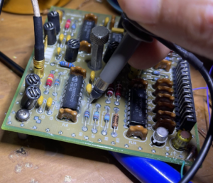
I wanted to do some basic experiments with the DU 530 UV-Vis Photospectrometer (see previous post) photodiode amplifier. In particular I wanted to confirm that they were running the diodes unbiased. I could have reassembled the unit and checked voltages, but I decided to test the photodiode board in isolation instead.
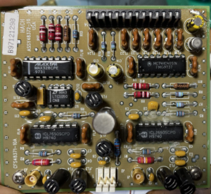
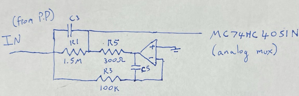
The board contains two seemingly identical (aside from the feedback resistor, the other uses a 180K instead of 1.5M) transimpedance amplifier circuits:
I was able to power up the opamps with +/- 10V. V- on pin 13 of the header, V+ on pin 9. I connected ground directly to the ground plain on the top of the board. By inputting a test signal (function generator output through a 100M resistor) I was able to measure low frequency current with the amplifier. The bandwidth seem very limited (few 100Hz?) but I didn’t accuracy characterize the board, and in any case things were quite noisy as I wasn’t using any shielding.
But the output was clean enough to get a rough sense of what was going on (and was as expected, inverted):
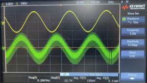
There are a few differences between the layout here and the basic transimpedance layout. R1 seems to be providing the bulk of the gain, C3 should limit peaking. Don’t fully understand why R3 and R5 are required. The output from the amplifier heads out to an analog mux. The board has 3 opamps (one for each photodiode, and IIRC there’s a header which connects to a temperature sensor). So this mux no doubt selects the opamp output to go to the header. From looking at the main PCB, it seemed like pin 14 went to the ADC on the main board. But I have no plans to further investigate this side of the circuit at this point.