HP Interferometer Notes
I’ve been setting up an interferometer. I purchased the system from siliconsam (of Sam’s lasers) on eBay (this is the auction). He occasionally sells old HP systems on eBay, the advantage is that the laser, optics and receiver come tested.
There is however “some assembly required”. In particular, this kit is based around the µMD1. This is essential a Chipkit DP32 (PIC32 dev board), with some firmware Sam and Jan Beck and a Windows application (written in VB).
The instructions for wiring the Chipkit DP32 are pretty straightforward. The only issue I had was that the diagrams only show the resistor color codes, this is a problem for me as I’m colorblind. However there are 6 of one type and two of the other so it was easy enough to figure out from the parts provided. At some point I’d like to design a custom PCB to avoid all the wirewrapping…
You also have to wire up the optical receiver and laser head cables. Notes on these are below.
10780A Optical Receiver Wiring
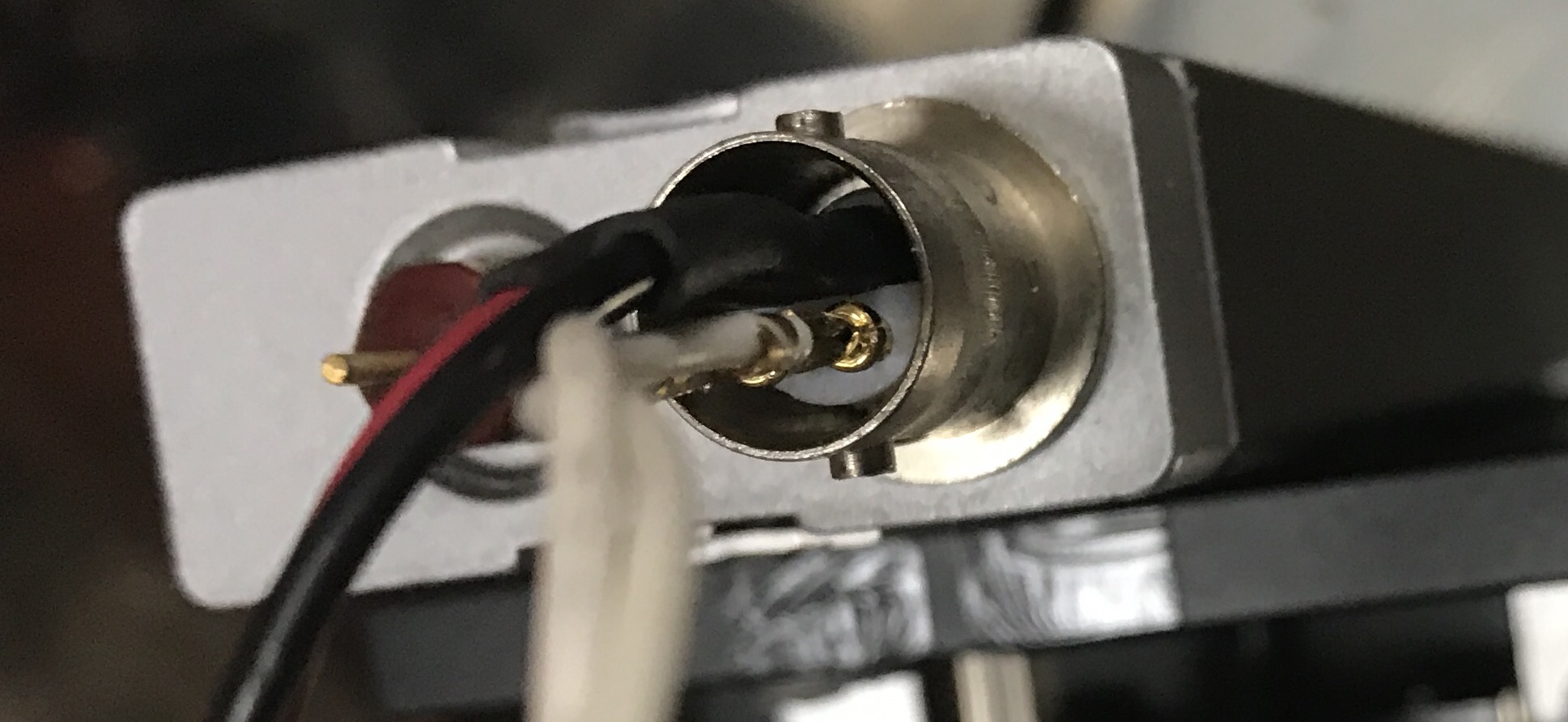
The optical receive uses a strange connector. I’ve seen this called a “quad BNC” (also seems to be called 4-pin BNC) and it is a bayonet style connector with 4 internal conductors. Sam’s kit provides cables wired with pins which you prod into the connector, it’s not the most robust solution in the world, but it holds together pretty well.
The 10780A documentation provides the following wiring information:
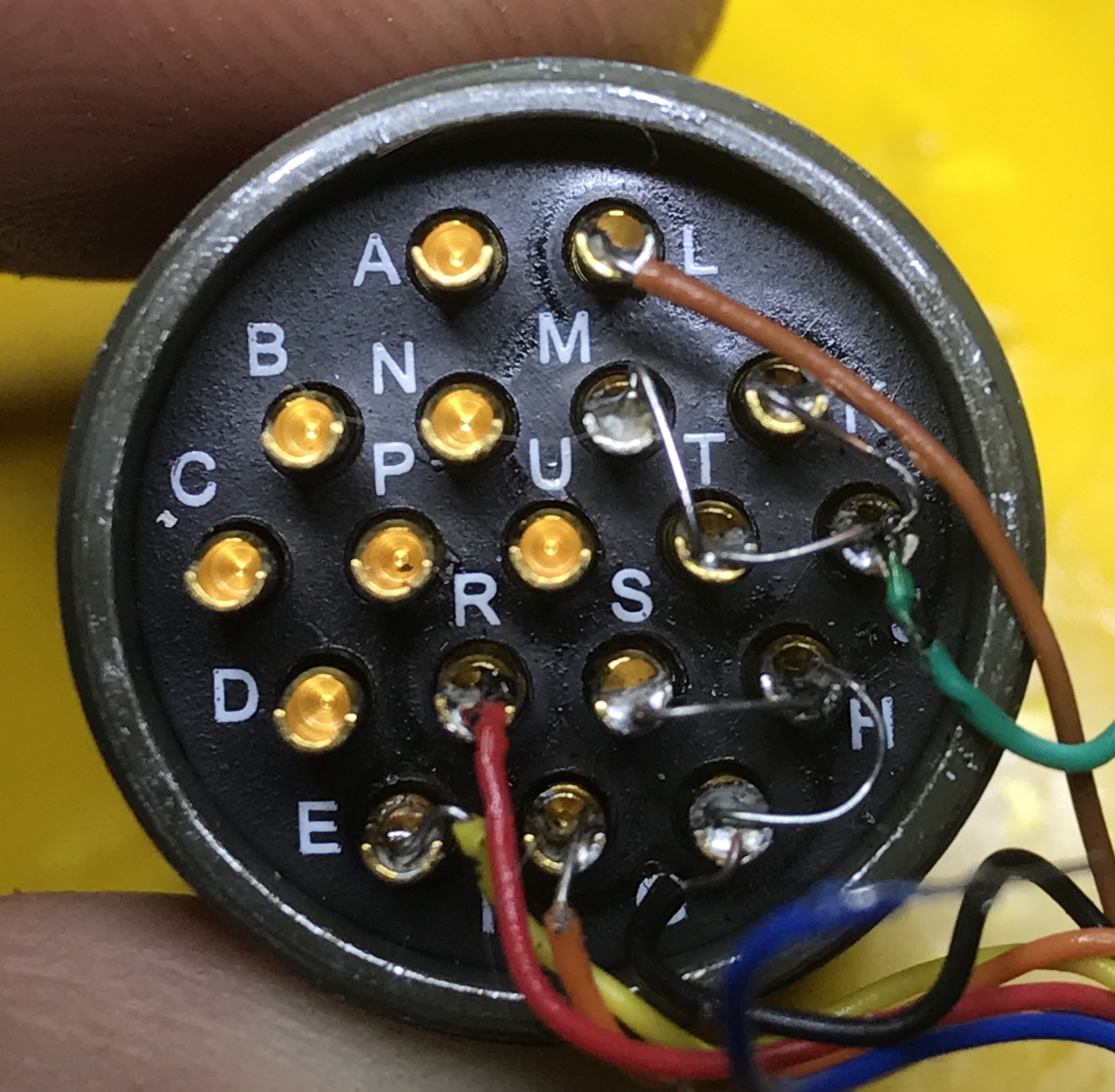
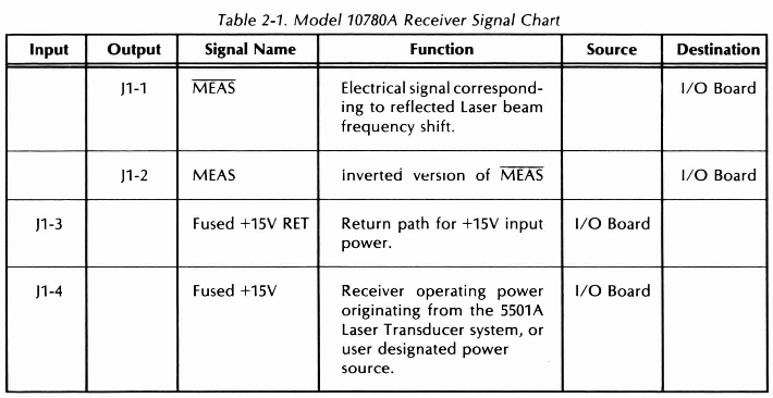 “Fused +15V RET” is essentially ground. The wiring I used is show below. It can also be found on Sam’s FAQ.
5517B Laser head Wiring
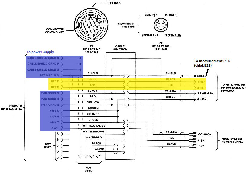
The laser head uses an old multiconductor connector. I think this one. You can find details of the wiring of this connector in the 5517 manual (5517 manual local copy). I’ve also highlighted the wiring of this cable on the screenshot below.
That’s it for now. I have a couple of videos on youtube documenting the setup:
At some point in the future I may post more details of the laser alignment process, and the jigs I’ve designed to try and make alignment easier.