esp8266 XBee carrier board PCB design
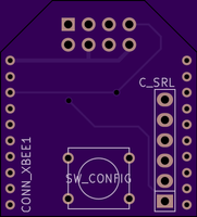
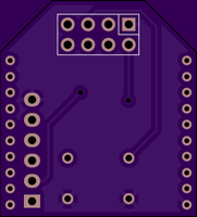
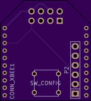
I’ve been putting together a small carrier board to allow a esp8266 board to sit on an XBee connector. The design is shown above (as yet untested). The gerbers and Kicad design files are available for download below.
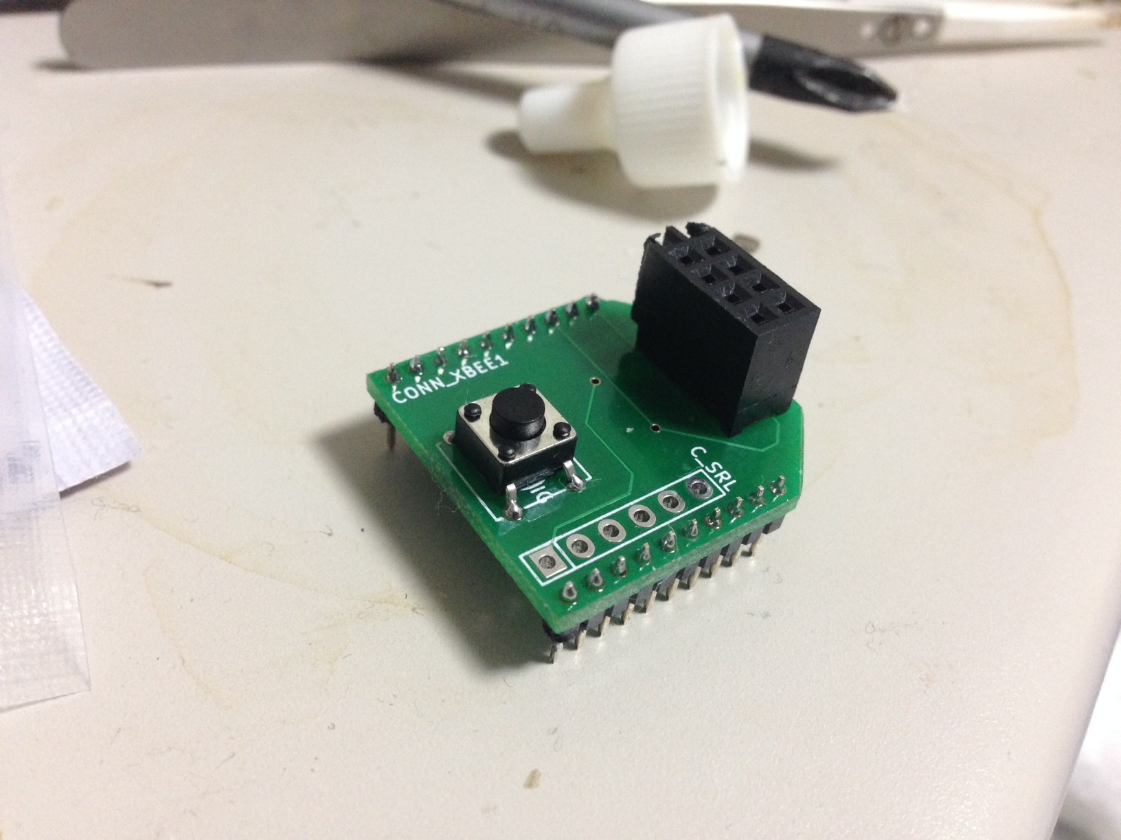
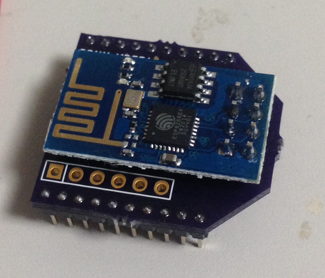
UPDATE: The first rev of these boards came though, I’ll be needing to update the design. The esp1 faces in the opposite direction to what I’d like. The serial TX and RX connections are connected the wrong way to the FTDI header (which doesn’t matter too much as it’s just there for debugging). The fit into the XBee header also seems poor, I’m not sure if this is just because I’ve killed the header I’m using by jamming 2.54mm pins into it. Here the a couple of pics in any case:
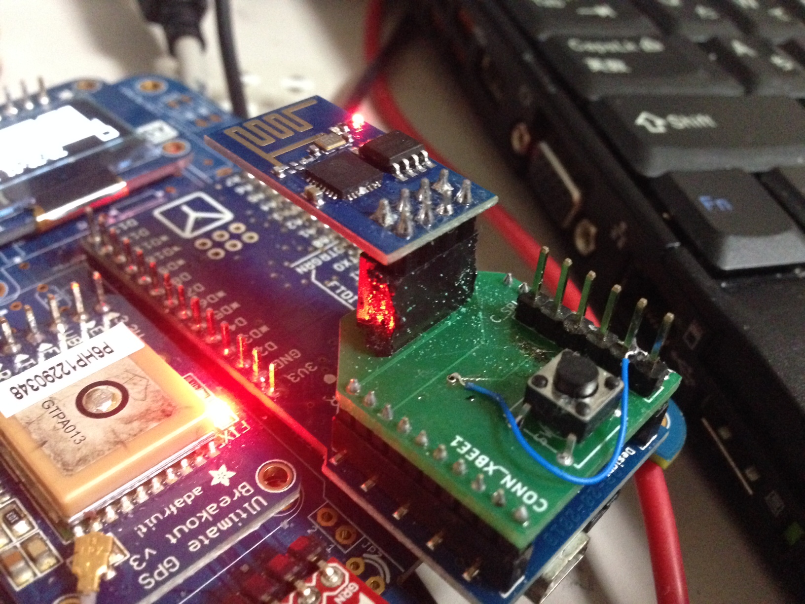
UPDATE: Sent out a rev with the header flipped. Wanted to get it out before I go away to China. Here are the pics:
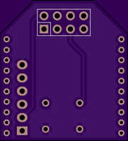
And the new gerbers: gerbers
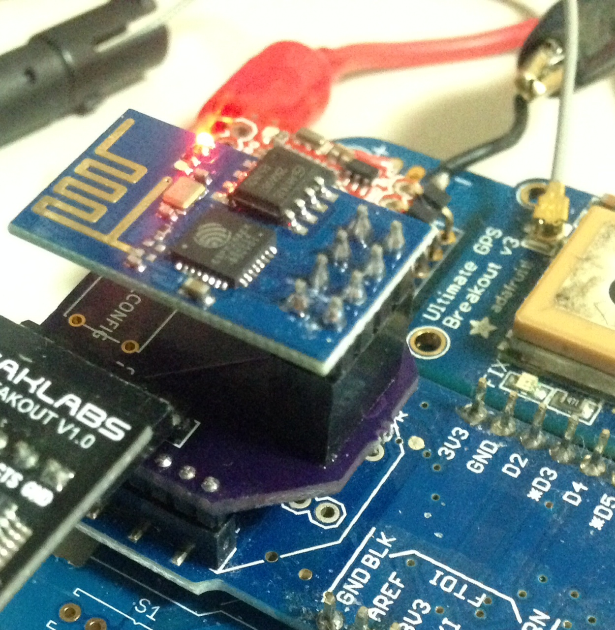
UPDATE2: The new boards came back, and I’ve now tested them all looks good! Pics below:
This looks really neat!. I’m using one of these boards http://shop.ciseco.co.uk/xrf-relaybase-also-for-xbee-wireless-dual-relay-module-for-switching-kit/ and would like to convert an esp8266-esp1 rather than have wires hanging out!. Are they for sale?
Hi Tony, I’m planning to put them up for sale at some point (possibly on tindle). Probably for a nominal cost, something like 1GBP + postage. If you’re interested send me a male (new at sgenomics dot org).