Random Notes 2
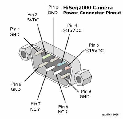
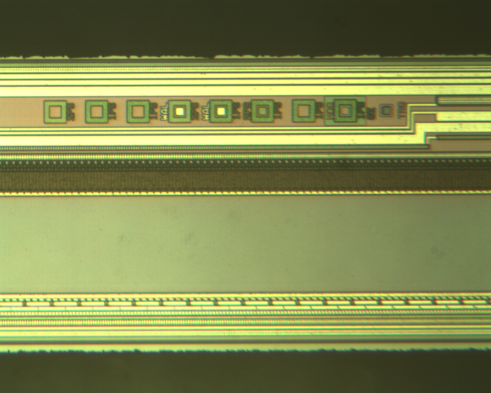
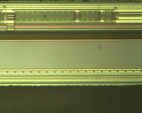
Hiseq 2000 TDI
Serial number from one module: C10000-515, 661675.
aslver.exe dump from my cameras:
1: AS-PHX-D48CL-PE1
Grabber HW Version 9.10.00
Grabber SW Version 5.58.24
Library FW Version 9.10.00
Grabber Connection PCIe x1
Camera Connected Unknown
Camera Name C10000-515
Camera S/N S/N: 661694
Camera Version INF 2.01-F20-R02
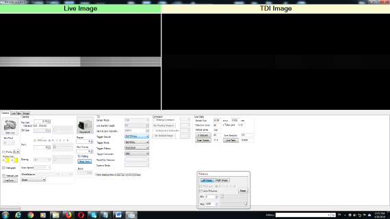
1x PCIe card appears to work. 4x PCIe doesn’t show up on aslver.exe as yet.
Trigger was plugged into SMA port on board, driven by function generator 5V input.
Cameralink cable plugged into top port (furthest from motherboard) on the PCIe cameralink acquisition board.
HP C6602
http://nicholasclewis.com/projects/inkshield/
LinearCCDs
http://www.advancedmems.com/pdf/AMEMS_LineSensorArraySummary_v1.pdf
S11639 CMOS made by Hamamatsu
ILX511:
LSH6008-CA10A
Same as in Epson printers?
Stuff from, https://twitter.com/steubens7/status/1179848585636126720
nope, this little shoulder is the black level / zero value, iirc there was another 3 volts or so before saturation.
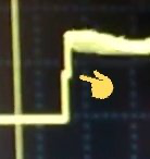
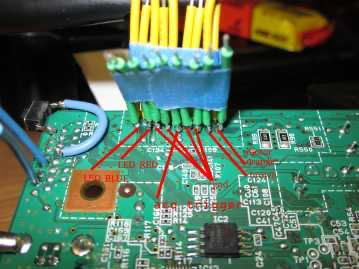
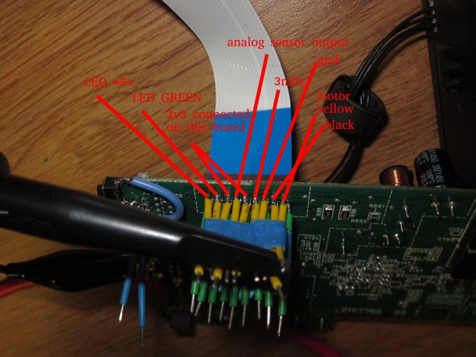
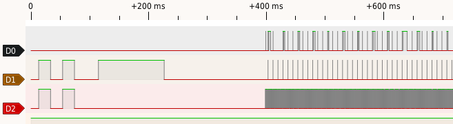
top trace is analog output, second trace is the trigger, bottom trace is the clock that cycles samples out after trigger, the short pulses on the trigger line were sample every 32 elements in the scan head or something:
https://gist.github.com/ohsix/4f518a2080dc913f880273fc80e04f52
| #include <Arduino.h> | |
| #include <ports.h> | |
| #include <base.h> | |
| #include <DirectIO.h> | |
| #include <Adafruit_NeoPixel.h> | |
| #include <TimerOne.h> | |
| #define CLKPIN TIMER1_A_PIN | |
| #define TRGPIN 4 | |
| #define DEBUGPIN 6 | |
| #define FIRSTFIELD 7 | |
| #ifndef cbi | |
| #define cbi(sfr, bit) (_SFR_BYTE(sfr) &= ~_BV(bit)) | |
| #endif | |
| #ifndef sbi | |
| #define sbi(sfr, bit) (_SFR_BYTE(sfr) |= _BV(bit)) | |
| #endif | |
| Output<TRGPIN> trg; | |
| Output<CLKPIN> clk; | |
| Output<6> dbg; | |
| Output<FIRSTFIELD> ff; | |
| #define NUMPIXELS 8 | |
| #define NEO_PIN 8 | |
| Adafruit_NeoPixel pixels = Adafruit_NeoPixel(NUMPIXELS, NEO_PIN, NEO_RGB + NEO_KHZ800); | |
| const uint8_t PROGMEM gamma8[] = { | |
| 0, 0, 0, 0, 0, 0, 0, 0, 0, 0, 0, 0, 0, 0, 0, 0, | |
| 0, 0, 0, 0, 0, 0, 0, 0, 0, 0, 0, 0, 1, 1, 1, 1, | |
| 1, 1, 1, 1, 1, 1, 1, 1, 1, 2, 2, 2, 2, 2, 2, 2, | |
| 2, 3, 3, 3, 3, 3, 3, 3, 4, 4, 4, 4, 4, 5, 5, 5, | |
| 5, 6, 6, 6, 6, 7, 7, 7, 7, 8, 8, 8, 9, 9, 9, 10, | |
| 10, 10, 11, 11, 11, 12, 12, 13, 13, 13, 14, 14, 15, 15, 16, 16, | |
| 17, 17, 18, 18, 19, 19, 20, 20, 21, 21, 22, 22, 23, 24, 24, 25, | |
| 25, 26, 27, 27, 28, 29, 29, 30, 31, 32, 32, 33, 34, 35, 35, 36, | |
| 37, 38, 39, 39, 40, 41, 42, 43, 44, 45, 46, 47, 48, 49, 50, 50, | |
| 51, 52, 54, 55, 56, 57, 58, 59, 60, 61, 62, 63, 64, 66, 67, 68, | |
| 69, 70, 72, 73, 74, 75, 77, 78, 79, 81, 82, 83, 85, 86, 87, 89, | |
| 90, 92, 93, 95, 96, 98, 99,101,102,104,105,107,109,110,112,114, | |
| 115,117,119,120,122,124,126,127,129,131,133,135,137,138,140,142, | |
| 144,146,148,150,152,154,156,158,160,162,164,167,169,171,173,175, | |
| 177,180,182,184,186,189,191,193,196,198,200,203,205,208,210,213, | |
| 215,218,220,223,225,228,231,233,236,239,241,244,247,249,252,255 }; | |
| void setup() { | |
| analogReference(EXTERNAL); | |
| pinMode(CLKPIN, OUTPUT); | |
| //pinMode(DEBUGPIN, OUTPUT); | |
| Timer1.initialize(1); // ~1mhz | |
| Timer1.pwm(CLKPIN, 512); // 50% duty cycle | |
| Timer1.stop(); | |
| pinMode(TRGPIN, OUTPUT); | |
| pinMode(A0, INPUT); | |
| pinMode(ledToPin(0), OUTPUT); | |
| pinMode(ledToPin(1), OUTPUT); | |
| pinMode(ledToPin(2), OUTPUT); | |
| Serial.begin(115200); | |
| cbi(ADCSRA, ADPS0); | |
| cbi(ADCSRA, ADPS1); | |
| cbi(ADCSRA, ADPS2); | |
| sbi(ADCSRA, ADPS1); | |
| // Serial.print("prescaler = "); | |
| // Serial.println(ADCSRA & 0xE0); | |
| pixels.begin(); | |
| } | |
| int avgRead(int port, int samples) | |
| { | |
| int i; | |
| long reading = 0; | |
| for(i = 0; i < samples; i++) | |
| { | |
| reading += analogRead(port); | |
| } | |
| reading /= samples; | |
| return reading; | |
| } | |
| void clockCycle(int pin, int count) | |
| { | |
| while(count–) | |
| { | |
| digitalWrite(pin, HIGH); | |
| digitalWrite(pin, LOW); | |
| } | |
| } | |
| int ledToPin(int color) | |
| { | |
| switch(color) | |
| { | |
| case 0: // red | |
| return 2; | |
| break; | |
| case 1: // green | |
| return 3; | |
| break; | |
| case 2: // blue | |
| return 5; | |
| break; | |
| } | |
| } | |
| void ledOn(int color) | |
| { | |
| digitalWrite(ledToPin(color), LOW); | |
| } | |
| void ledOff(int color) | |
| { | |
| digitalWrite(ledToPin(color), HIGH); | |
| } | |
| void ledsOn() | |
| { | |
| for(int i = 0; i <= 2; i++) | |
| ledOn(i); | |
| } | |
| void ledsOff() | |
| { | |
| for(int i = 0; i <= 2; i++) | |
| ledOff(i); | |
| } | |
| // returns n samples from start of readback to end of readback | |
| void readLine(byte* output, int samples) | |
| { | |
| int zeroLevel; | |
| int blackLevel; | |
| int clocks; | |
| int i; | |
| int samplePos = 2593 / samples; | |
| int currSample = 0; | |
| shiftOut(TRGPIN, CLKPIN, MSBFIRST, 0xF0); // trigger pulse and slow clock | |
| // lock step through front porch with slow clock in order to capture reference levels without unpredictable jitter | |
| clockCycle(CLKPIN, 4); | |
| // sample black level | |
| for(i=0; i < 3; i++) | |
| { | |
| clocks=5; while(clocks–) | |
| { | |
| clk=1; | |
| clk=0; | |
| } | |
| blackLevel += avgRead(A0, 3); | |
| } | |
| blackLevel /= 3; | |
| // Serial.print("blackLevel = "); | |
| // Serial.println(blackLevel); | |
| // 65 more clock cycles until analog goodies | |
| clocks = 65; while(clocks–) | |
| { | |
| clk=1; | |
| clk=0; | |
| } | |
| #define ANALOG_CLOCKS (12 * 216 + 1) | |
| int stepSpacing = ANALOG_CLOCKS / samples; | |
| int nextSample = 0; | |
| // go through analog bins | |
| for(i = 0; i < 12 * 216 + 1; i++) | |
| { | |
| clk = 1; | |
| if(nextSample– == 0) | |
| { | |
| dbg=1; | |
| nextSample = stepSpacing; | |
| // output[currSample++] = map(avgRead(A0, 5), blackLevel, 1024, 0, 255); | |
| output[currSample++] = map(analogRead(A0), blackLevel, 1024, 0, 255); | |
| dbg=0; | |
| } | |
| clk = 0; | |
| } | |
| #if 0 | |
| for(i = 0; i < 2593; i++) | |
| { | |
| clk =1; | |
| clk =0; | |
| } | |
| #endif | |
| } | |
| void loop() { | |
| int led = 0; | |
| byte samples[64]; | |
| byte redSamples[NUMPIXELS]; | |
| byte greenSamples[NUMPIXELS]; | |
| byte blueSamples[NUMPIXELS]; | |
| int i; | |
| ff=1; | |
| ff=0; | |
| #if 1 | |
| ledOn(0); | |
| readLine(redSamples, NUMPIXELS); | |
| ledsOff(); | |
| ledOn(1); | |
| readLine(greenSamples, NUMPIXELS); | |
| ledsOff(); | |
| ledOn(2); | |
| readLine(blueSamples, NUMPIXELS); | |
| ledsOff(); | |
| #endif | |
| #if 0 | |
| for(led = 0; led < 0; led++){ | |
| ledOn(led); | |
| readLine(samples, 4); | |
| ledOff(led); | |
| } | |
| ledsOff(); | |
| #endif | |
| for(i = 0; i < NUMPIXELS; i++) | |
| { | |
| #if 0 | |
| Serial.print("sample["); | |
| Serial.print(i); | |
| Serial.println("] = "); | |
| Serial.print("red "); | |
| Serial.println(redSamples[i]); | |
| Serial.print("green "); | |
| Serial.println(greenSamples[i]); | |
| Serial.print("blue "); | |
| Serial.println(blueSamples[i]); | |
| #endif | |
| pixels.setPixelColor(i, pixels.Color(pgm_read_byte(&gamma8[greenSamples[i]]), pgm_read_byte(&gamma8[redSamples[i]]), pgm_read_byte(&gamma8[blueSamples[i]]))); | |
| // pixels.setPixelColor(i, pixels.Color(0, 0, 0)); | |
| // pixels.setPixelColor(i, pixels.Color(redSamples[i], greenSamples[i], blueSamples[i])); | |
| // pixels.setPixelColor(i, pixels.Color(pgm_read_byte(&gamma8[redSamples[i]]), pgm_read_byte(&gamma8[greenSamples[i]]), pgm_read_byte(&gamma8[blueSamples[i]]))); | |
| // pixels.setPixelColor(i, pixels.Color(pgm_read_byte(&gamma8[redSamples[i]]), pgm_read_byte(&gamma8[redSamples[i]]), pgm_read_byte(&gamma8[redSamples[i]]))); | |
| pixels.show(); // This sends the updated pixel color to the hardware. | |
| } | |
| // delay(100); | |
| //delayMicroseconds(100); | |
| } | |
| void old_loop() { | |
| int bin; | |
| int i; | |
| int samples[12]; | |
| int clocks; | |
| int zeroLevel; | |
| int blackLevel; | |
| static int led=0; | |
| //shiftOut(TRGPIN, CLKPIN, MSBFIRST, 0); | |
| dbg=1; | |
| zeroLevel = avgRead(A0, 5); | |
| // zeroLevel = analogRead(A0); | |
| dbg=0; | |
| dbg=1; | |
| shiftOut(TRGPIN, CLKPIN, MSBFIRST, 0xF0); // trigger pulse and slow clock | |
| dbg=0; | |
| // lock step through front porch with slow clock in order to capture reference levels without unpredictable jitter | |
| dbg=1; | |
| clockCycle(CLKPIN, 4); | |
| dbg=0; | |
| dbg=1; | |
| for(i=0; i < 3; i++) | |
| { | |
| clocks=5; while(clocks–) | |
| { | |
| clk=1; | |
| clk=0; | |
| } | |
| blackLevel += avgRead(A0, 3); | |
| } | |
| blackLevel /= 4; | |
| // Serial.print("blackLevel = "); | |
| // Serial.println(blackLevel); | |
| dbg=0; | |
| if(led == 0){ | |
| ff = 1; | |
| ff = 0; | |
| } | |
| ledOn(led); | |
| //ledsOn(); | |
| dbg=1; | |
| clocks = 40; while(clocks–) | |
| { | |
| clk=1; | |
| clk=0; | |
| } | |
| dbg=0; | |
| for(i = 0; i < 350*8; i++) | |
| { | |
| clk =1; | |
| clk =0; | |
| } | |
| dbg =1; | |
| dbg=0; | |
| // Timer1.pwm(CLKPIN, 512); // fast clock | |
| /* dbg=1; | |
| for(i = 0; i < 300; i++) | |
| { | |
| samples[i] = analogRead(A0); | |
| //delayMicroseconds(2000); | |
| } | |
| dbg=0; | |
| */ | |
| // sample front porch reference level 2 clocks later, for 80 hs clocks | |
| // sample bins 83 clocks after fast start | |
| // bins seem to be 215 clocks wide, 12 bins, 1 clock per pixel | |
| //delayMicroseconds(1); | |
| #if 0 | |
| dbg=1; | |
| noInterrupts(); | |
| while(analogRead(A0) -5 < zeroLevel) | |
| ; | |
| interrupts(); | |
| // wait for voltage to increase to follow clock jitter | |
| dbg=0; | |
| #endif | |
| dbg = 1; | |
| blackLevel = avgRead(A0, 5); | |
| // blackLevel = analogRead(A0); | |
| dbg = 0; | |
| #if 0 | |
| noInterrupts(); | |
| while(analogRead(A0) -10< blackLevel) | |
| { | |
| dbg=1; | |
| delayMicroseconds(0); | |
| dbg=0; | |
| } | |
| ; | |
| interrupts(); | |
| #endif | |
| dbg = 1; | |
| delayMicroseconds(1); | |
| dbg = 0; | |
| /* | |
| delayMicroseconds(100); | |
| dbg=1; | |
| bin= analogRead(A0); | |
| dbg=0; | |
| */ | |
| // delayMicroseconds(2670); | |
| Timer1.stop(); | |
| digitalWrite(CLKPIN, LOW); | |
| /* | |
| Serial.print("zeroLevel = "); | |
| Serial.println(zeroLevel); | |
| Serial.print("blackLevel = "); | |
| Serial.println(blackLevel); | |
| /* Serial.print("bin = "); | |
| Serial.println(bin); | |
| */ | |
| //delay(50); | |
| #if 1 | |
| ledOff(led); | |
| // switch LED | |
| if(++led > 2) | |
| led = 0; | |
| #endif | |
| //ledsOff(); | |
| // Serial.println(led); | |
| // Serial.print("normalized = "); | |
| // Serial.println(map(bin – blackLevel, zeroLevel, 1024, 0, 255)); | |
| //delay(10); // inter line delay | |
| delayMicroseconds(100); | |
| } |
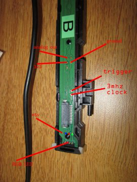
| the scan head expects a trigger, then a clock, analog values come out on one of the pins during the clocking | |
| the first few elements are from dark elements so you can use them as a reference | |
| sketch reads the 3 full color fields and renders them on a ws2812b strip | |
| these are supposed to be in close contact with paper or something, but it works ok to about 4 inches (can resolve space between fingers) |
Magnetic Tape
DLT IV Fujifilm: ~10um.
3490E: 18um.