Astable multivibrator oscillator and a little oscillator history
After making a simple oscillator using a relay yesterday. I decided to move on to transistors today. This mirrors the technological development of oscillators. The original oscillators used in radio transmission were based on spark caps. A capacitor would charge for a DC supply until it built up enough potential to jump a spark gap allowing the current to discharge and the whole process to start again:
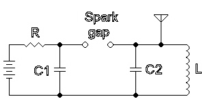
While I’ve seen referencing say they could reach MHz speeds with spark gaps (which surprises me!) it seems unlikely that they were particularly reliable, the resulting signal was obviously far from a clean sine wave. For this reason radio transmission oscillators migrated briefly to a more typical electromechanical approach, alternators!
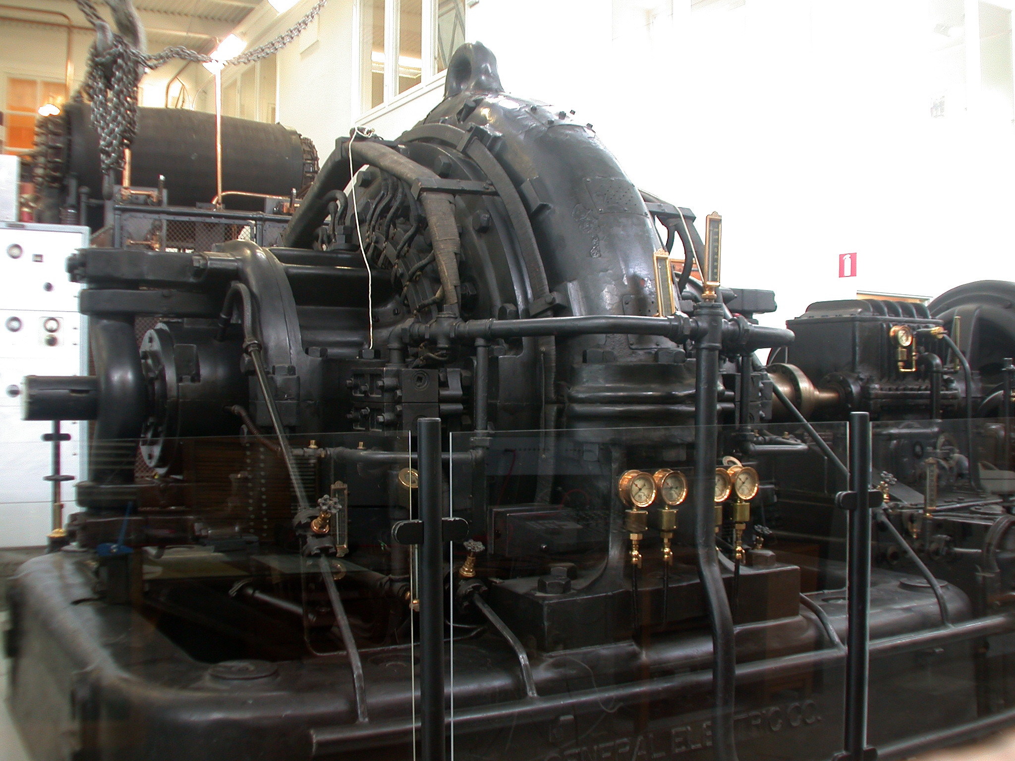
The wikipedia page is hugely informative, and describes alternators producing frequencies up to a 100Khz! Some of which were still in operation in the 1950s.
However, their useful life was rather brief, as these oscillators were quickly replaced by active valve and transistors designs.
So today I decided to look at the Astable multivariator, a 2 transistor oscillator. Wikipedia provides the schematic below:
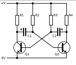
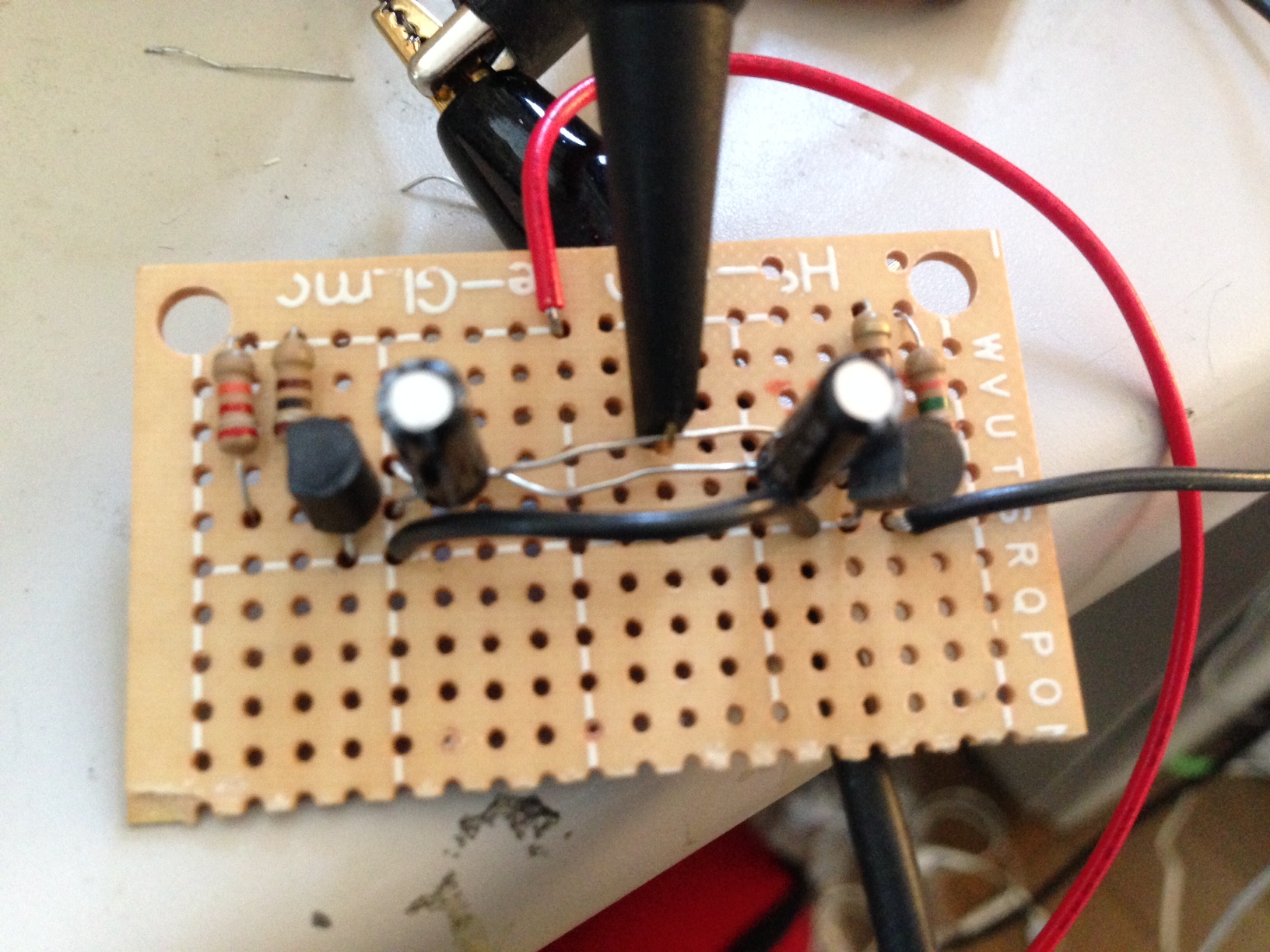
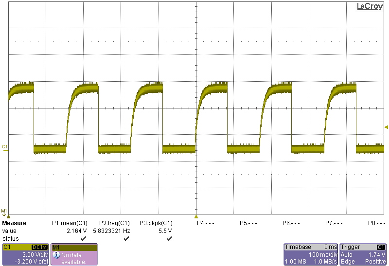
Which I put together using a 2N3904. I used a 100uF capacitor and 200Ohm and 1.2K resistors. This resulted in a frequency of ~6Hz. Which given the frequency determining equation derived on the wikipedia page of f=0.72/RC is approximately correct.
My basic understanding of the circuit is as follows. You can basically ignore R1 and R4, they simply limit the current going through the transistor, and into the capacitors (see note [1]). They are relatively small values (as compared with R2 and R3). When power is applied, one of Q1 or Q2 will be conducting more than the other. When the transistor conducts, it allows the capacitor on it’s base to charge up very quickly though that small resistor. This makes the other side of the capacitor negative with respect to ground (e.g. -5V if you’re using a 5V supply). This strong negative potential forces the other transistor open. The negative charge on the capacitor slowly discharges through the larger resistor (R2/R3), equalizing the charge on both sides of the capacitor. As this negative potential discharges, it rises above the transistors transition voltage and allows the other transistor to start conducting. It’s transistor now charges up very quickly, forcing a negative potential onto it’s other side, making the other transistor an open circuit and starting the process all over again.
Hopefully the following iCircuit spice simulation also makes things clear (you can download the iCircuit file here).
I also liked this video, it helped me a lot:
[1] This is probably a wrong interpretation, see my EEstackexchange question.