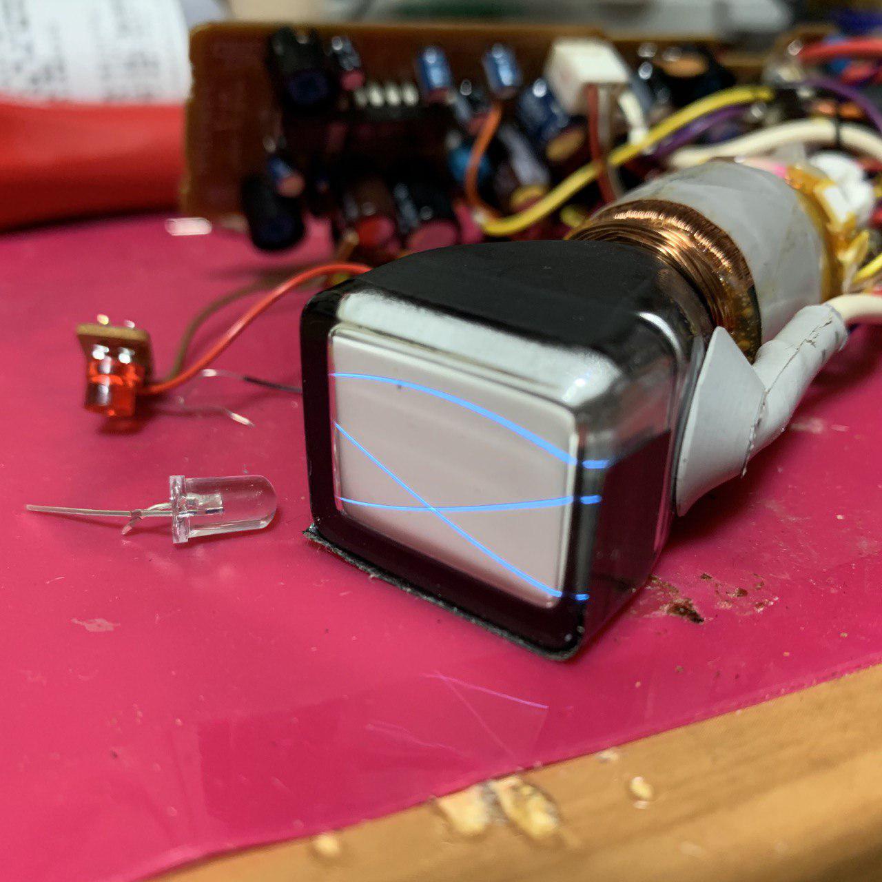
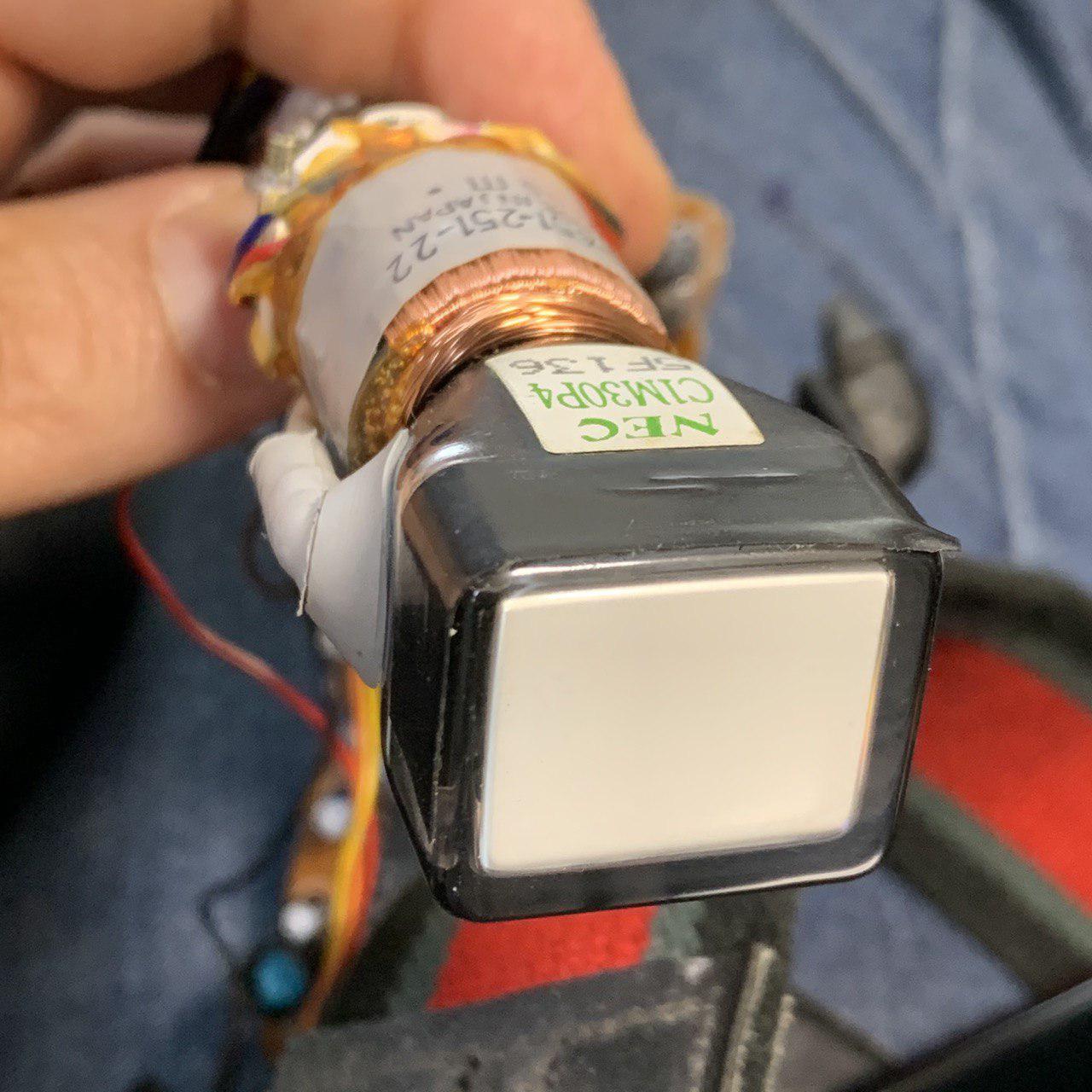
Sony CCD-V8AF Video Camera Recorder – Viewfinder CRT Notes

The viewfinder CRT from this video camera is a bit harder to interface with generate an X/Y input for. While the vertical can be driven with +/- 10V from a function generator, the horizontal requires higher voltages.
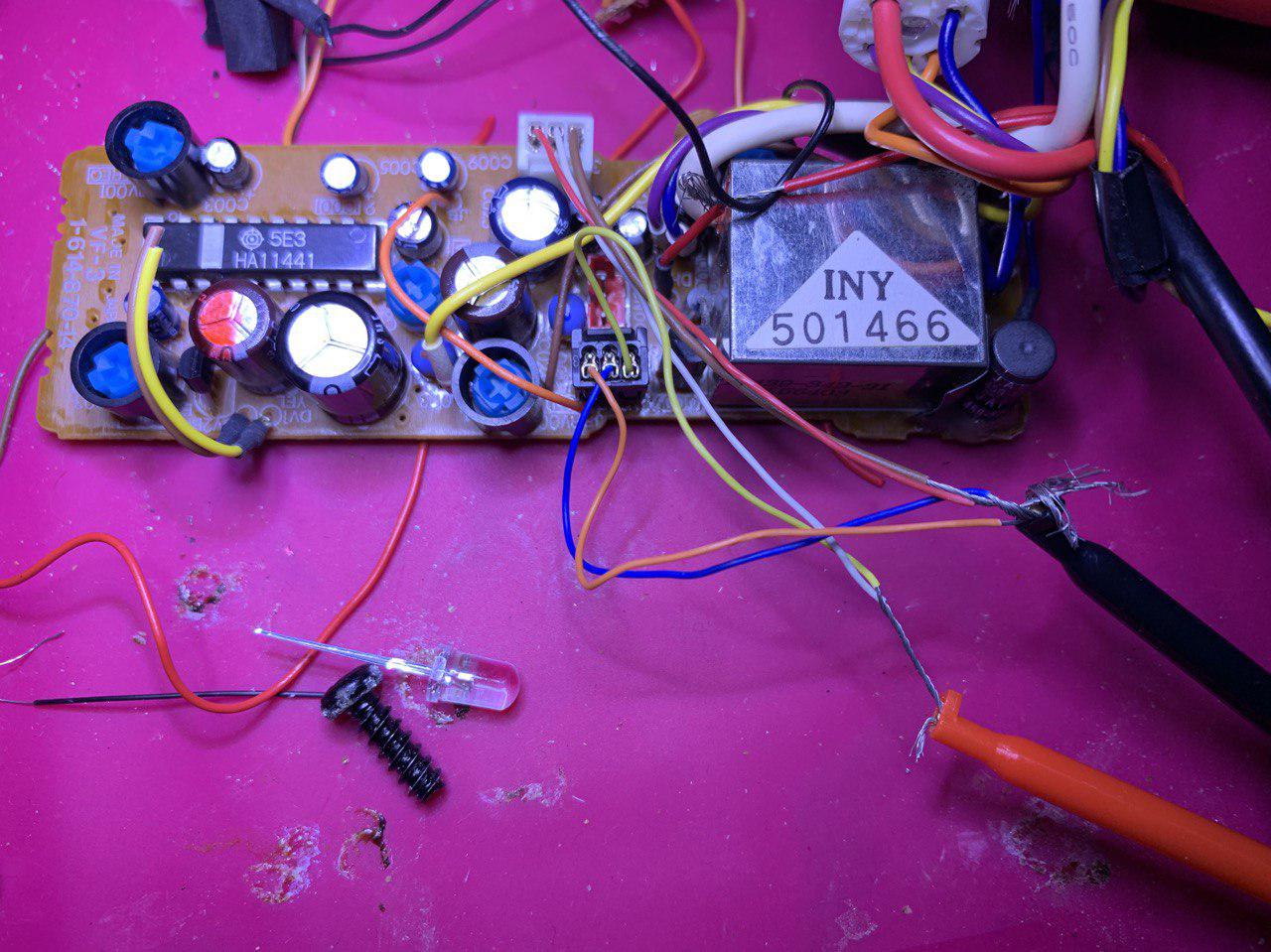
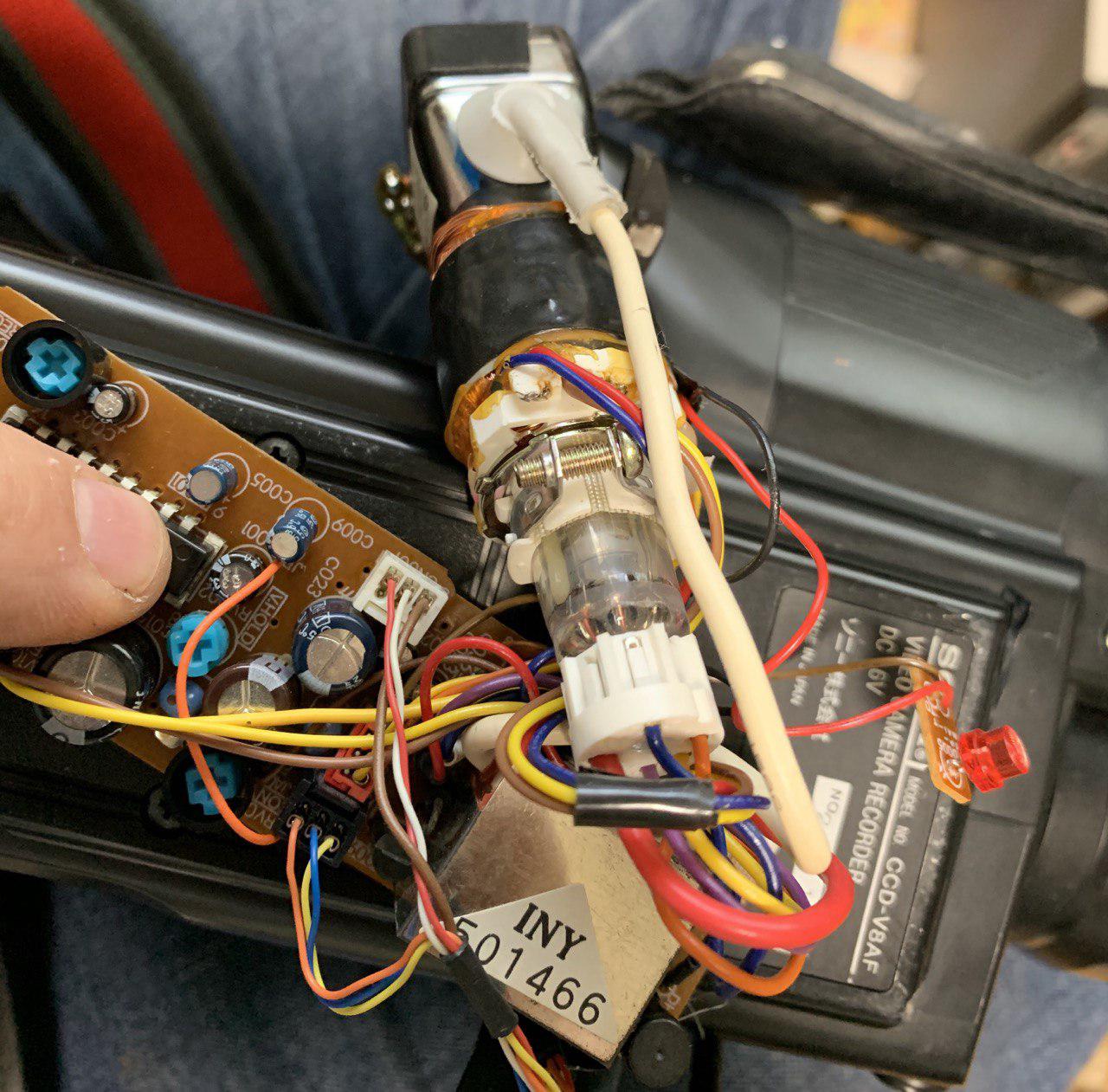
As for the modules previously described, this also takes a 5v input ~100mA. A few other lines need to be pulled up/down to get the CRT to start. Wiring is shown below:

The problem with this board that the horizontal requires ~30v, so you need to source this from somewhere. On the board, this is generated by an inductor (bottom right in the image above). The inductor is fed with 5v. There’s a transistor a (Q009) which I think probably creates a path to ground for this inductor causing a short voltage spike (which hits ~30v). This is what appears to drive the horizontal deflection on this board.
Because of the way it’s generated, it’s not possible to re-purpose the circuitry to amplify an input signal to drive the horizontal deflection… so an external amplifier etc. will be required.
Update: This is now working fine with +/- 6v (H?) and +/-3v. Q009 in addition to controlling the H sweep also seems to turn the beam on/off. However… I fiddled with the pot in the top left and everything seems to be working fine. I also removed the inductor… but I don’t think this is necessary. So it was probably working… just dim all the time.
Depending on the drive frequency, you can see the beam cut out. I’m wondering if it’s possible to just leave the beam on all the time, but the HV generator may not be designed to do this….

