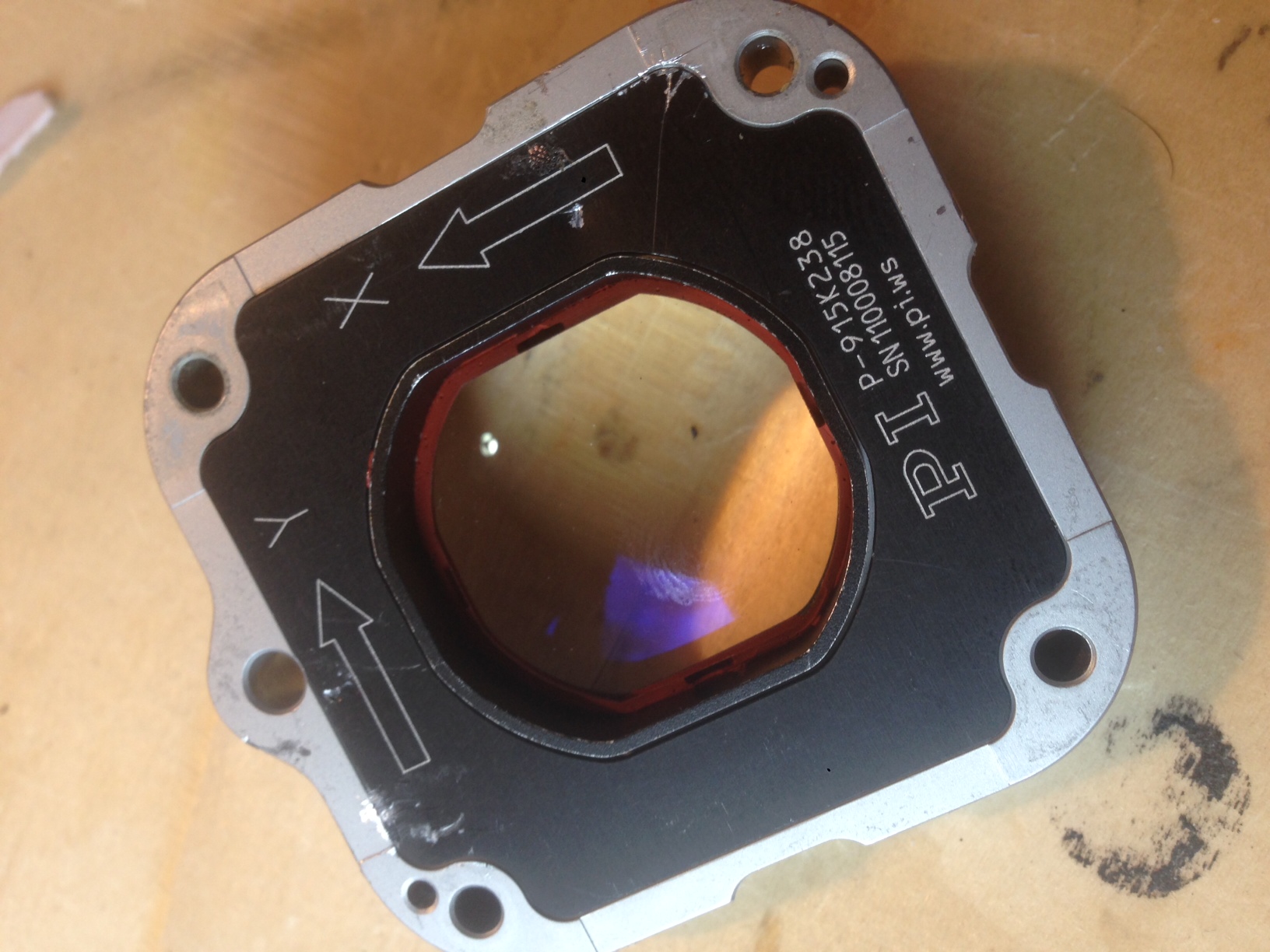
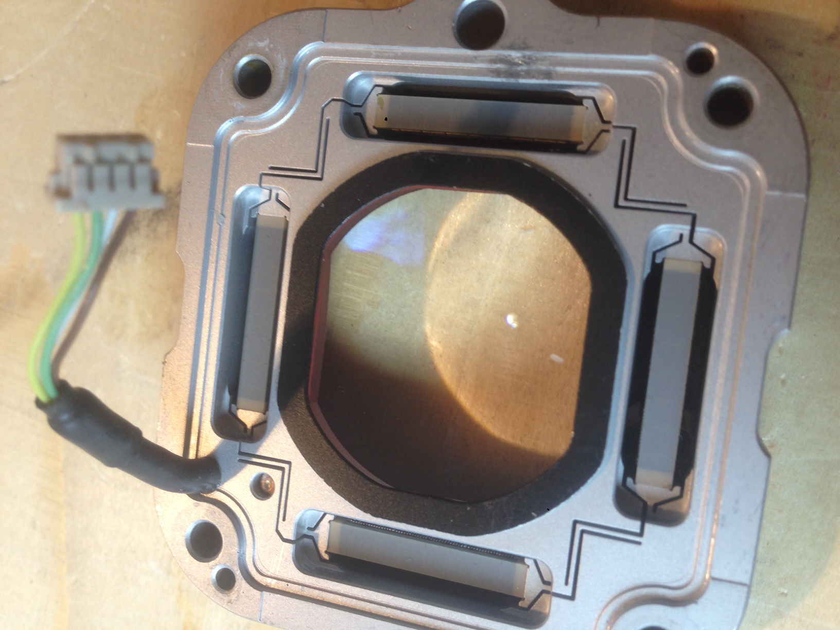
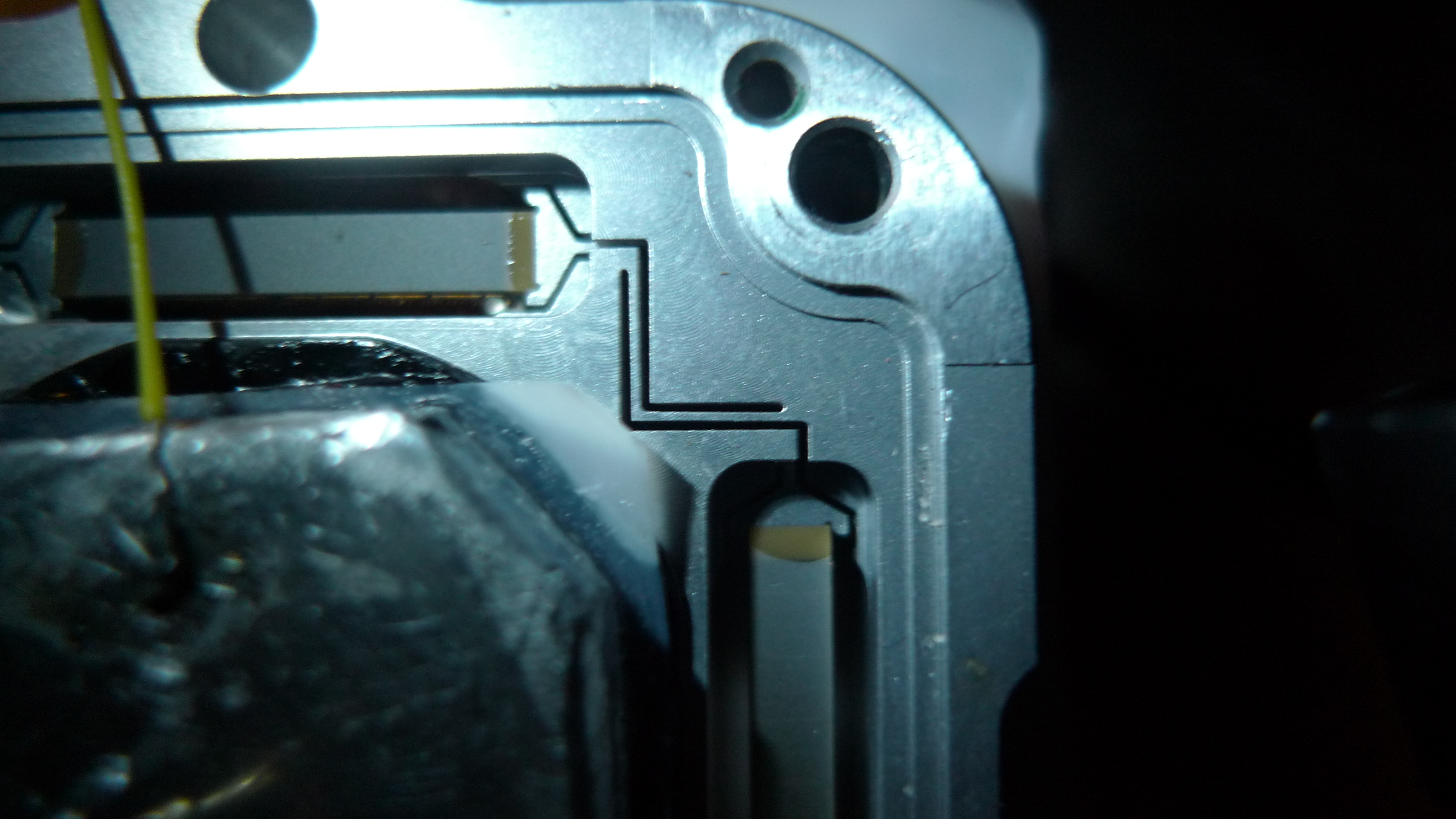
I picked some of these Piezo stages up on eBay. They appear to be an OEM design with ~15 microns of travel and I believe a 150v drive voltage. They’re obviously designed for some kind of optics application.
Here’s a video of it in action with the covers removed. The calipers are set at 0.5mm. I’m using a 0 to 150v square wave to drive the Y axis at 4Hz.
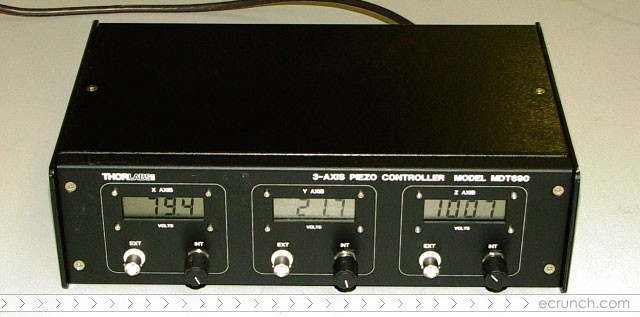
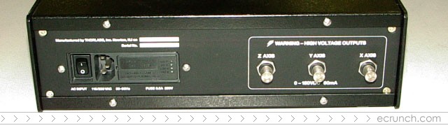
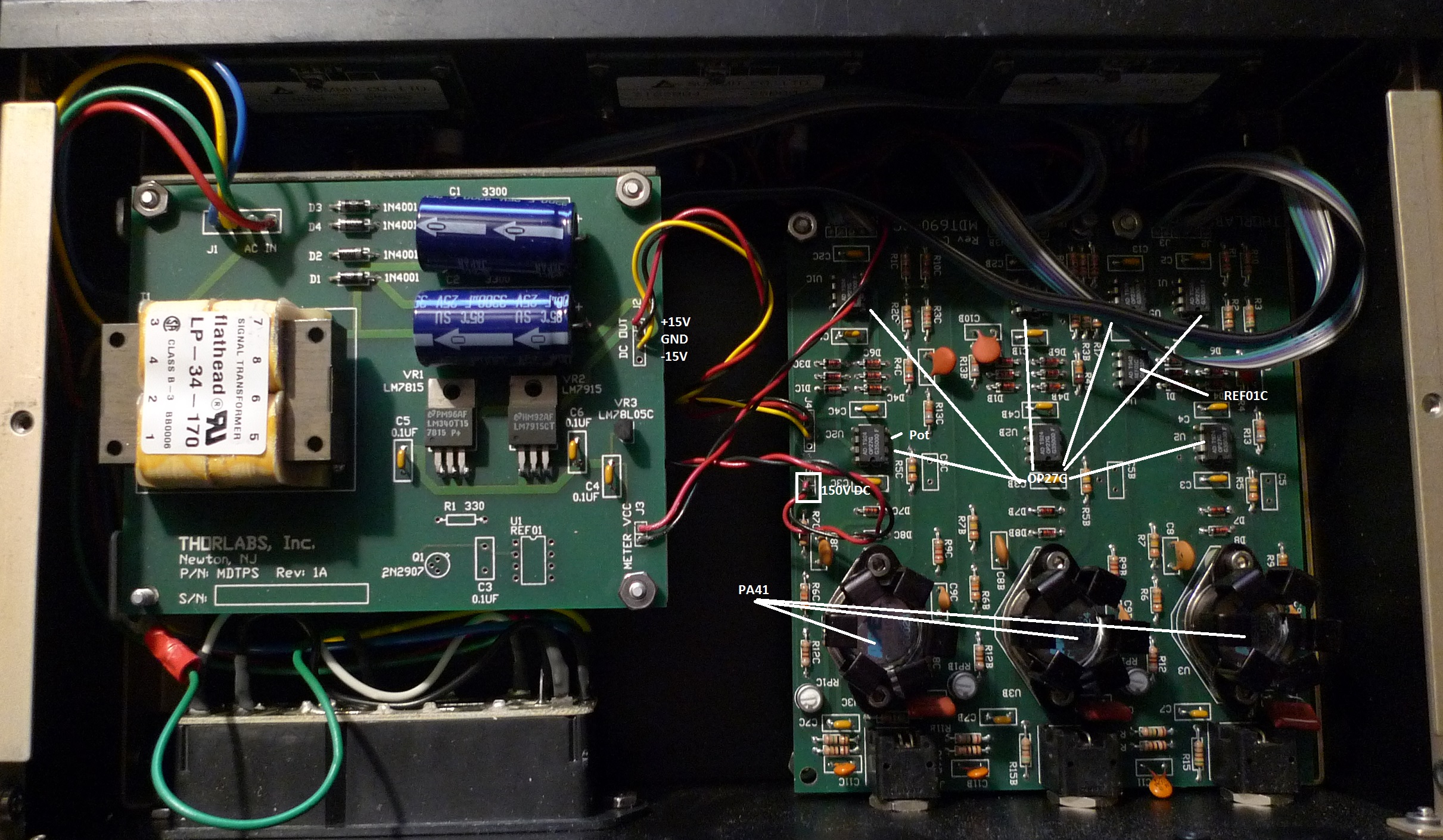
The MDT690 is a 3 axis piezo. In simple terms it takes a 10V input and generates a 150V output to drive a piezo electric actuator. Diagrams below show the devices internals. The first two pictures show the
Upper Boards
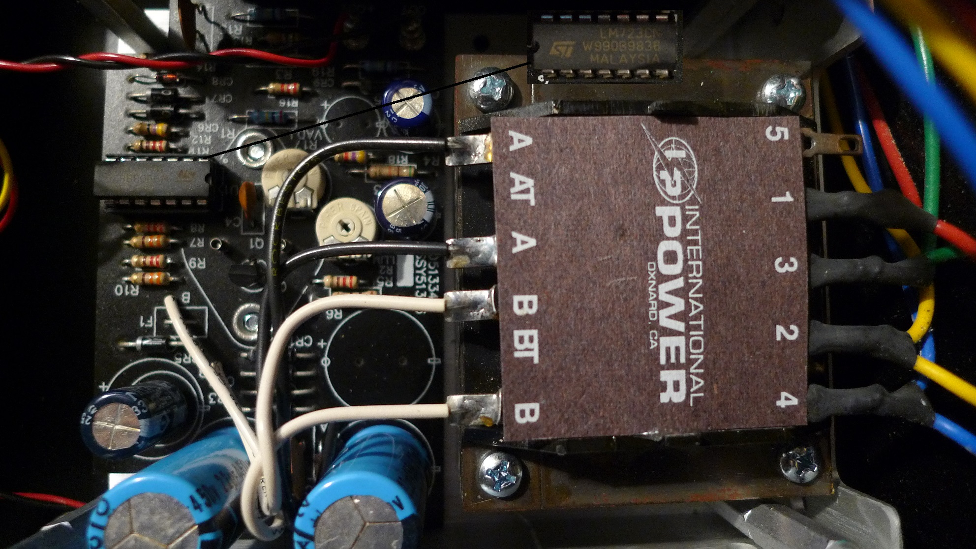
Lower Board
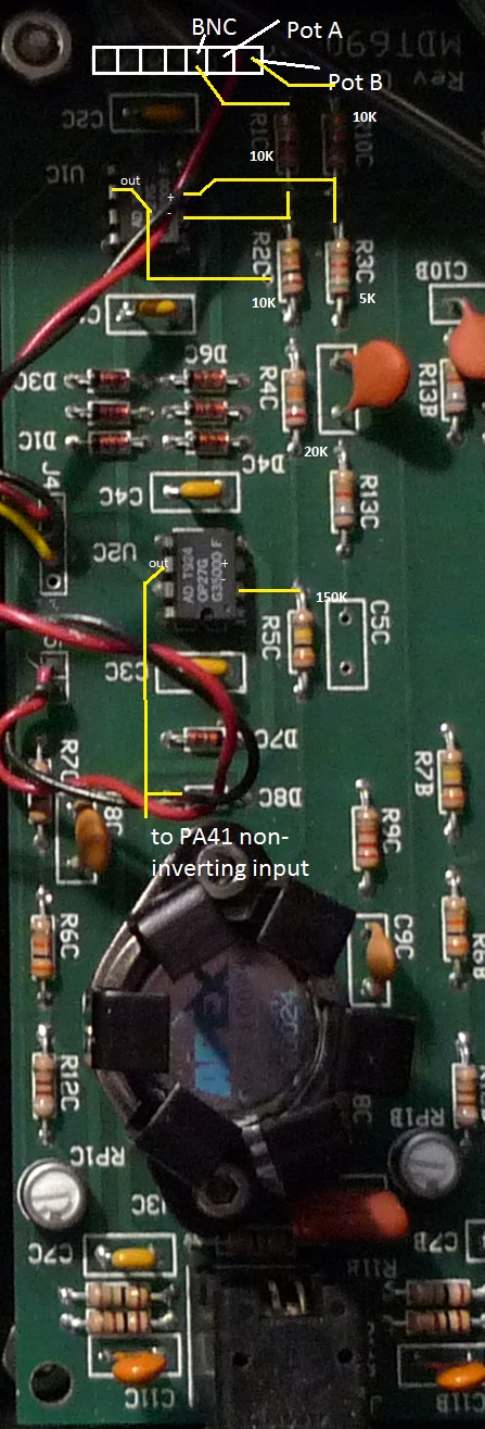
Single Channel Circuit
Each channel uses two OP27s and an PA41. The signal from the offset pot and the BNC on the front panel are combined and head into the first OP27 which appears to be in an inverting configuration. This heads into a second OP27, I didn’t traceout the feedback on this but assume it’s a buffer for the PA41 and either it or the PA41 re-invert the signal. Comments welcome!
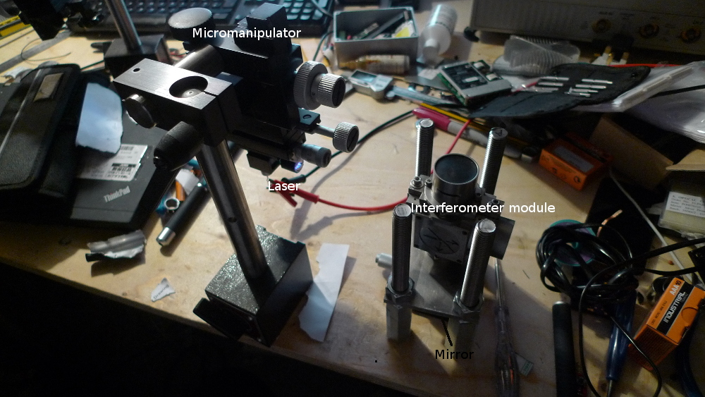
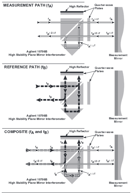
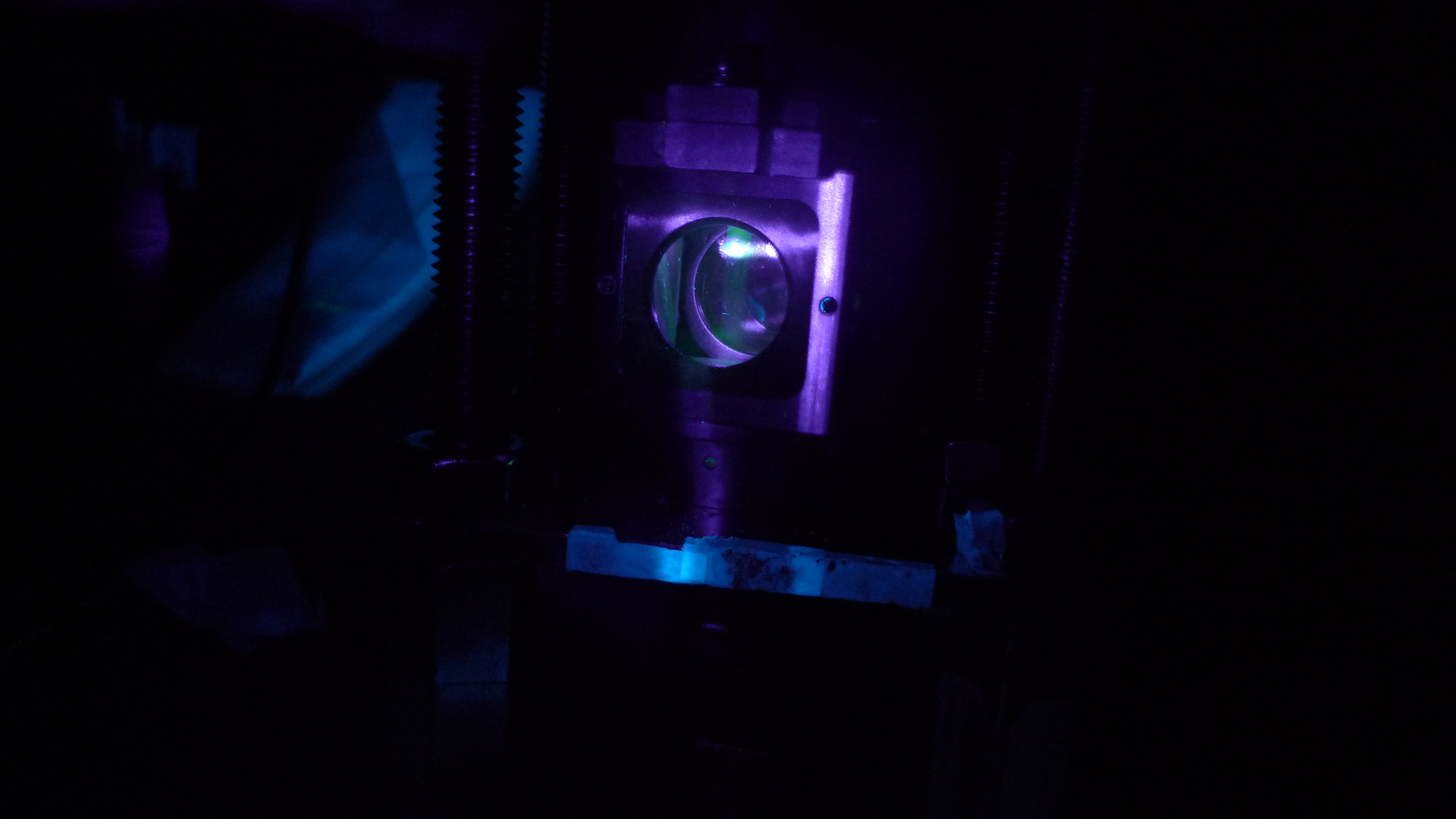
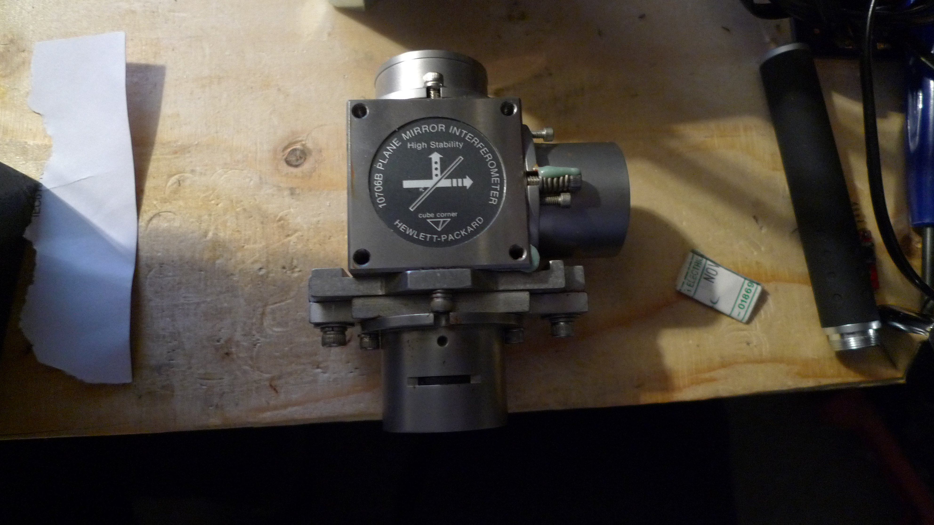
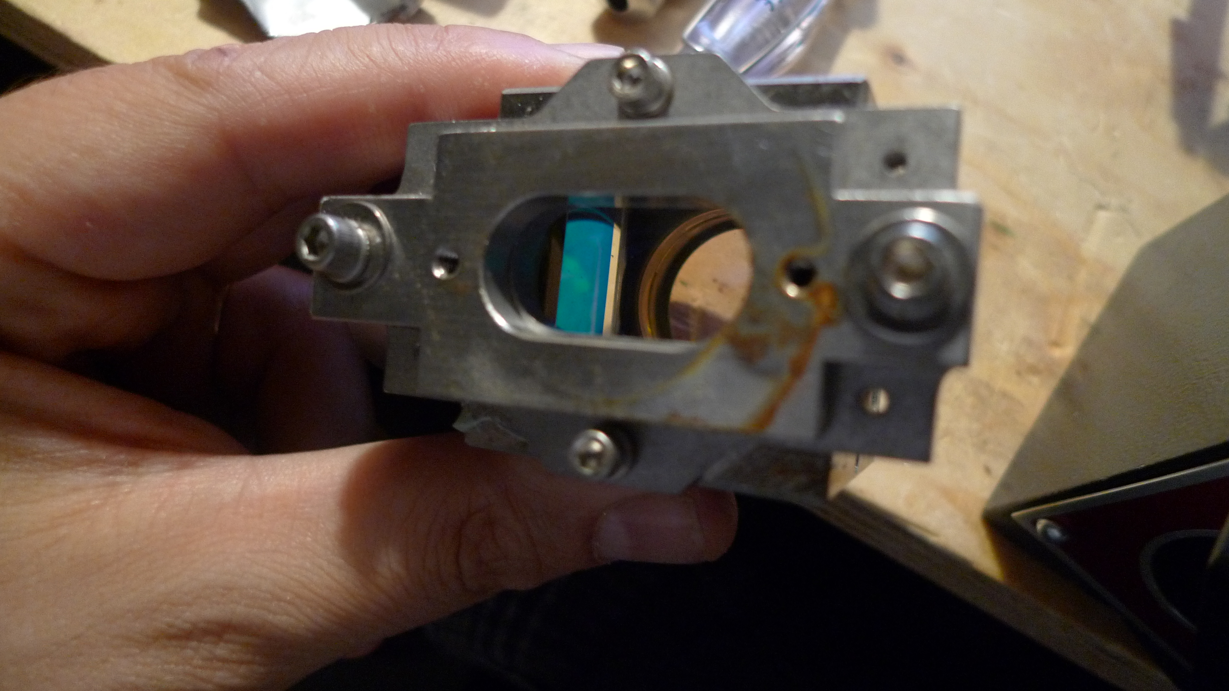
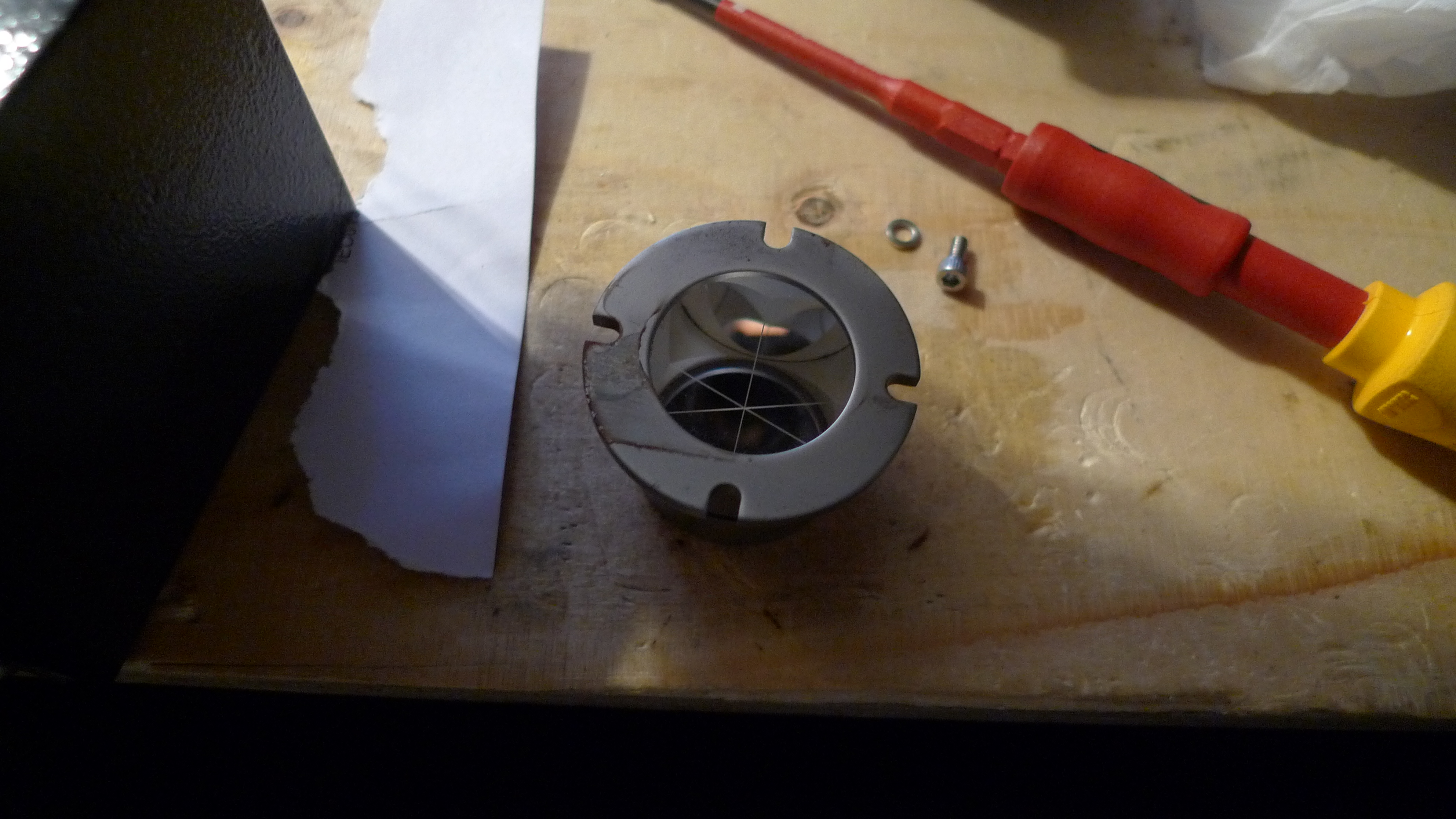
I picked up a HP 10706B interferometer module. The 10706B is a michelson interferometer. Michelson interferometers use the interference between a reference and measurement beam in order to measure distances of a few hundred nanometers.
The image below from the HP docs shows the path of the reference and measurement beams:
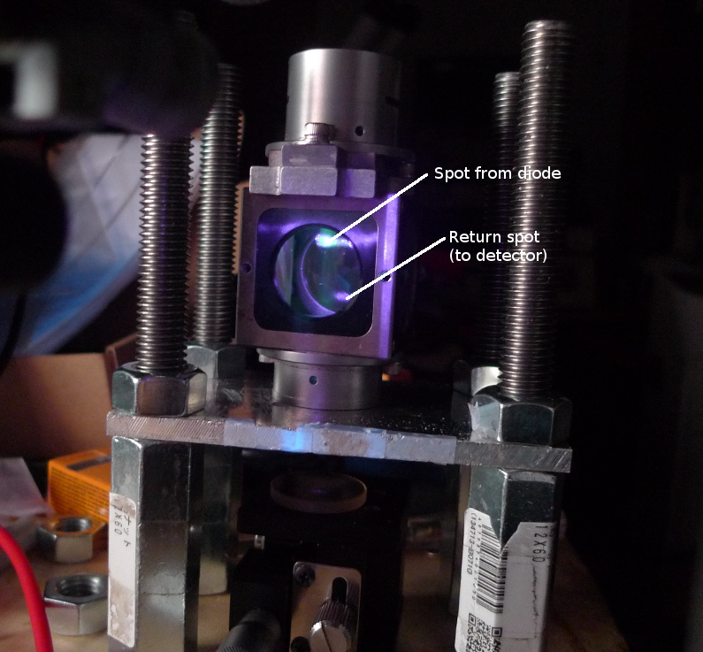
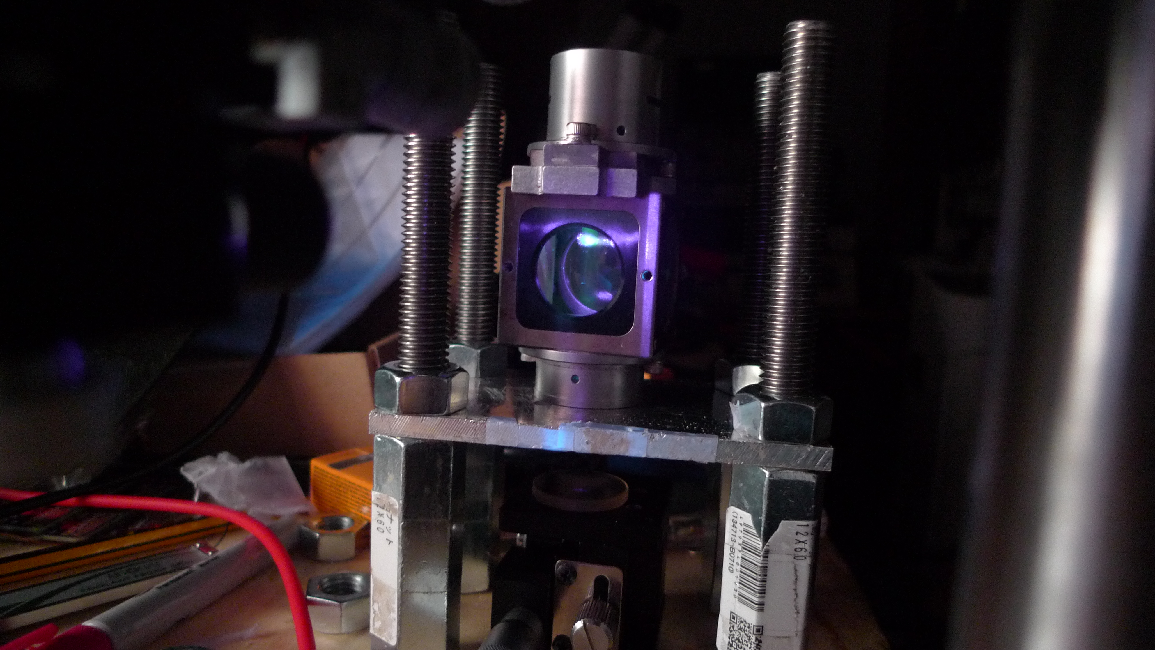
Anyway, I started playing around with it. Initially just to understand the beam path and see if I could see the beam reflected off the measurement mirror. I setup the laser and interferometer as shown above and could see the reflected beam. As expected the reflected beam dimmed when I occluded the mirror.
In this configuration it’s very unlikely that I’d be able to see the reference and measurement beams interfering. So I’ll be trying everything out on the anti-vibration table next.
My name is Nava Whiteford. I’ve worked for a few sequencing companies. I have equity in a few sequencing companies based on my previous employment (I try to be unbiased in my posts). You can contact me at: [email protected]