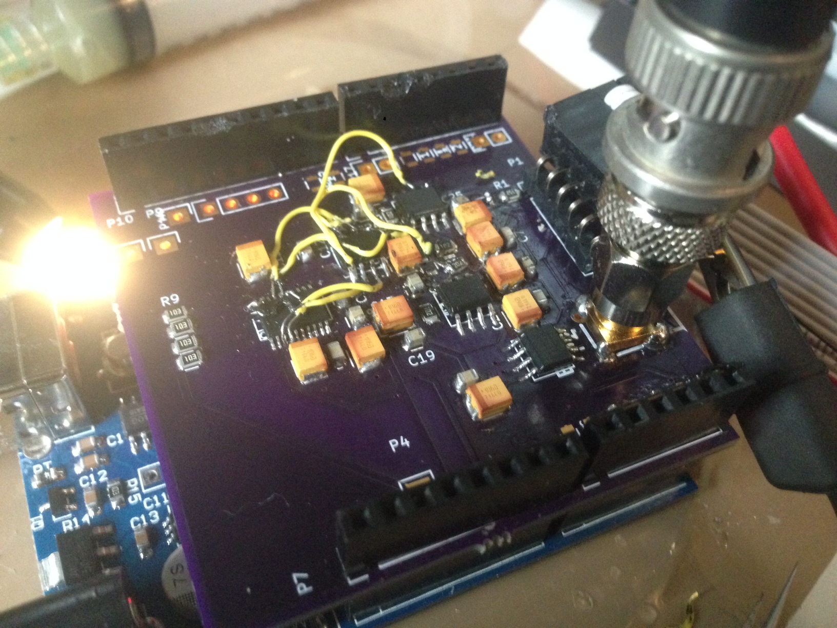
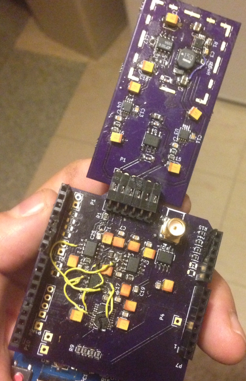
Tried to tidy up the patches a bit and fix the gain issue previously noted appears to have been a config error (wasn’t configured correctly for the external unity gain opamp). Test code follows:
#include <SPI.h>

const int reset = A5;
const int clr   = A4;
const int ldac  = A3;
const int sync  = A2;

#define AD5791_NOP 0 // No operation (NOP).
#define AD5791_REG_DAC 1 // DAC register.
#define AD5791_REG_CTRL 2 // Control register.
#define AD5791_REG_CLR_CODE 3 // Clearcode register.
#define AD5791_CMD_WR_SOFT_CTRL 4 // Software control register(Write only).

typedef enum {
ID_AD5760,
ID_AD5780,
ID_AD5781,
ID_AD5790,
ID_AD5791,
} AD5791_type;

struct ad5791_chip_info {
unsigned int resolution;
};
static const struct ad5791_chip_info ad5791_chip_info[] = {
[ID_AD5760] = {
.resolution = 16,
},
[ID_AD5780] = {
.resolution = 18,
},
[ID_AD5781] = {
.resolution = 18,
},
[ID_AD5790] = {
.resolution = 20,
},
[ID_AD5791] = {
.resolution = 20,
}
};

AD5791_type act_device;

/* Maximum resolution */
#define MAX_RESOLUTION 20
/* Register Map */
#define AD5791_NOP 0 // No operation (NOP).
#define AD5791_REG_DAC 1 // DAC register.
#define AD5791_REG_CTRL 2 // Control register.
#define AD5791_REG_CLR_CODE 3 // Clearcode register.
#define AD5791_CMD_WR_SOFT_CTRL 4 // Software control register(Write only).
/* Input Shift Register bit definition. */
#define AD5791_READ (1ul << 23)
#define AD5791_WRITE (0ul << 23)
#define AD5791_ADDR_REG(x) (((unsigned long)(x) & 0x7) << 20)
/* Control Register bit Definition */
#define AD5791_CTRL_LINCOMP(x) (((x) & 0xF) << 6) // Linearity error compensation.
#define AD5791_CTRL_SDODIS (1 << 5) // SDO pin enable/disable control.
#define AD5791_CTRL_BIN2SC (1 << 4) // DAC register coding selection.
#define AD5791_CTRL_DACTRI (1 << 3) // DAC tristate control.
#define AD5791_CTRL_OPGND (1 << 2) // Output ground clamp control.
#define AD5791_CTRL_RBUF (1 << 1) // Output amplifier configuration control.
/* Software Control Register bit definition */
#define AD5791_SOFT_CTRL_RESET (1 << 2) // RESET function.
#define AD5791_SOFT_CTRL_CLR (1 << 1) // CLR function.
#define AD5791_SOFT_CTRL_LDAC (1 << 0) // LDAC function.
/* DAC OUTPUT STATES */
#define AD5791_OUT_NORMAL 0x0
#define AD5791_OUT_CLAMPED_6K 0x1
#define AD5791_OUT_TRISTATE 0x2

void setup() {
  Serial.begin(115200);

  SPI.begin();

  pinMode(11,OUTPUT);
  digitalWrite(11,LOW);

  pinMode(reset, OUTPUT);
  pinMode(clr  , OUTPUT);
  pinMode(ldac , OUTPUT);
  pinMode(sync , OUTPUT);

  // setup
  digitalWrite(ldac,HIGH);
  digitalWrite(reset,HIGH);
  digitalWrite(clr,HIGH);
  digitalWrite(sync,HIGH);
  SPI.beginTransaction(SPISettings(20000000, MSBFIRST, SPI_MODE1));

  long status = AD5791_GetRegisterValue(AD5791_REG_CTRL);

  status = AD5791_GetRegisterValue(AD5791_REG_CTRL);

  Serial.print(status,BIN);
  Serial.println();

  digitalWrite(ldac,LOW);
  status = AD5791_SetRegisterValue(AD5791_REG_DAC, 1);
  digitalWrite(ldac,HIGH);


  unsigned long oldCtrl = status;
  oldCtrl = oldCtrl & ~(AD5791_CTRL_LINCOMP(-1) | AD5791_CTRL_SDODIS | AD5791_CTRL_BIN2SC | AD5791_CTRL_OPGND);

  oldCtrl = oldCtrl | AD5791_CTRL_RBUF;
  status = AD5791_SetRegisterValue(AD5791_REG_CTRL, oldCtrl);

  status = AD5791_GetRegisterValue(AD5791_REG_CTRL);


  Serial.print(status,BIN);
  Serial.println();
  Serial.println("DAC");

  digitalWrite(ldac,LOW);
  status = AD5791_SetRegisterValue(AD5791_REG_DAC, 1);
  digitalWrite(ldac,HIGH);

}


long AD5791_SetRegisterValue(unsigned char registerAddress, unsigned long registerValue) {
  unsigned char writeCommand[3] = {0, 0, 0};
  unsigned long spiWord = 0;
  char status = 0;
  spiWord = AD5791_WRITE | AD5791_ADDR_REG(registerAddress) | (registerValue & 0xFFFFF);
  writeCommand[0] = (spiWord >> 16) & 0x0000FF;
  writeCommand[1] = (spiWord >> 8 ) & 0x0000FF;
  writeCommand[2] = (spiWord >> 0 ) & 0x0000FF;

  digitalWrite(sync,LOW);
  status = SPI.transfer(writeCommand[0]);
  status = SPI.transfer(writeCommand[1]);
  status = SPI.transfer(writeCommand[2]);
  digitalWrite(sync,HIGH);

  return 0;
}

long AD5791_GetRegisterValue(unsigned char registerAddress) {
  unsigned char registerWord[3] = {0, 0, 0};
  unsigned long dataRead = 0x0;
  char status = 0;
  registerWord[0] = (AD5791_READ | AD5791_ADDR_REG(registerAddress)) >> 16;

  digitalWrite(sync,LOW);

  status = SPI.transfer(registerWord[0]);
  status = SPI.transfer(registerWord[1]);
  status = SPI.transfer(registerWord[2]);
  digitalWrite(sync,HIGH);


  registerWord[0] = 0x00;
  registerWord[1] = 0x00;
  registerWord[2] = 0x00;
    digitalWrite(sync,LOW);
  registerWord[0] = SPI.transfer(0x00);
  registerWord[1] = SPI.transfer(0x00);
  registerWord[2] = SPI.transfer(0x00);
    digitalWrite(sync,HIGH);
  dataRead = ((long)registerWord[0] << 16) |
             ((long)registerWord[1] << 8) |
             ((long)registerWord[2] << 0);
  return dataRead;
}

long current_value=0;
long d=0;
void loop() {

    digitalWrite(ldac,LOW);
    int status = AD5791_SetRegisterValue(AD5791_REG_DAC, current_value);
    digitalWrite(ldac,HIGH);
   // Serial.print(current_value);
   // Serial.print("\r\n");

  current_value+=10000;
if(current_value>524000) current_value=-524000;
}
 RSS
RSS