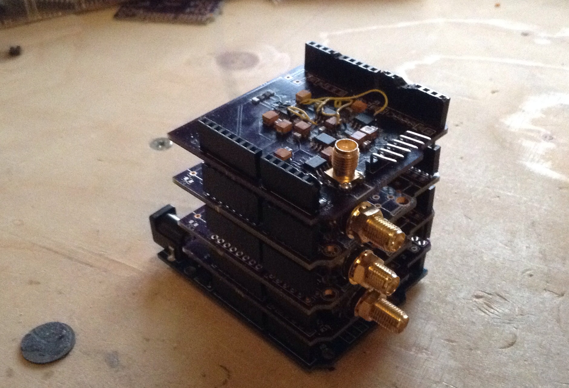
Regulator Board
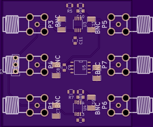
Board layout with the regulators and 5V reference from the previous design for noise testing.
+/- 13V Powerboard Rev2
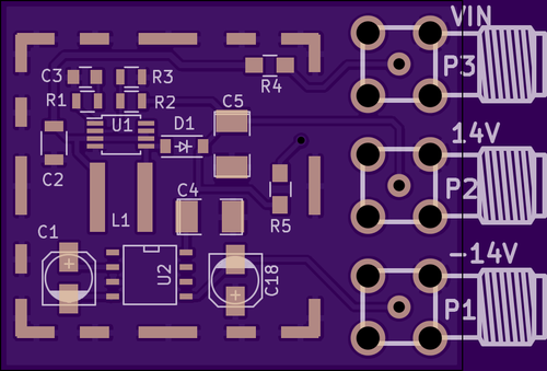
After bring up the previous version of the power board I decided to make some revisions. In addition to the changes mentioned in my previous post, I decided to break the regulator and reference out on to separate boards. My hope is that this allows me to add filtering between the boards and experiment with supply types. The board now also uses SMA connectors…
Couldn’t remount RDWR because of unprocessed orphan inode list. Please umount/remount instead
My Debian laptop rootfs decided to go readonly this evening. The usual solutions are to either fsck the drive or remount readwrite. Unfortunately the usual solutions didn’t work this time. These are my notes on fixing the issue, any mostly for my own reference and to document the pain and suffering involved…
First of all it seems that my system didn’t have fsck.ext4 installed, and of course I couldn’t install it as the system was readonly. In anycase, as I’m using the root FS I wouldn’t have been able to run it anyway…
So I attempted to remount rw using “mount / -o remount,rw” as usual but was presented with the following error:
“Couldn’t remount RDWR because of unprocessed orphan inode list. Please umount/remount instead”
So… what next. Well after much fumbling I decided to see if I could create a new FS and boot to that, install fsck.ext4 and clear the errors. Of course my system also lacked mkfs.ext4… So I figured maybe I could create a new root file system in a ram disc install mkfs.ext4 on that and then setup the new partition.
I created a tmpfs (ram disc) using “mount tmpfs ./mnt -t tmpfs -o size=2048mb”. Then used:
mkdir sbin;mount --bind /usr /mnt/sbin
mkdir bin;mount --bind /bin /mnt/bin
mkdir usr;mount --bind /usr /mnt/usr
mkdir lib;mount --bind /usr /mnt/lib
mkdir lib64;mount --bind /lib64 /mnt/lib64
mkdir proc;mount --bind /proc /mnt/proc
mkdir run;mount --bind /run /mnt/run
To bind the various static user files. I copied etc manually. var was not copied, but I copied files into var as required. Make sure the swap is turned off (swapoff -a)
Next it chrooted into this tmpfs (chroot ./mnt). apt-get update (faff around adding missing files/directories to /var). Then, apt-get install e2fsprogs. This fails as too much of the tree is still readonly. Anyway… dig out the dpkg (find / -name e2fsprogs*). And extract it… (mkdir e;dpkg -x e2fsprogs_1.42.12-1.1_amd64.deb e).
Then find mkfs.ext4 in the extracted files… and make the new fs (mkfs.ext4 /dev/sda5 (or whereever your swap was)) .
Then mount and copy all the important parts of your system across:
mkdir m
mount /dev/sda5 m
cp -r /etc m
cp -r /lib m
cp -r /lib64 m
cp -r /e m
cp -r /bin m
cp -r /sbin m
cp -r /boot m
...
Reboot… struggle with grub changing the boot parameters (e for edit, then change hd0,msdos1 to hd0,msdos5) until the system boot to the new drive.
Find out that it crashes into the initrd. mount the new partition. chroot to the new partition. Run fsck.ext4 /dev/sda1. Hit Y a bunch. Reboot. Sleep.
 RSS
RSS