March 19, 2018, 2:51 am
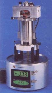 Some time ago I picked up a Veeco/Bruker AFM on eBay. The lot only contained the probe microscope itself (similar to that shown to the left). So, the control unit (a 2U box to electronics which contains among other things the high voltage drivers for the Piezo tube etc) was missing. One of the connectors was also damaged (unusable). They use fancy expensive connectors so replacing this one connector would cost about 100USD (the whole used unit was 400USD). For reference a complete new system is somewhere in the region of 200,000USD…
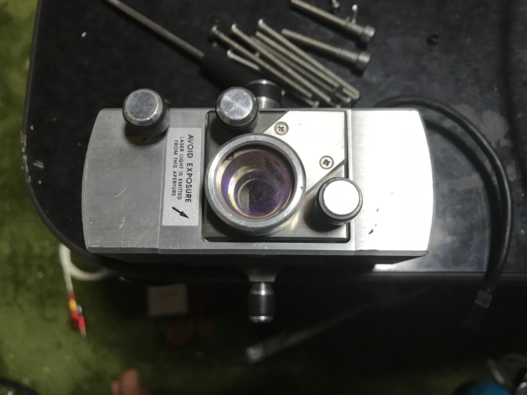
Anyway… I was pulling it apart recently and wanted to post some internal pics of the unit. These instruments are actually pretty simple (though I’ve not pulled apart the optical part just which I think is mostly just a quadrant photodiode…).
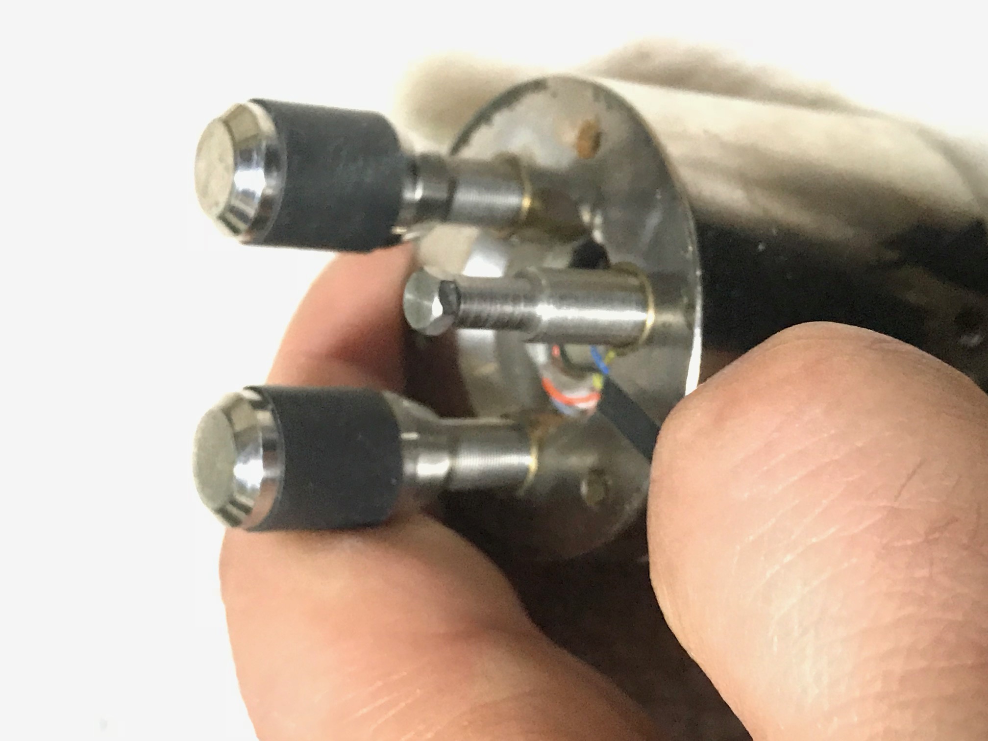
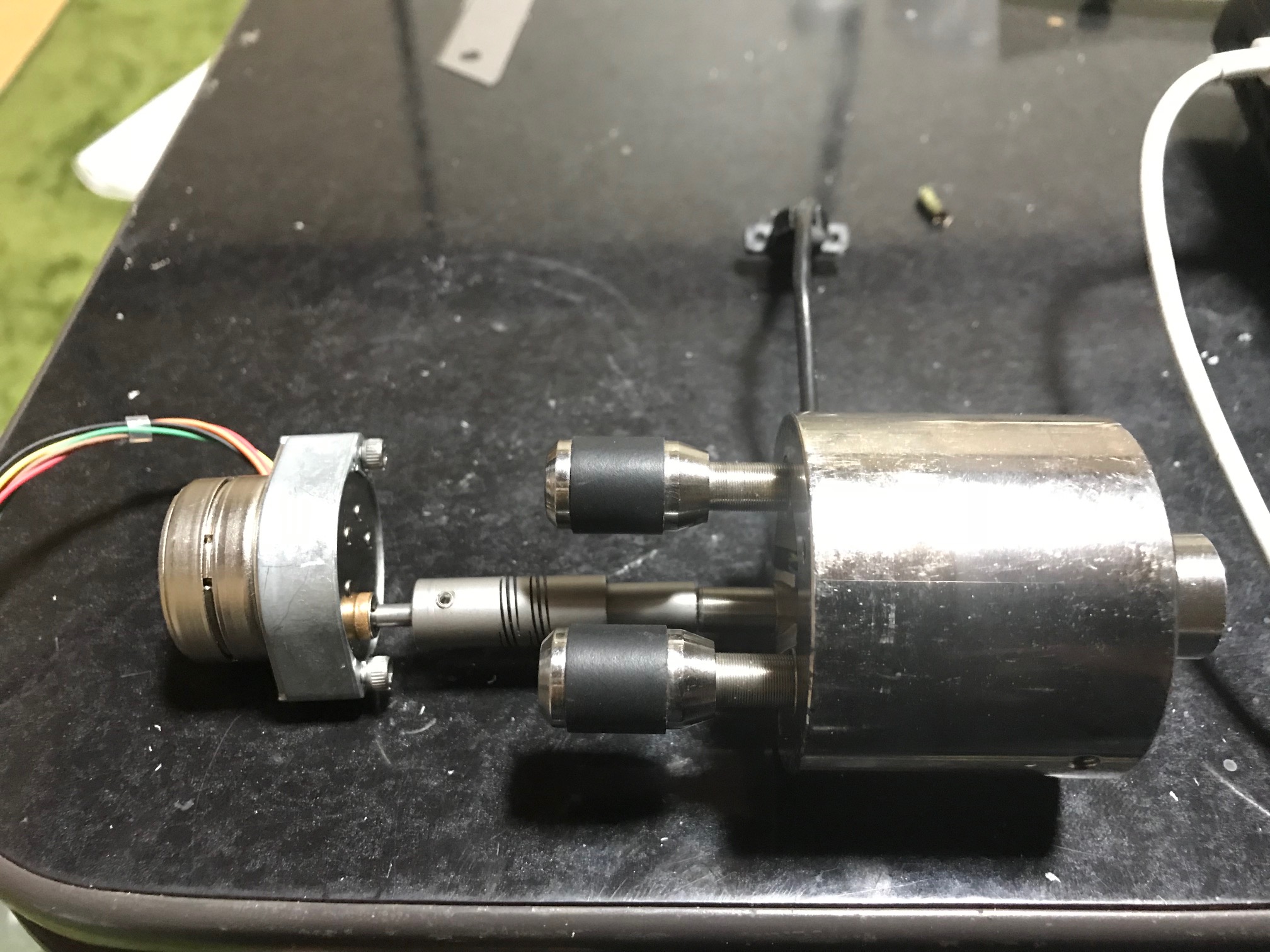
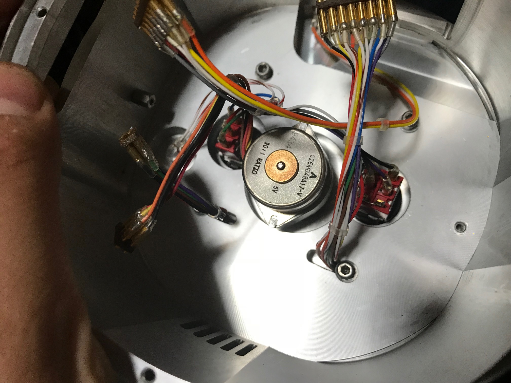
Mostly I was interested in how they do the coarse approach, here’s a picture of the complete coarse approach system extracted from the AFM:
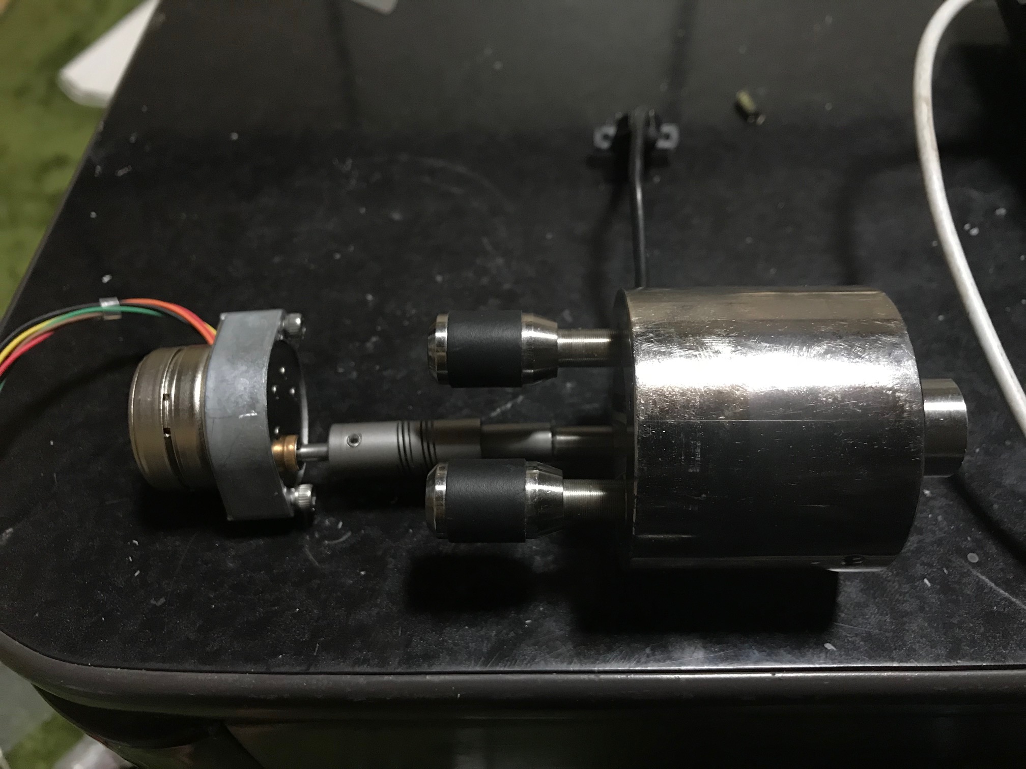
The coarse approach uses a Portescap 30:1 geared stepper motor. This appears to be nothing particularly special, though it’s pretty low profile. That’s connected to a coupler. The coupler itself is kind of interesting. It connects the motor (using grub screws) to a adjuster on the Piezo head/stage. The connection to the stage does not use grub screws. This uses a hex/allen type head which just sits loosely in the coupler. I think this means that when the stepper is not engaged there’s less mechanical coupling between these parts. This possibly helps with vibration isolation. I found it interesting anyway, and I’d be curious to know where you can buy these kinds of couples (and the adjuster which the hex end). The adjuster looks to be something like 100TPI, though I didn’t measure it exactly.

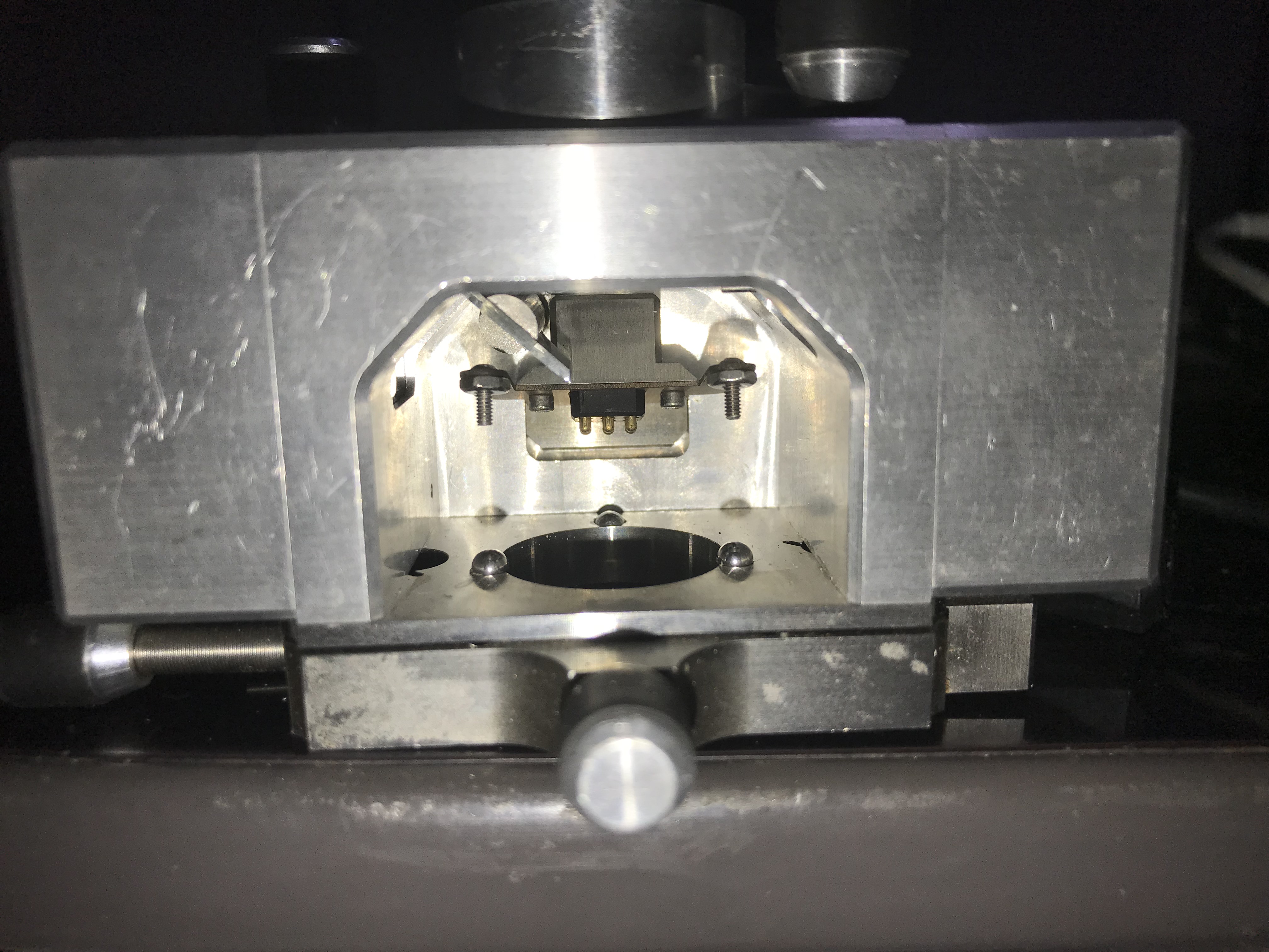
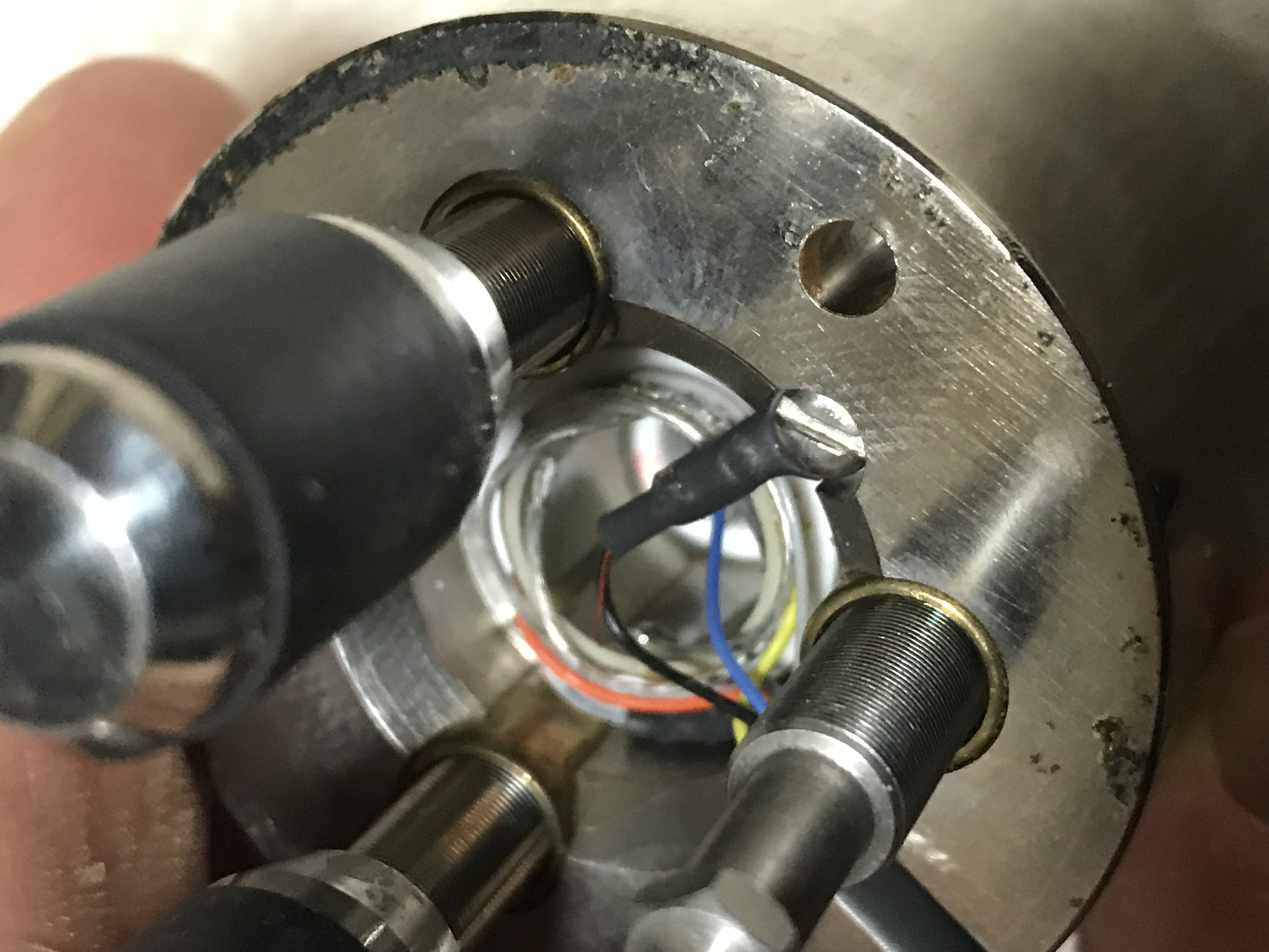 The head itself, looks very hand made. You can see the piezotube and the solder connections to this without disassembling the unit. For the coarse approach, there are 3 adjusters. The one that is driver by the stepper (shown above) and two others hand driven (with knobs on) when setting up the instrument you’re supposed to do some manual adjustment before starting the approach to get the head kind of close (and the orientation right).
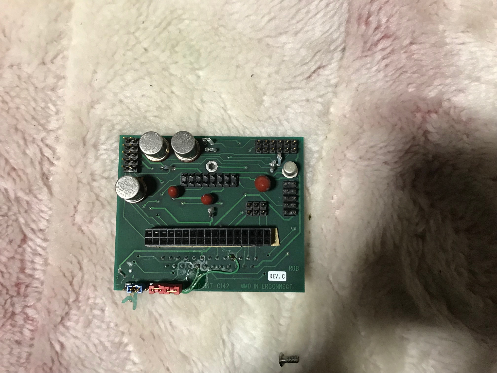
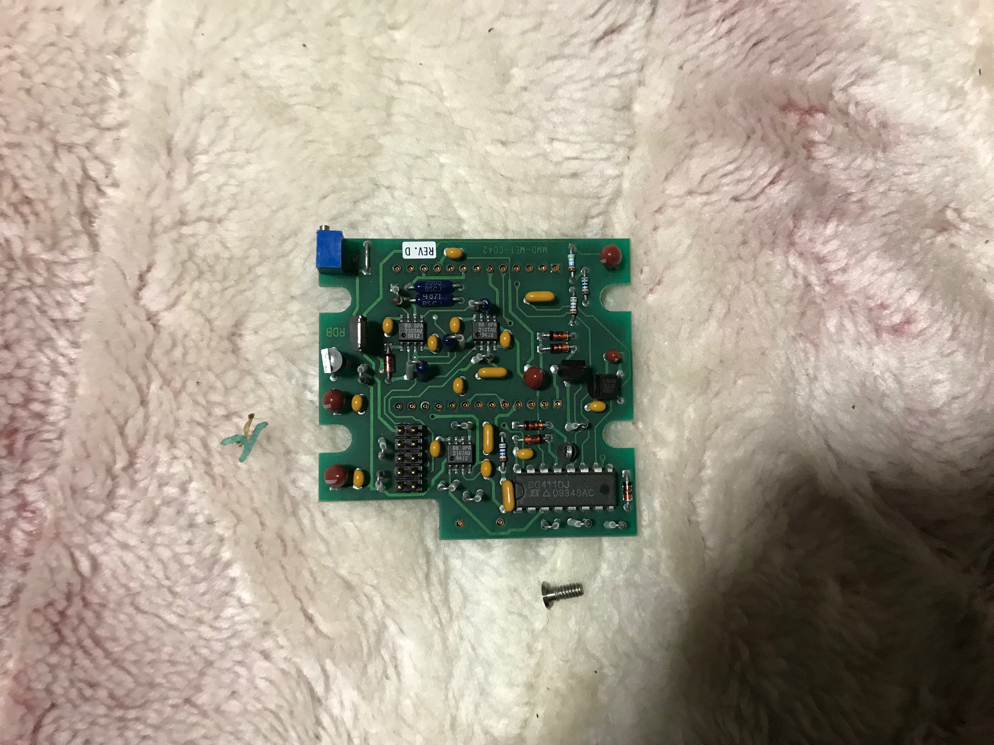
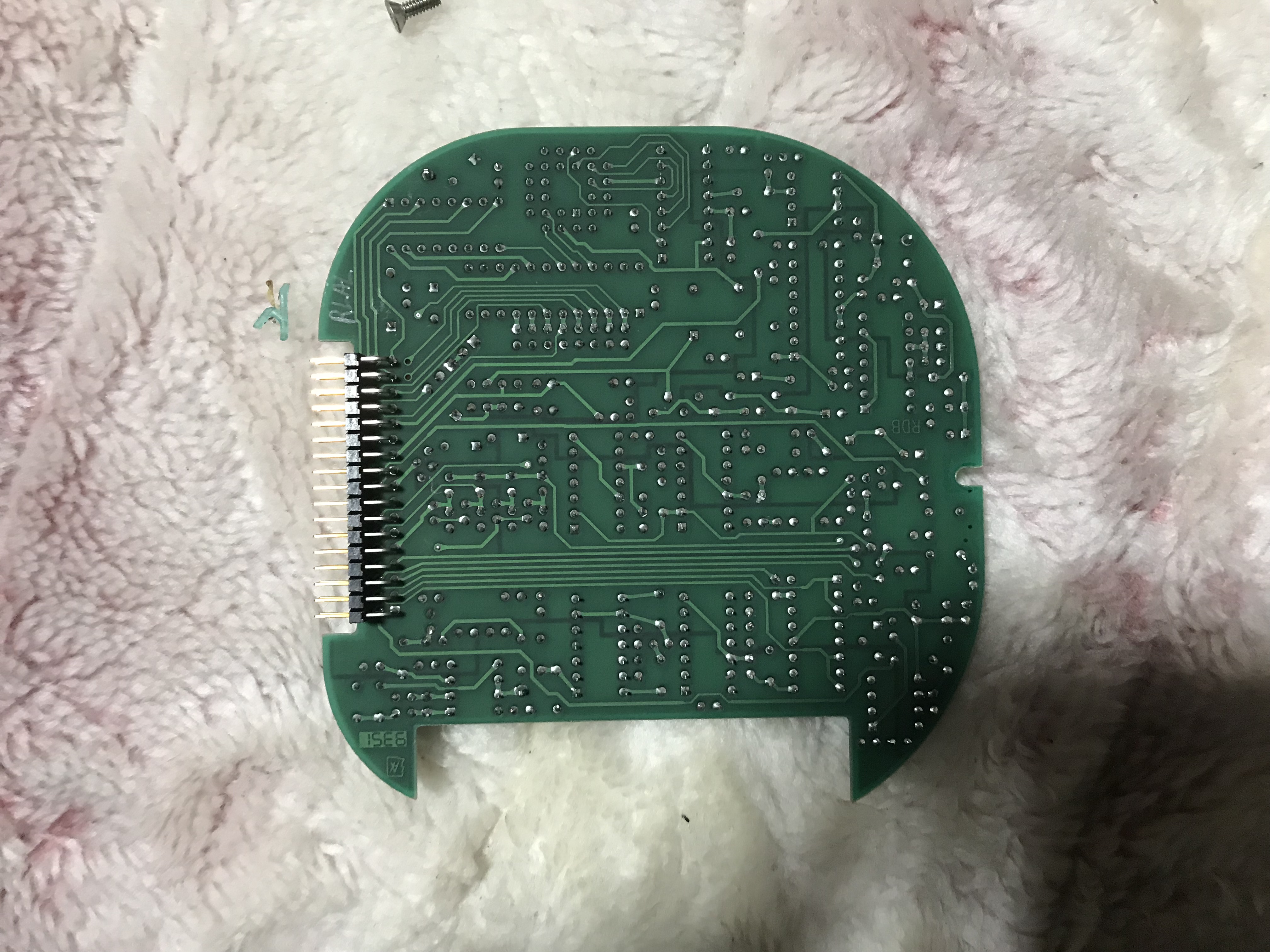
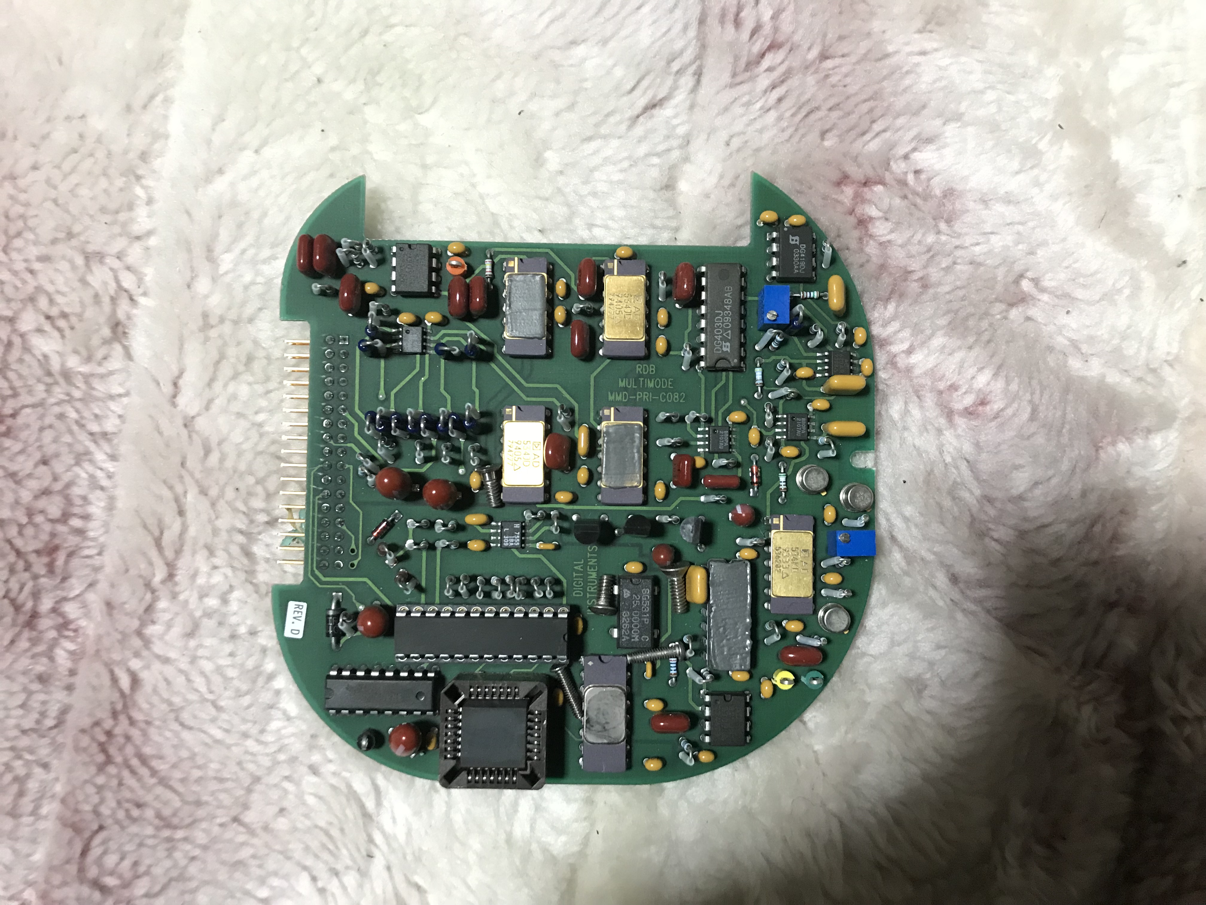
I’ve not looked closely at the rest of the electronics in the unit. I’d guess there’s nothing super interesting going on. It didn’t look like any of the high voltage drive electronics was present (the Piezo tube needs ~100V drive voltage).
Anyway… a bunch more pictures follow for reference:


April 4, 2017, 7:20 pm
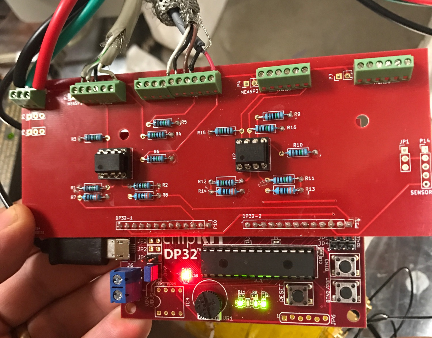
I’ve put together a simple interface for use with Sam’s and Jan’s HP Interferometer code for the ChipKIT 32. It’s really just a layout of the design listed on their site, however avoids some wire-wrapping. You can find the Kicad files and gerbers on github.
I decided to use all through-hole components to make it easy to assemble. In a future revision I might move to SMD, the mounting points need re-positioning. I’d also like to try laying out the PIC32 on the same board. The board however works well for me, and it depends if I get any interest in developing it further. If you’d like one let me know and I’ll put it in my shop.
The board I’ve designed routes power traces to terminal blocks to which the receiver and laser head are attached. This helps simplify wiring.
April 3, 2017, 5:28 pm
These are my notes on building Sam and Jan’s interferometer signal processing firmware for the Chipkit DP32.
First download the firmware, this is the version I used: http://www.repairfaq.org/sam/uMD1/uMD1_FW_v56.10.ino (local copy (gz)).
Then install UECIDE, download it here: http://uecide.org/download.php. I used the latest version on Linux (uecide-0.8.8alpha22-linux.zip).
Next in Tools->Plugin Manager select Boards->chipKIT->chipKIT DP32 and then select “install”… wait.
Next in Tools->Plugin Manager select Compilers->PIC32->PIC32 Compiler for MX version 4.5.2 and then select “install”… wait.
Make sure the plugins have actually installed. UECIDE fails silently if you run out of disk space…
Open the ino file above (File-Open) it’ll move it into a scratch area. Select Hardware->Boards->chipKIT->chipKIT DP32
Select Hardware->Compilers->pic32-tools-452
In a text editor open: .uecide/compilers/pic32-tools-452/pic32mx/include/plib.h, comment out line 61 (#include <peripheral/ports.h).
Hit compile, hope for the best.
Remove all the jumpers from the chipKIT 32 board. Reinstall one jumper on JP7 furthest from the terminal block, the position is labeled VBUS.
Plug the board into a USB port. Press Press RESET and PGM buttons at the same time. Release RESET then PGM.
In UECIDE select Hardware->Device and then whichever serial port the chipKIT 32 is connected to.
Select Hardware->Programmers->Upload to chipKIT board via avrdude.
Press “Program”. Hope for the best again.
If everything has worked correctly you should be able to see the chipKIT throwing out numbers in serial console. Seemly baudrate settings don’t matter.
February 28, 2017, 3:02 am
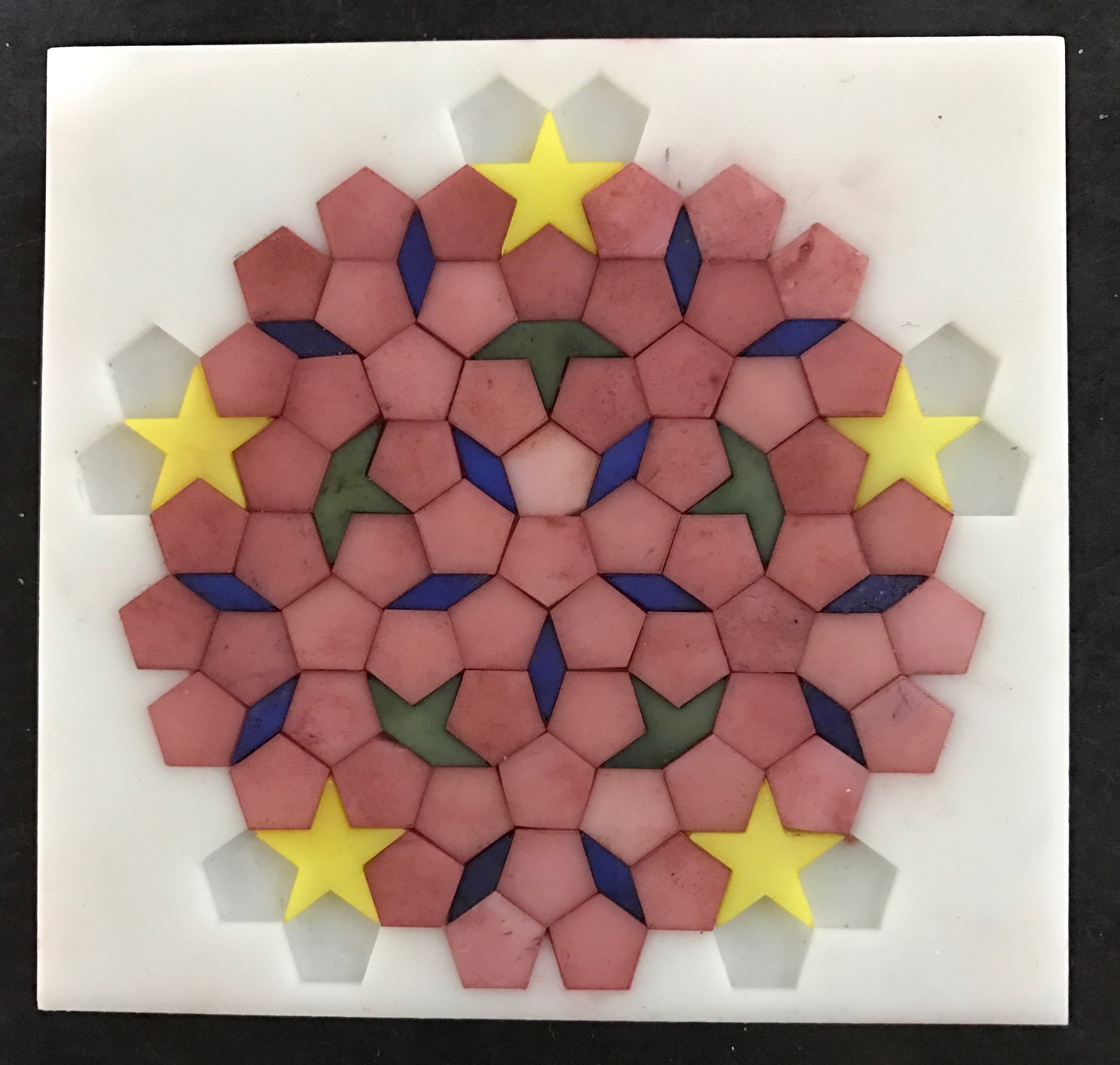
 I’ve been working on a small tile puzzle “thing” based on a penrose (aperiodic) tiling. I used the tiling on the wikipedia page for this first test run. I’m not sure if I’ll actually do another revision, but thought I should probably document what worked and what didn’t.
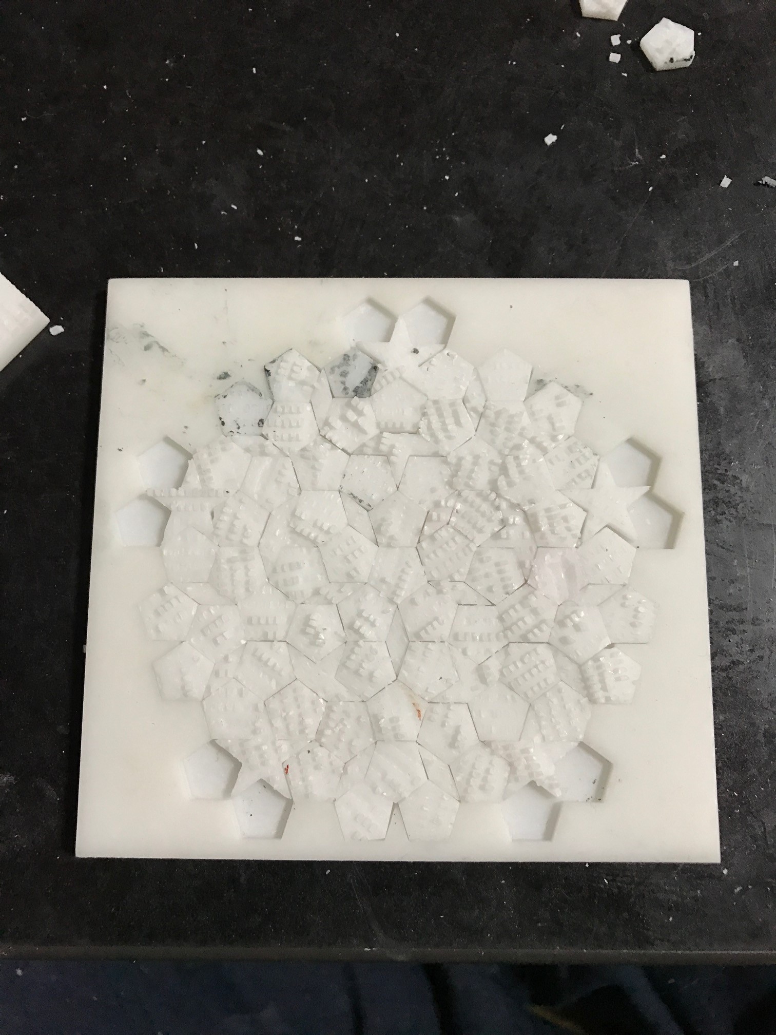
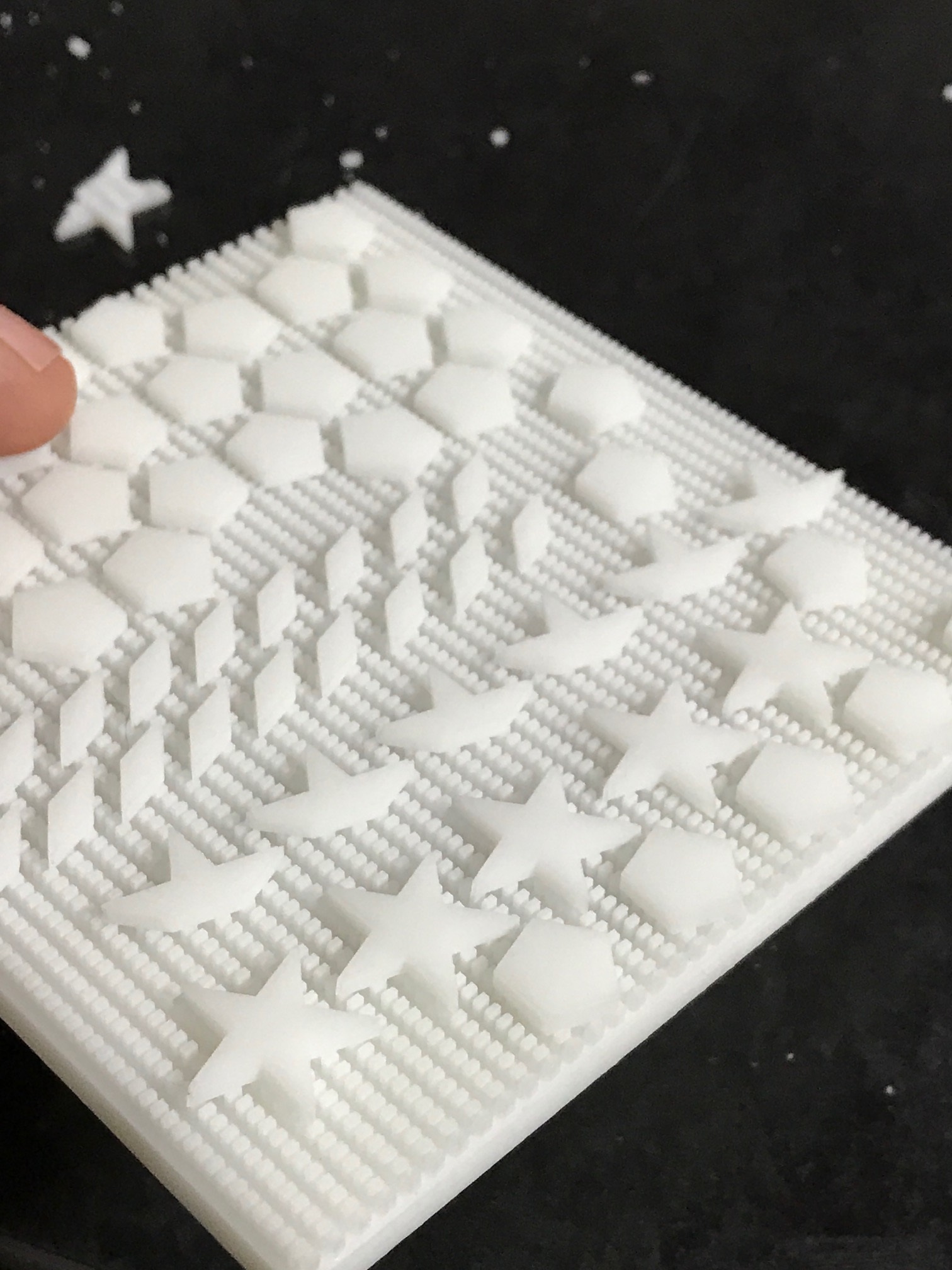
Firstly, I decided to fabricate the whole puzzle as a single part. The top of the part contains the frame into which the tiles sit. The tiles themselves are attached to the back of the frame and need to be sliced off. They are supported by a series of pillers 2x1mm in size and 2mm tall. I figured they would be easy to hack off. I was wrong, this was horribly difficult. I opted to fabricate the puzzle as one part because Itead (also most other SLA printing services) charge a fixed fee per part. As there are so many parts, creating each tile separately would be very expensive (probably 100 to 200USD in total).
I should most likely use either fewer, or different pillars to support the parts, or try a different strategy. Perhaps laser cutting this model would also be a better option.
There were a couple of thing that worked out well with the pillars though. I was surprised that they all fabricated correctly. No pillars were joined together under the parts. They didn’t cause any issues during printing, and it’s interesting to note that you can create complex void like this…
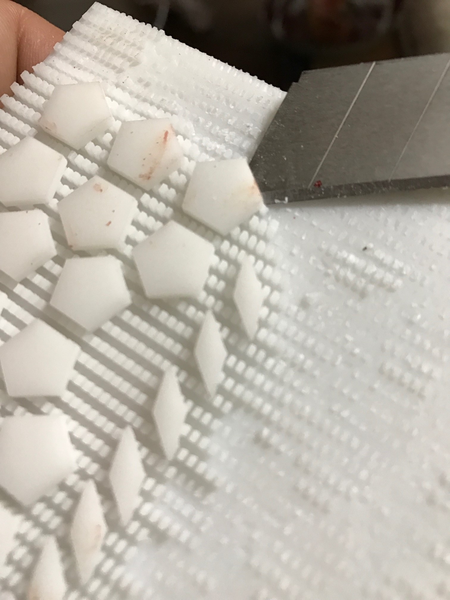 Hacking all the parts off took an age. The “stars” were also difficult to remove without breaking, but with some practice they could be removed relatively easily.
After removing the parts I did a fit test. As it turns out about 30% of the pentagons were the wrong size (about 1mm too big). Filing these down took a long, long time. I believe this is a design error on my part, the majority of parts had no issues. I was concerned that they might not fit in the frame as I’d given no tolerance in the design to allow for fabrication differences. The tiles were design to exactly fit in the frame with no extra space.
You can see in the fit test to the right that hunks of the pillars remained on the parts. Each part therefore needed to be filed down separately to get it flat. This also took much longer than I’d like and leaving me looking for better solutions.
Overall though, this was a reasonably successful experiment. I’ll be thinking about how to move forward, and if 3D printing is really the best option or if other methods might be better.