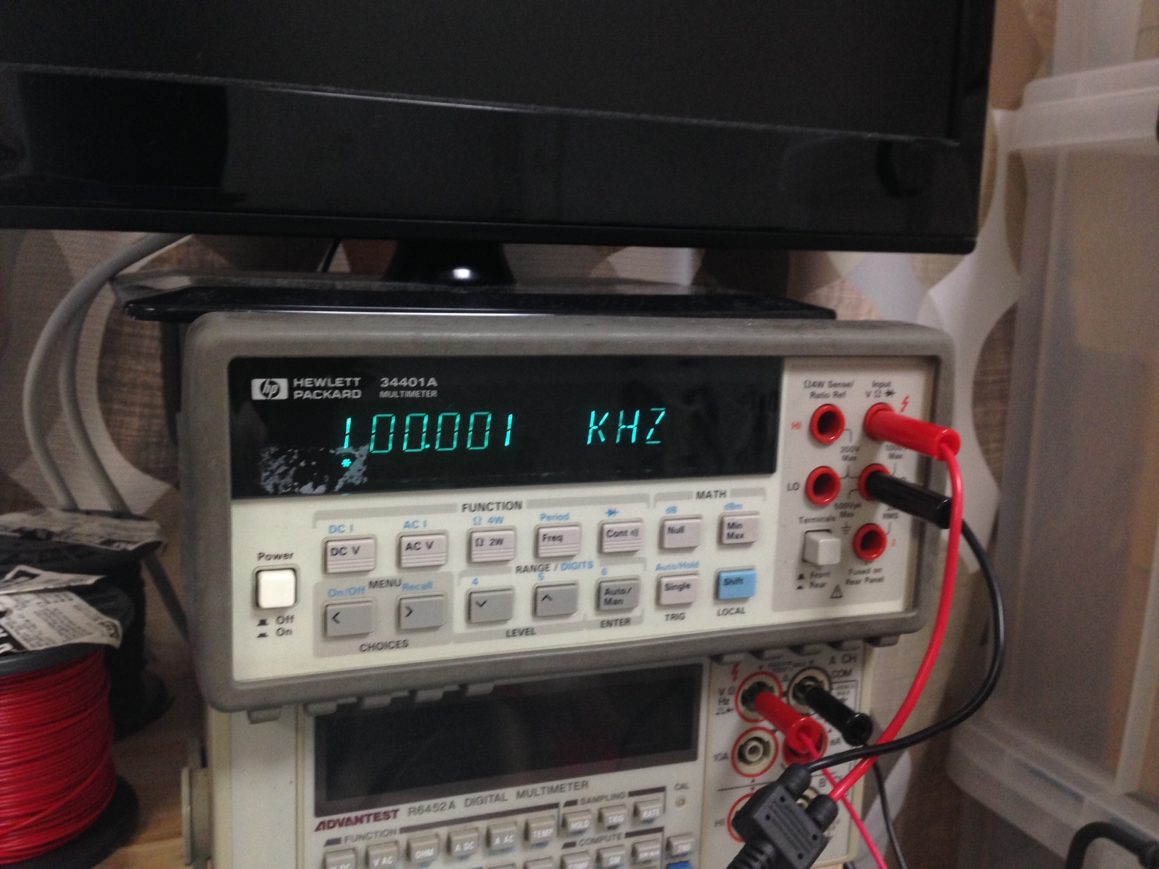
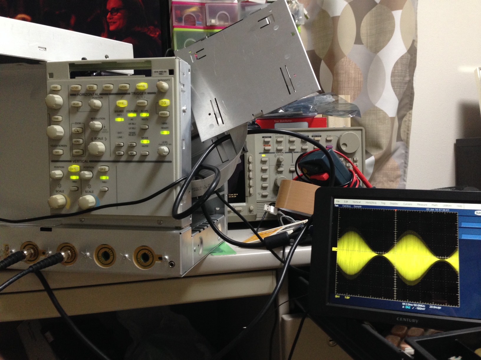
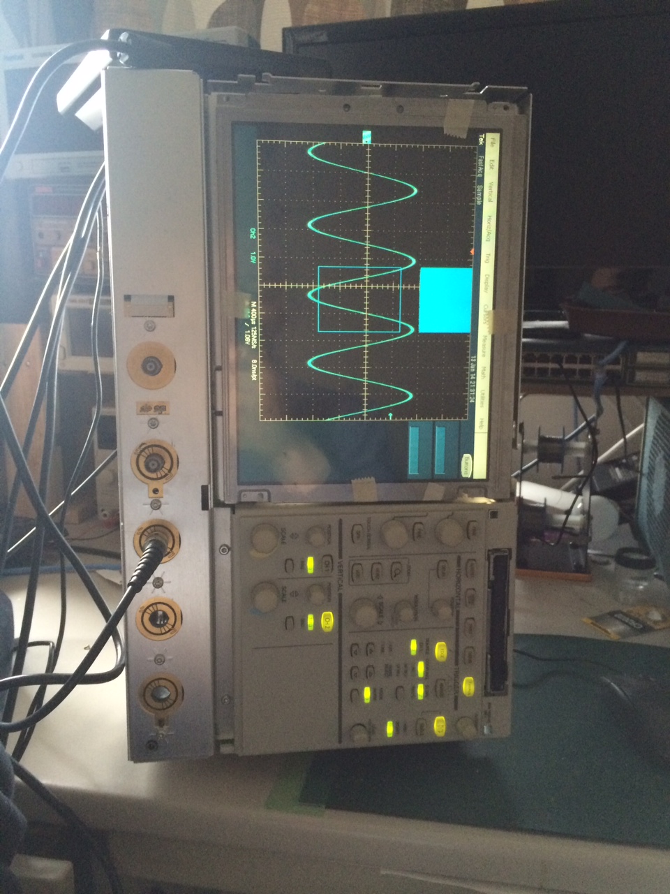
Tektronix TDS5052 repair

I picked up another broken Tektronix scope for about 200USD scope the other day. This one had no output on any on either VGA port or the integrated LCD. However the front panel LEDs did come up and it beeped on boot.

The TDS5000 series scopes follow a similar pattern to the TDS7000s with a x86 host and a PowerPC based system on the PCI bus. The layout however is a little more “normal” with the Power PC sitting in a PCI slot.

Once the BIOS was reset, I could get output on the integrated AGP graphics card of the Intel motherboard. I could even acquire snapshot measurements from both channels, a good sign that the acquisition hardware was working.

However still nothing on the Tektronixs PCI card which uses a Chips and Technologies 69000 graphics IC. In windows you could see the 69000 as a second display, and everything seemed fine. These scopes write the waveform directly to the 69000 display, as an overlay on the PC display, so you need it working to see any waveform.

Luckily, unlike the TDS7000 it’s possible to remove the motherboard and PCI card from the chassis and run them out of the case. This means you can easily probe around and see what’s going on.

Probing around the 69000 there was no output on the RGB lines for the VGA output. All the supplies look good too… except for U5, the DACVCC. shorting this to a 3.3v supply, suddenly the VGA output started working.

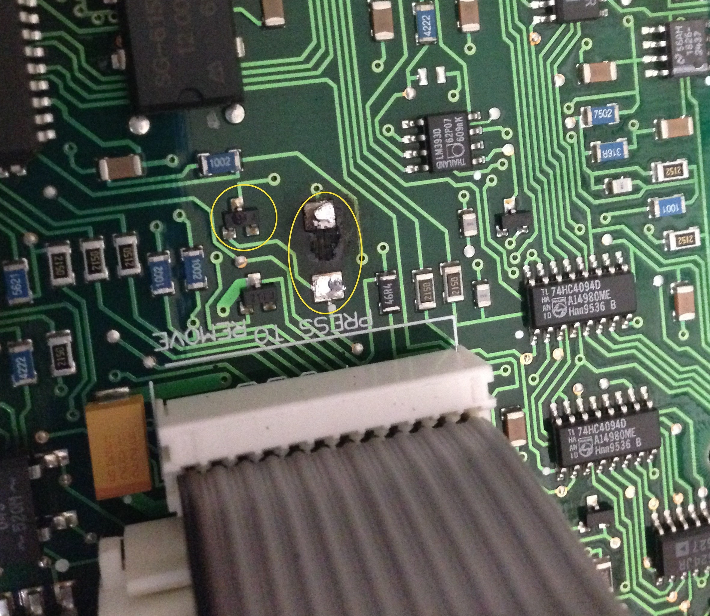
Tracing the circuit from U5 showed that this pin was connect too… nothing. It lead to an unplaced component E300. E301 sits on one of the other 3.3V supplies to the 69000, in almost exactly the same layout and is just a 0Ohm resistor. The other side of E300 was a 3.3v supply…

So I just shorted it as you can see in the picture below. I’m not sure why this wasn’t placed, perhaps VGA scope output was an optional extra on this model?
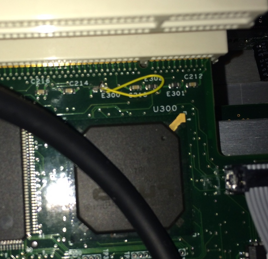
DACVCC

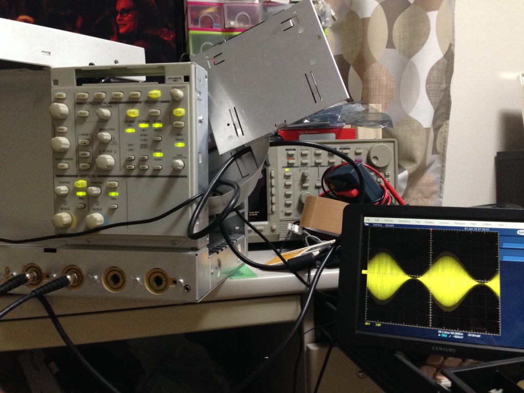
Once this was in place I could see a waveform on the scope (PCI/69000) VGA output:
tds5000ext

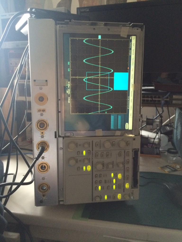
I also probed the LCD output, data was present, and there where no components in line between the 69000 and the LCD (a NL6448BC33-46) that would have failed. I ordered a replacement and success! Everything works fine:
tds5000ok

Chips and Technologies 69000 datasheet: m69000
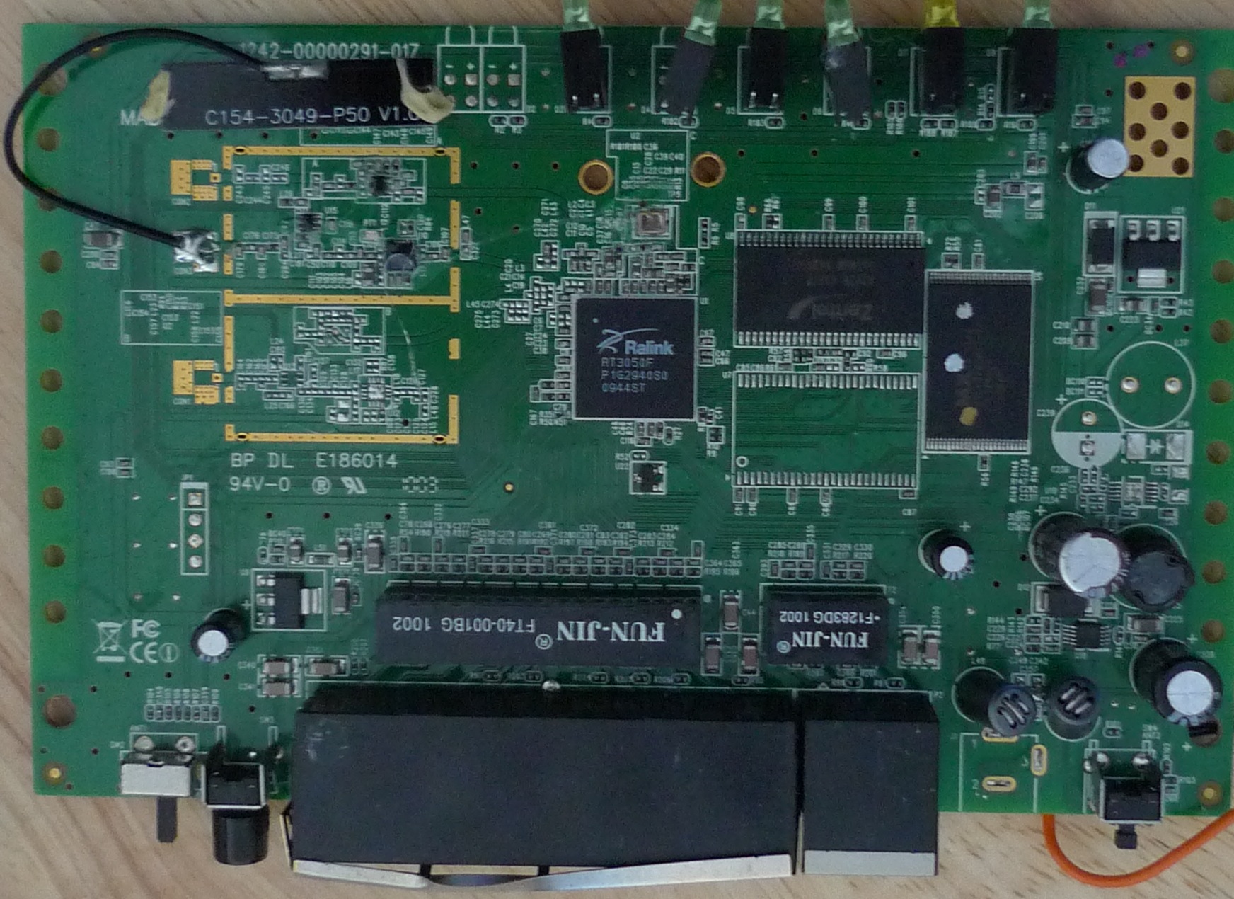
A RT3050 PCB

rt3050board

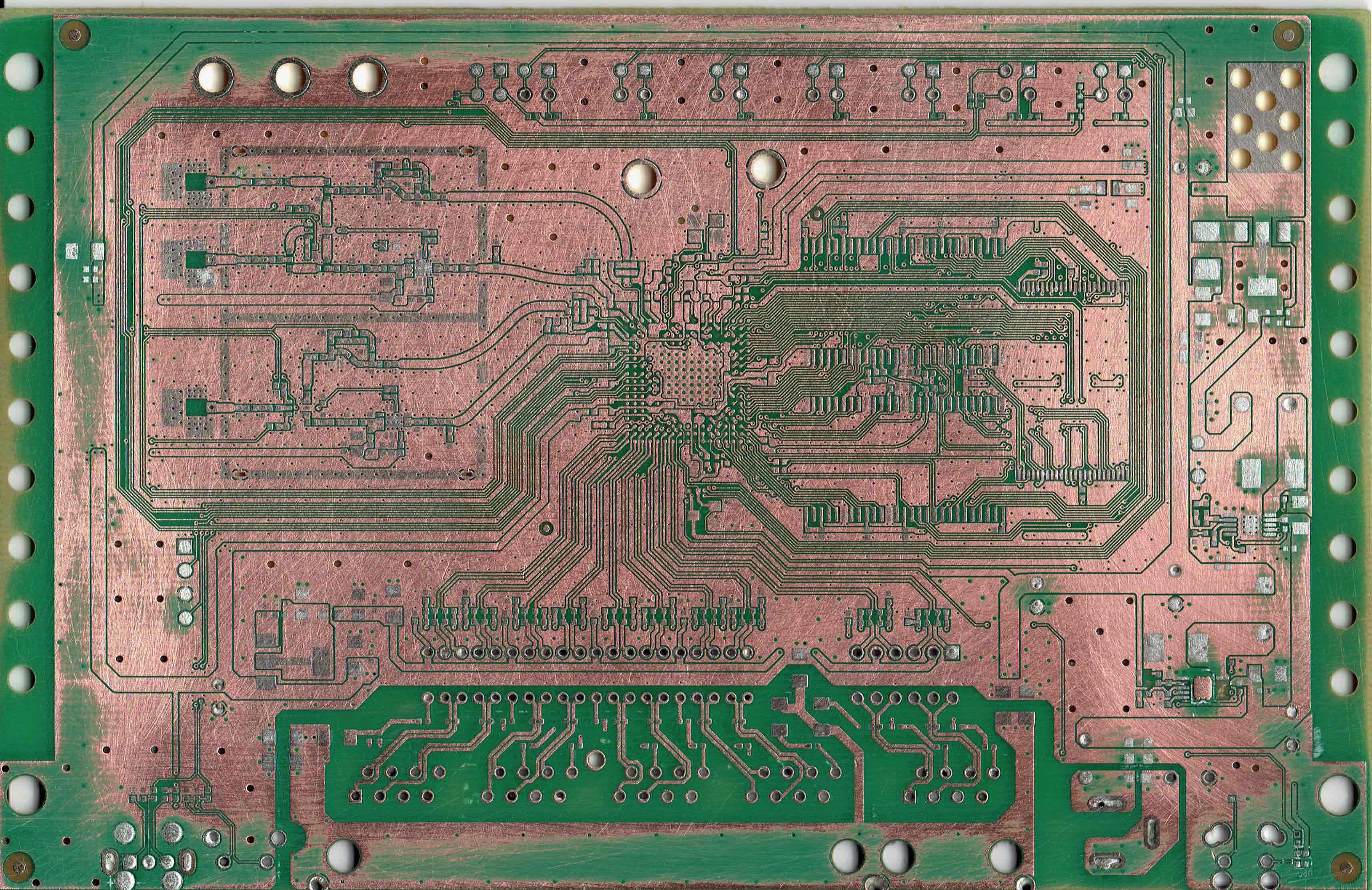
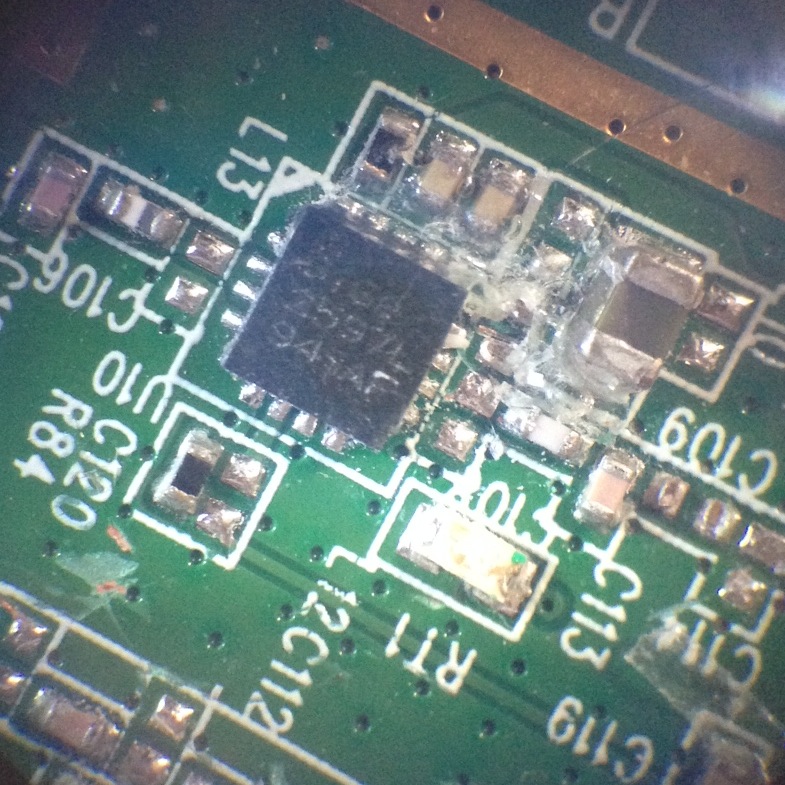
So I removed the components with a hot air rework tool, and once that was done I stuck the board in a scanner. It was still a little hard to see the traces under the silkscreen and mask so I sanded most of it off.

Here’s the board with most of the silkscreen and mask sanded off.
sand1

And with most of it still intact:

scratched1

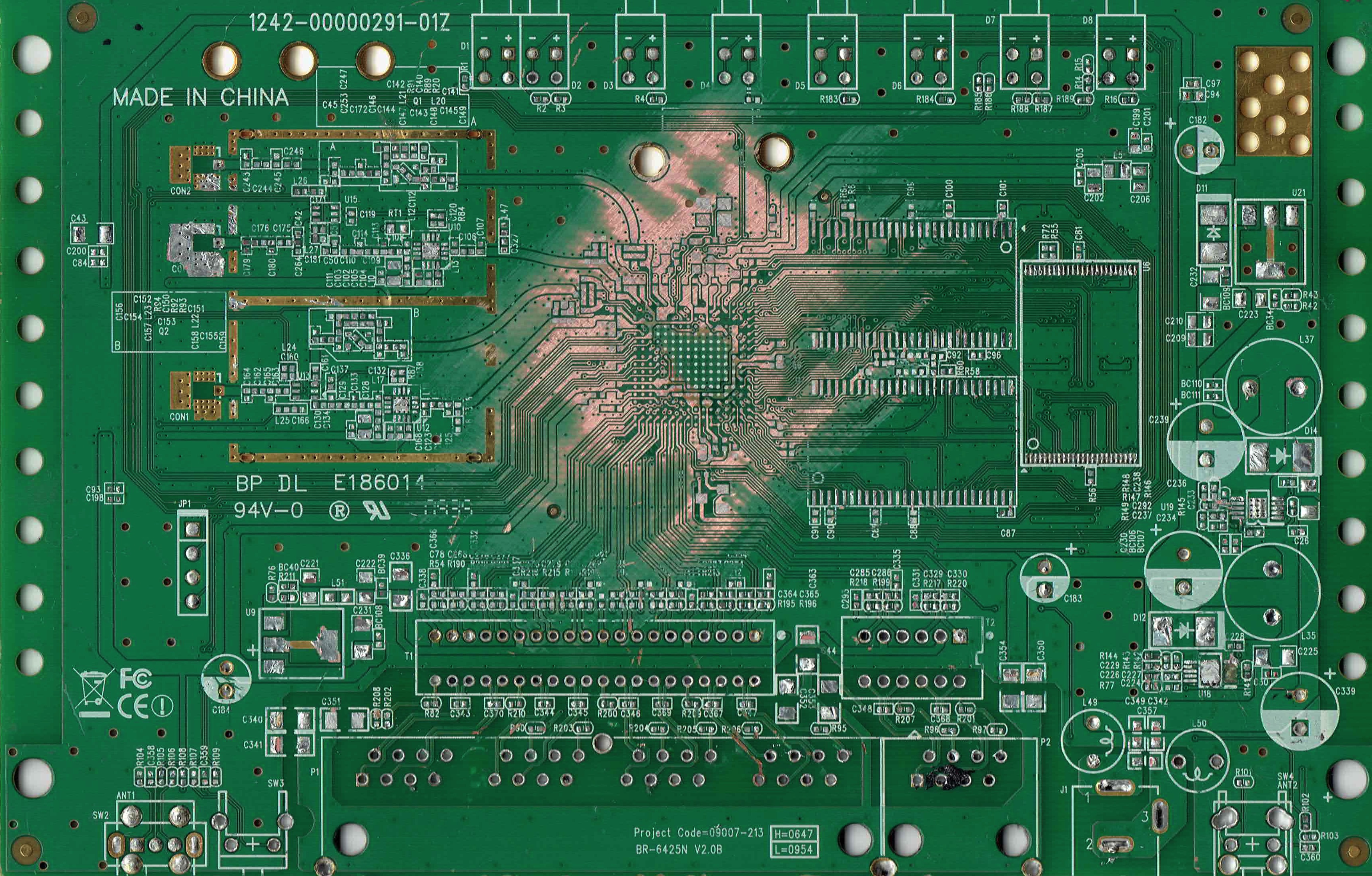
front

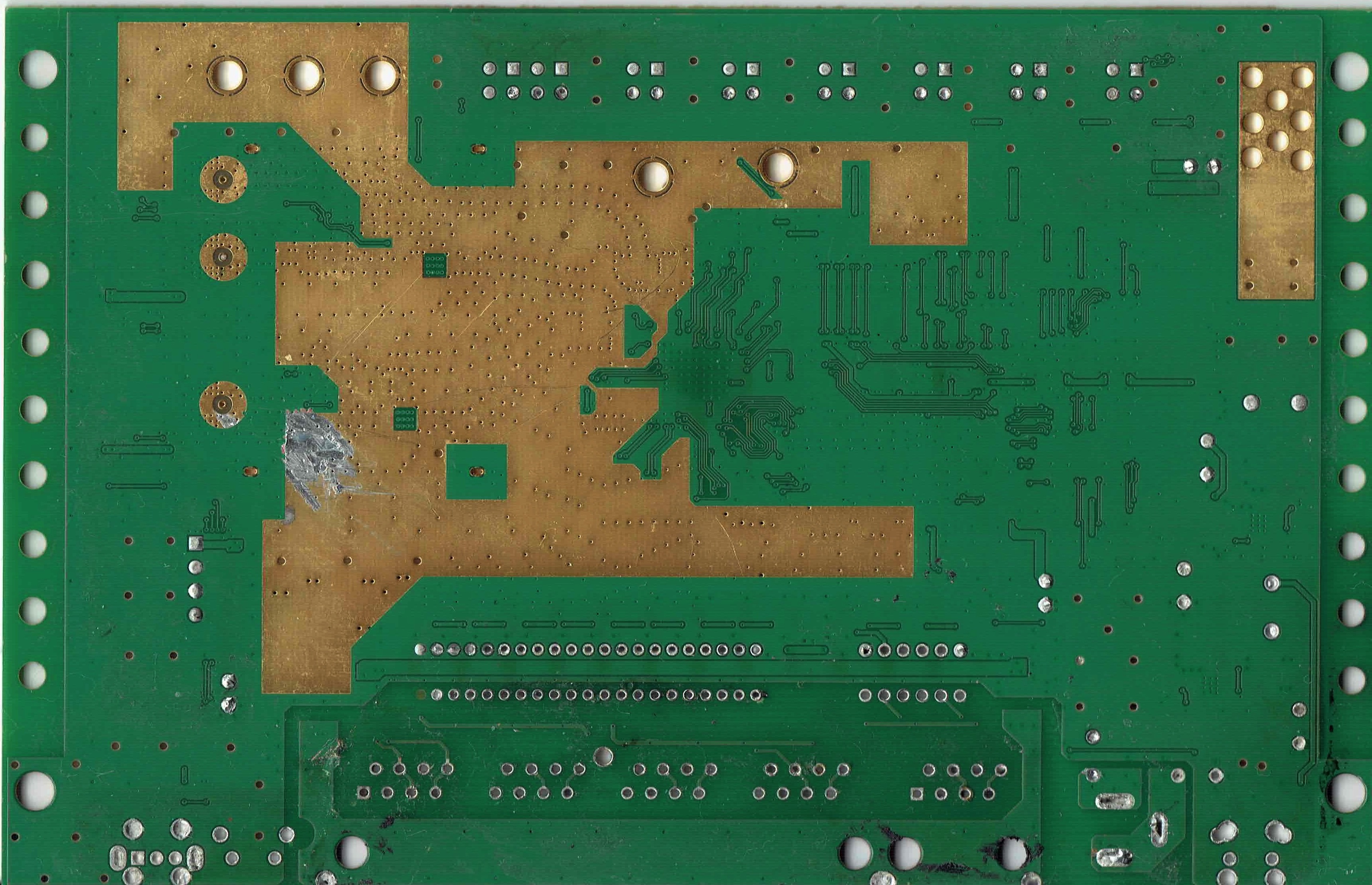
The backside image has been flipped horizontally so the images can be overlaid.

back

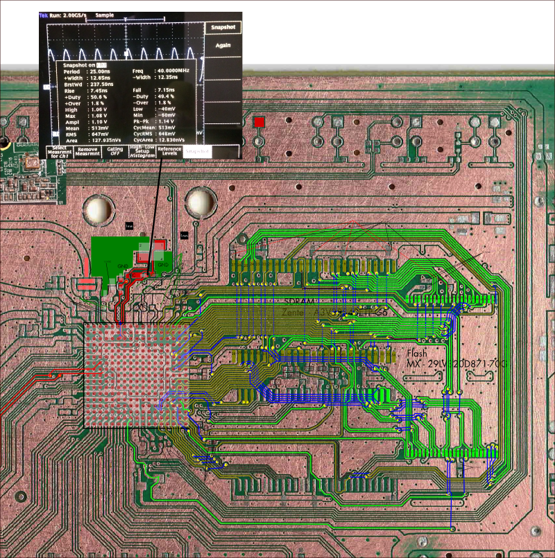
This SVG contains the layers aligned, and a bunch of the traces mapped out/annotated:

rt3050p

RT3050.svg

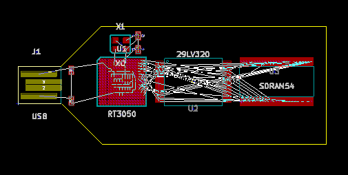
I’ve also been putting a kicad design together based on this chip, you can find the files here:

rt3050layout

rt3050.tar

A few other random images of the original PCB:

RT3050_CPU

rt3050xl

Useful datasheets:

150-30732-EN29LV320

RT3050_5x_V2.0_081408_0902

I couldn’t find a datasheet for the Zentel A3V28S40ETP-G6 on this board, however it seems to be similar to the M12L128168A:

M12L128168A

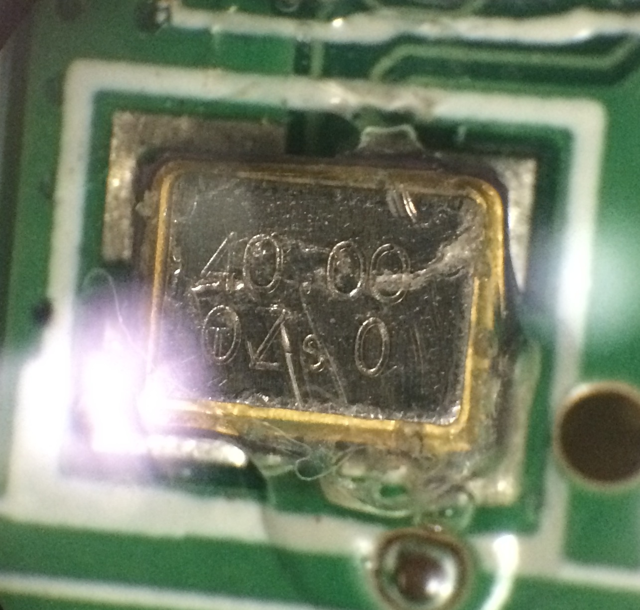
The crystal on this board seems to be a SMD3225 layout, I guess similar to this part:

smd3225

AIC809-29PU, RA29P:

RA29P

EH11A – AZ1117 (LM1117?)

DSA00153748

HuanLin480ApplicationNote

SIGe 2597L (Skyworks, 2.4GHz amp):

SIGe2597L

SIGe2597L

Tektronix TDS7054 Repair

I picked up a TDS7054 as junk for 200USD the other day. This was a pretty good deal considering the original list price was >20000USD, and they still go for 5000USD on ebay regularly. This post documents the fault and repair. When powered on the instrument wouldn’t display anything on either the scope VGA or the PC VGA interfaces. The TDS7000 and TDS5000 series scopes have kind of a weird architecture. They are effectively standard x86 PCs coupled with a PowerPC system running VXWorks which interfaces with the acquisition hardware and I guess does most of the signal analysis work.

The PowerPC system is attached to the x86 system via a PCI bus, from is connected to the acquisition and powersupply via a backplane. The following block diagram describes the setup:

TDS5000_2

Physically the boards are sit on top of each other, the x86 host on the top, the PowerPC board directly under that connected via the PCI bus and the acquisition and power supply under this. This makes debugging pretty difficult, as the PowerPC hardware wont power up without the x86 board in place. Luckily the fault I had was pretty straightforward. The diagram below shows the physical layout:

TDS7000_1

Debugging is further complicated by the fact that the PC has 2 video adapters, one that is directly on the x86 motherboard, and another which sits on the PCI bus and is attached to the scope hardware. The PowerPC and x86 hardware share the PCI graphics card (as far as I can tell) and the PowerPC is able to write data directly to the framebuffer there (and this is how it plots scope traces, at least this appears to be the case of the TDS5000). The PowerPC also somehow shares access to the HDD, and loads Vxworks from this, the HDD being connected to the PCI (and other signals) connector that sits between the 2 boards.

Debugging

As mentioned the device showed nothing on either VGA port at first. In order to get any output I needed to do a CMOS RAM reset on the PC hardware (there’s a CMOS RAM reset jumper next to the battery, or you can just remove the battery). After this is started outputting to it’s VGA port. However it wouldn’t see the HDD and just reported “A: Drive Error”. It would not enter the setup screen of the bios, even though the system said “Entering BIOS”. The motherboard has a modified BIOS to work with these scopes, and it seems like this is the cause of the weird behaviour.

My guess is that it couldn’t see the HDD because the PowerPC board wasn’t coming up correctly, after VXWorks boots, I believe it hands control of the HDD over to the x86 system.

The diagnostic 7-segment display showed “.A”. The “.” means that the diagnostic stopped at this point. The “A” is documented in the service manual as being an NVRAM check.

Next I attached a console to the serial port on the PowerPC board. It’s conveniently labeled “console” and the second and third pins from the top right provide a serial console ( 9600 8N1 ). This is a real (not TTL level) RS232 serial port, and most USB serial port adapters wont work (they run slightly out of spec and don’t provide a full 12 volt swing). I had to dig out an old PC with a real serial port for this.

The console showed the error below on the left. You can see the error where diagnostics failed “NV-MEMORY Walking-one test failed”. The screenshot on the right is what you should see (taken after the system was repaired).

scopefail

This indicated a fault accessing the NVRAM module. There’s a picture of this module here and this is my module with the “powercap” removed:

powercap

I checked it was receiving power, which is was and ordered a replacement module. Luckily after replacing the module, the diagnostic passed and the console output on the right of the picture above was shown. I also replaced the battery on the NVRAM module, which was low.

However the scope didn’t boot. Next the CMOS settings need resetting, and you still can’t enter the BIOS config on boot. For this you need a DOS boot floppy! You’ll also need some files from the system from the system HDD. The CMOS programming tool you need is in the following location: C:\Tektronix\CMOS (from memory). I attached the PATA drive via a USB converter to a PC and copied the files. However seeing as it’s been about 10 years since I had a DOS boot disc that was more challenging, I managed to find a USB floppy drive and some discs and somehow put a working bootdisc together and copied over the CMOS programming utility. I then booted from this and used CMOS.EXE -r NONET (again from memory) to restore the CMOS setting.

After this the system booted successfully:

scopefix

The reassembled scope is awesome, but pretty huge. It now lives out on Tokyo Hacker Farm, where I hope it will get some good use!

This EEVBlog forum entry was also very helpful and has a bunch of useful information, he also wrote up his notes here.

Siglent SDG1020 Arb data format

The Siglent SDG1020 comes with a wave form generating package for Windows XP and Vista. It’s called EasyWave. In order to install this you’ll need the NI VISA runtime (otherwise you’ll get a rather un-descriptive error saying “VISA32.DLL could not be found”. Once installed you can draw waveforms and either save them to a USB stick or program them to the device over USB (though I’ve never tried this).

However the file format appears to just be a modified CSV of the following format (and yes, the typo is written by the supplied software tool). It appears to be a DOS formatted file. A full example file is here

data lenth,16384
frequency,0.100000000
amp,20.000000000
offset,0.000000000
phase,0.000000000

xpos,value
0.000000e+000.6f,-0.974930362
6.103516e-004.6f,-0.972382425
1.220703e-003.6f,-0.969834487
1.831055e-003.6f,-0.967286550
2.441406e-003.6f,-0.964738613
3.051758e-003.6f,-0.962190675
3.662109e-003.6f,-0.959642738

9.996338e+000.6f,-0.974930362
9.996948e+000.6f,-0.974930362
9.997559e+000.6f,-0.974930362
9.998169e+000.6f,-0.974930362
9.998779e+000.6f,-0.974930362
9.999390e+000.6f,0.000000000