Tektronix TDS7054 Repair
I picked up a TDS7054 as junk for 200USD the other day. This was a pretty good deal considering the original list price was >20000USD, and they still go for 5000USD on ebay regularly. This post documents the fault and repair. When powered on the instrument wouldn’t display anything on either the scope VGA or the PC VGA interfaces. The TDS7000 and TDS5000 series scopes have kind of a weird architecture. They are effectively standard x86 PCs coupled with a PowerPC system running VXWorks which interfaces with the acquisition hardware and I guess does most of the signal analysis work.
The PowerPC system is attached to the x86 system via a PCI bus, from is connected to the acquisition and powersupply via a backplane. The following block diagram describes the setup:
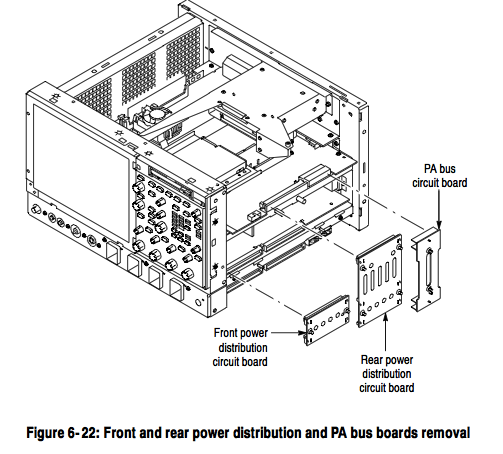
Physically the boards are sit on top of each other, the x86 host on the top, the PowerPC board directly under that connected via the PCI bus and the acquisition and power supply under this. This makes debugging pretty difficult, as the PowerPC hardware wont power up without the x86 board in place. Luckily the fault I had was pretty straightforward. The diagram below shows the physical layout:
Debugging is further complicated by the fact that the PC has 2 video adapters, one that is directly on the x86 motherboard, and another which sits on the PCI bus and is attached to the scope hardware. The PowerPC and x86 hardware share the PCI graphics card (as far as I can tell) and the PowerPC is able to write data directly to the framebuffer there (and this is how it plots scope traces, at least this appears to be the case of the TDS5000). The PowerPC also somehow shares access to the HDD, and loads Vxworks from this, the HDD being connected to the PCI (and other signals) connector that sits between the 2 boards.
Debugging
As mentioned the device showed nothing on either VGA port at first. In order to get any output I needed to do a CMOS RAM reset on the PC hardware (there’s a CMOS RAM reset jumper next to the battery, or you can just remove the battery). After this is started outputting to it’s VGA port. However it wouldn’t see the HDD and just reported “A: Drive Error”. It would not enter the setup screen of the bios, even though the system said “Entering BIOS”. The motherboard has a modified BIOS to work with these scopes, and it seems like this is the cause of the weird behaviour.
My guess is that it couldn’t see the HDD because the PowerPC board wasn’t coming up correctly, after VXWorks boots, I believe it hands control of the HDD over to the x86 system.
The diagnostic 7-segment display showed “.A”. The “.” means that the diagnostic stopped at this point. The “A” is documented in the service manual as being an NVRAM check.
Next I attached a console to the serial port on the PowerPC board. It’s conveniently labeled “console” and the second and third pins from the top right provide a serial console ( 9600 8N1 ). This is a real (not TTL level) RS232 serial port, and most USB serial port adapters wont work (they run slightly out of spec and don’t provide a full 12 volt swing). I had to dig out an old PC with a real serial port for this.
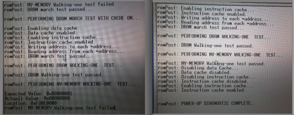
The console showed the error below on the left. You can see the error where diagnostics failed “NV-MEMORY Walking-one test failed”. The screenshot on the right is what you should see (taken after the system was repaired).
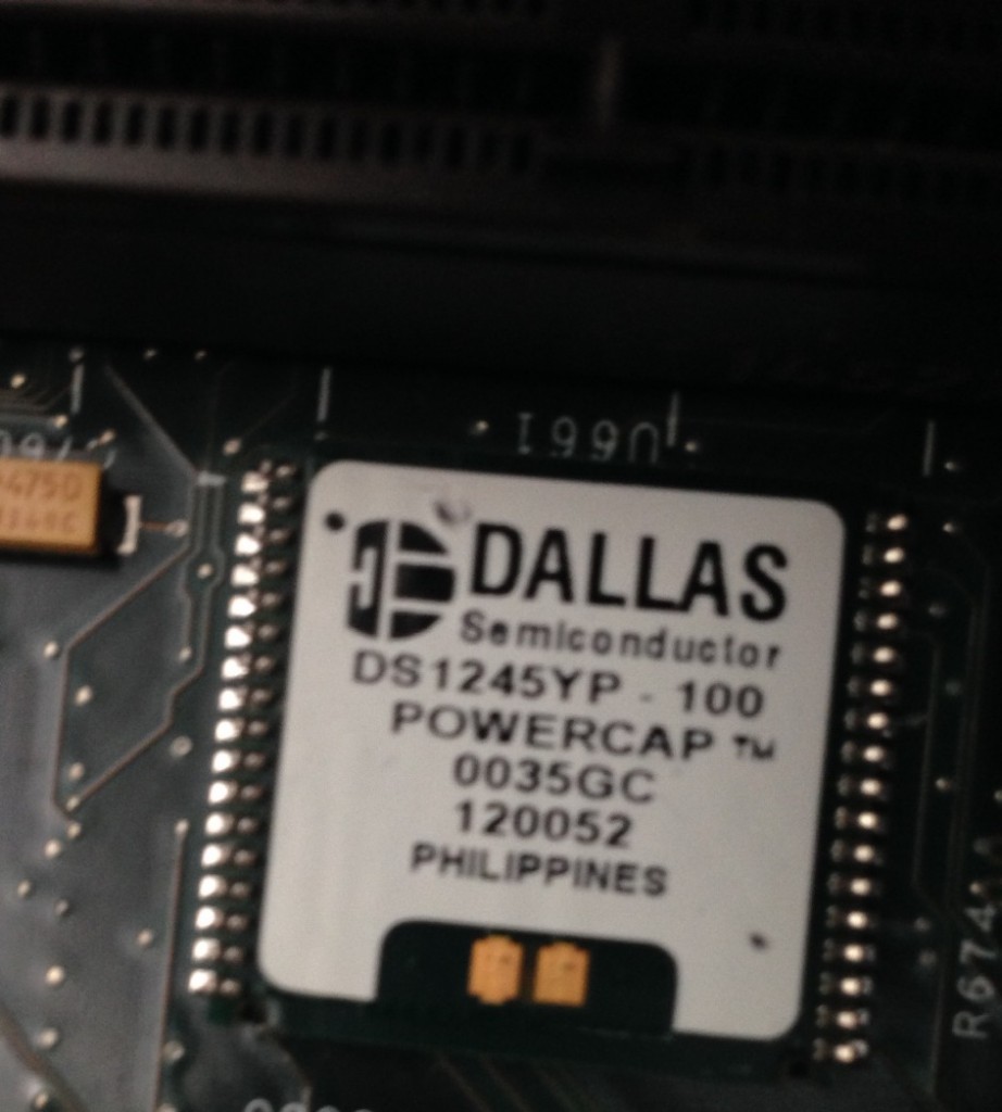
This indicated a fault accessing the NVRAM module. There’s a picture of this module here and this is my module with the “powercap” removed:
I checked it was receiving power, which is was and ordered a replacement module. Luckily after replacing the module, the diagnostic passed and the console output on the right of the picture above was shown. I also replaced the battery on the NVRAM module, which was low.
However the scope didn’t boot. Next the CMOS settings need resetting, and you still can’t enter the BIOS config on boot. For this you need a DOS boot floppy! You’ll also need some files from the system from the system HDD. The CMOS programming tool you need is in the following location: C:\Tektronix\CMOS (from memory). I attached the PATA drive via a USB converter to a PC and copied the files. However seeing as it’s been about 10 years since I had a DOS boot disc that was more challenging, I managed to find a USB floppy drive and some discs and somehow put a working bootdisc together and copied over the CMOS programming utility. I then booted from this and used CMOS.EXE -r NONET (again from memory) to restore the CMOS setting.
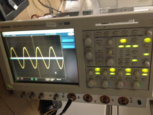
After this the system booted successfully:
The reassembled scope is awesome, but pretty huge. It now lives out on Tokyo Hacker Farm, where I hope it will get some good use!
This EEVBlog forum entry was also very helpful and has a bunch of useful information, he also wrote up his notes here.


[…] picked up another broken Tektronix scope for about 200USD scope the other day. This one had no output on any on […]
Good job on repairing your beast. I’d enjoy TDS7054 more than higher BW scopes, as your’s have 1M inputs and using usual BNC’s instead of expensive proprietary TekConnect.
Yes, the TDS7000 and TDS5000s are nice scopes. This 7000 now lives out in Japan but I use my 5000 every day. I also have a Waverunner 6050 but the Tektronix gets more use, I prefer the Tektronix interface I think.