Piezo actuators are extremely interesting for high performance, applications. They often provide 1000s of newtons of force at sub-nanometer resolution. They also respond extremely quickly, though often have a settling time and exhibit hysteresis which makes closed loop operation desirable.
I’ve been looking at these actuators for a personal project (generally I’ve been reading about the amateur STM and other SPM projects and keep thinking about having a go). This is a short review of the actuator types I’ve encountered so far.
Piezo stacks
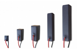
These devices use multiple layers of Piezo electric material connected in parallel in a stack. They provide deflection in the micron range, in general 10s to 100s of microns. Normal a drive voltage in the 100s of volts is required.
Stacks with flexual amplification are also available, and some of these can provide deflection close to the millimeter range for example these devices.
Unimorph discs
These are you basic Piezo buzzers. I’ve not seen accurate deflection measurements, what I’ve reads suggests a deflection of 1 or 2 microns. Aside from the obvious audio applications they have also been used in micropumps.
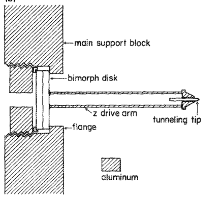
Because of their low cost, Piezo buzzers get used in a lot of hacker projects. For example this laser pointer imaging thing. They’ve also been cut into quadrants to give XY motion for STM projects (see image below) for example “2006-2314: A NANOTECHNOLOGY EXPERIMENT: DESIGN OF LOW COST SCANNING TUNNELING MICROSCOPES Nebojsa Jaksic, Colorado State University-Pueblo”
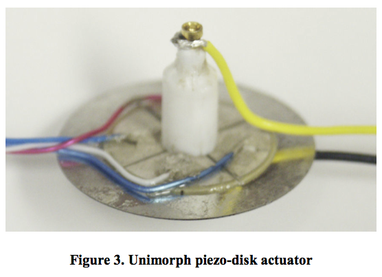
John Alexander’s project on the now defunct geocities also used the cut-up unimorph disc configuration and you can see more details on the waybackmachine archive of his pages.
Bimorph, Bimorph benders
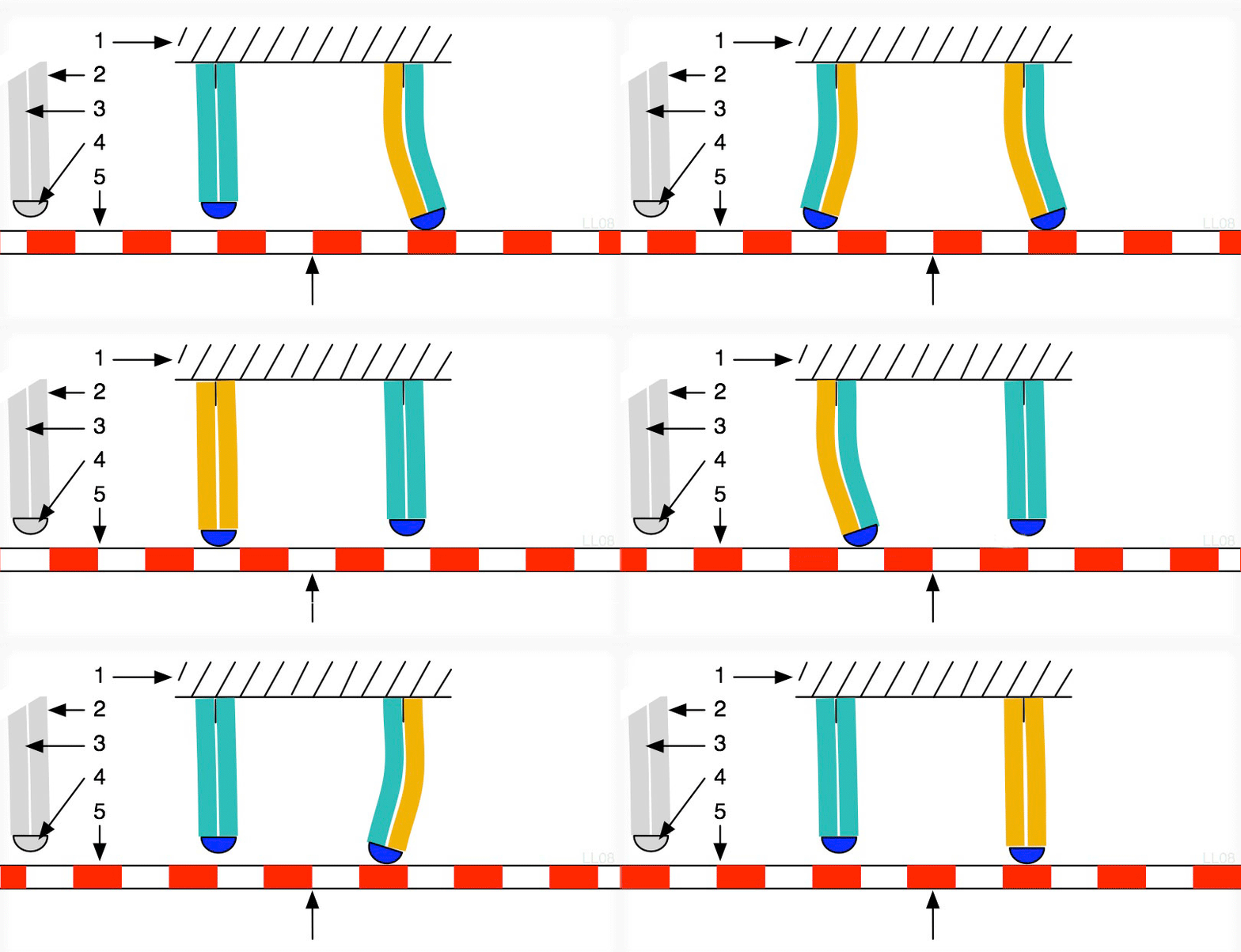
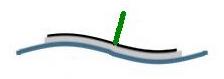
I couldn’t help but include the GIF from the wikipedia page because it’s so awesome. Bimorph actuators have two active layers, one that expands, and another that contracts.
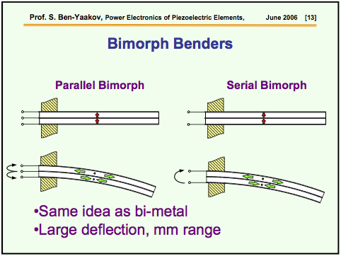
This slide deck has some useful information on Bimorphs (and is where the above slide comes from). I’d like to understand why/where these actuators are useful. They generally provide millimeters of deflection (and I would guess are often used in bending piezo actuators below).
Piezo tubes
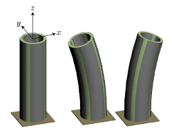
Piezo tubes are the standard precision XYZ approach mechanism used in most STMs. They provide XYZ motion in the 10s of microns. Again, they need a drive voltage of 100 to 200 volts. They seem to cost 200 to 500USD.
Slip-stick actuators
So called Slip-stick motors static and dynamic friction to turn the rotor. This is often described as being similar to the “table cloth trick”, if you pull the cloth quickly the tableware stays still. However if you pull the cloth slowly friction pulls all the tableware with the cloth and everything comes with it.
Slip-stick motors use this principle to rotate a rotor.
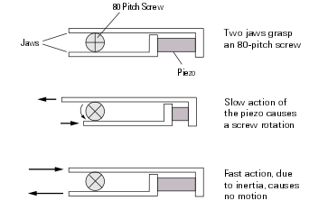
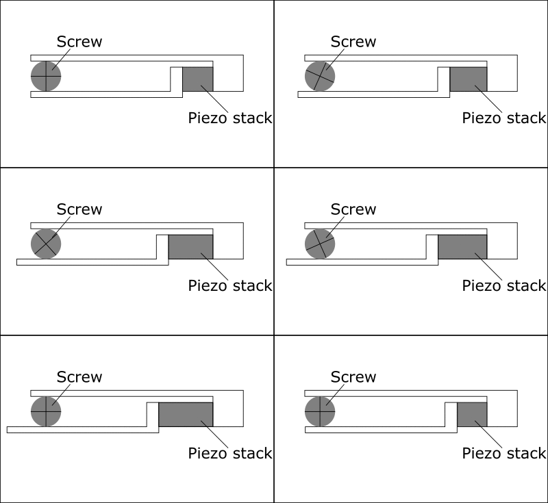
An Piezo stack rubs against a rotor in order to turn it. By extending slowly the stack pushes the rotor round. It then retracts quickly. The slow motion causes friction which transfers the motion to the rotor. However the quick retraction has little friction, causes no motion. The net effect is that the rotor rotates in discrete steps.
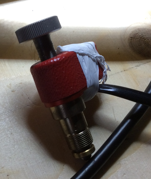
The stack can reverse the motion by using a quick extension and slow retraction. Picomotor appear the be the leading manufacturer of slip-stick motors. They supply two models with resolutions of 30 and 100nm.
Inchworms
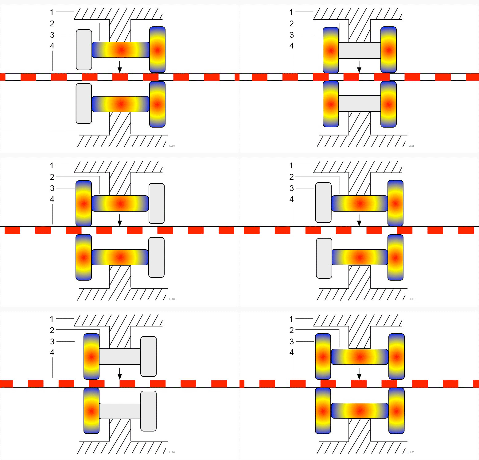
Have to include the wikipedia GIF again, because it’s cool! Inchworms use Piezo stacks to push a shaft along. This gives them all the advantages of a Piezo (nanometer resolution, large force, no vibration) but with relatively large deflection, really only limited by the length of the shaft. Typically they are available with 10 to 20 millimeters of deflection. They are however more expensive than some other actuators costing in the the 500+USD range, with some models significantly more expensive. They’ve also been applied to STMs among other precision applications.
Rotary
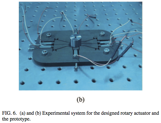
Rotary inchworms seems to be largely experimental, but I came across a paper on them recently so thought I’d include them here. Similar to inchworms in general they prod a spindle to slowly turning it.
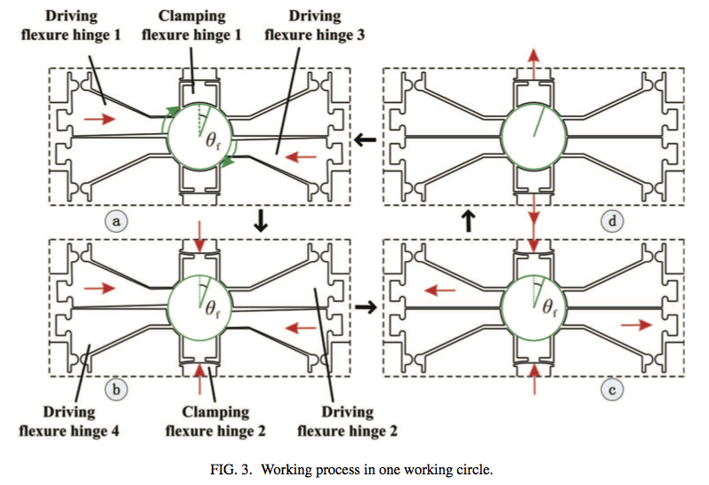
The schematic above from this paper. Shows the basic mechanism, force is applied using a Piezo stack to opposite “corners” of the spindle, which twists it round. Clamps on the top and bottom hold the spindle in place as the force is removed.
Seems rather neat! Not sure what the applications are!
See: Design and experiment performances of an inchworm type rotary actuator, Jianping Li, Hongwei Zhao, Mingkun Shao, Xiaoqin Zhou, Hu Huang, and Zunqiang Fan for more details.
LEGS
I strongly recommend you check out the video linked above, it’s awesome. LEGS (R) is a trademark of Piezomotor (R) I believe. They use a slightly different mechanism to the normal Inchworm, walking the shaft along, but have many of the advantages of the Inchworm providing sub-nanometer resolution over a 10 to 20mm range.
Bending Piezo Actuators
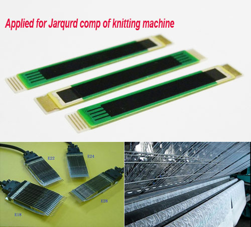
These actuators are available from a number of sources, I have some coming from PantPiezo for a personal project. They appear to offer huge displacement (in the millimeter range) but low blocking force (<1N). They also appear to be /very/ low cost (<<20USD).


 RSS
RSS