MSP430 2013 with 3310 Nokia LCD
I’ve started playing with the Nokia 3310 LCD. It’s similar to the LCD I used in my watch project but is black and white only. It’s a little clearer to read, and hopefully consumes less power.
I’d ordered a pack of 7 nokia 3310 LCDs from the internet. However after I disassembled the nokia packaging I noticed there were actually 3 different LCD types present:
One didn’t have metal contacts, only glass ones. The other, with the smaller IC I spent a long time fiddling with, and couldn’t get anything to display on. It could be that my wiring was dodgy but I’ve also known LCDs for the same phone to behave differently. Nokia have been known to use different LCDs in their phones and include detection logic to figure out how to drive it. Anyway… the LCD with the larger controller worked, and if you are considering using a 3310 display I’d recommend you try and find this type.
I used the code from here as my basis. I removed a lot of his project specific logic and added my own simple test code.
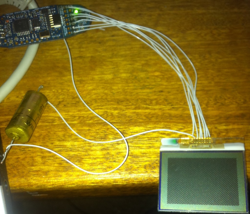
Here’s the setup:
That cap does seem to be required. The 3510i LCD works without one, I might do some more experimentation with this.
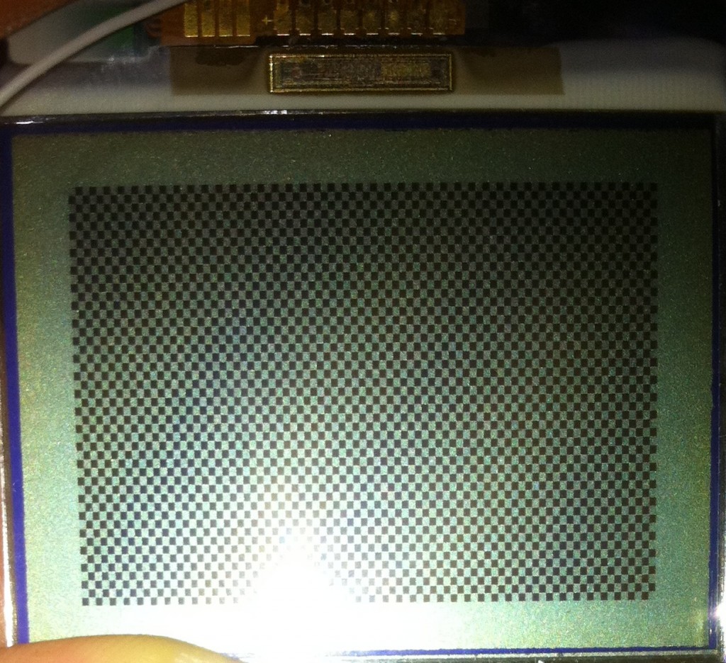
And here’s what the code outputs:
And here’s the code! Again, largely due to TopHatHacker, with some trimming down and a few modifications:
#define F_CPU 1000000UL
#include <io.h>
#include <signal.h>
#define SEND_CMD 0
#define SEND_CHR 1
#define LCD_X_RES 84
#define LCD_Y_RES 48
#define COUNTDOWN 1
// defines for 4250 pin connections to Nokia 3310
#define SCEPORT P1OUT
#define SDINPORT P1OUT
#define DCPORT P1OUT
#define SCKPORT P1OUT
#define RESPORT P1OUT
#define SCE BIT5 // LCD pin 5 (enable)
#define SDIN BIT3 // LCD pin 3 (data)
#define DC BIT4 // LCD pin 4 (Data enabled)
#define SCK BIT1 // LCD pin 2 (Data clock)
#define RES BIT2 // LCD pin 8 (reset)
void LCDSend(unsigned char,unsigned char);
void LCDClear(void);
void LCDInit(void);
void LCDBlack(void);
void LCDCurs(unsigned char,unsigned char);
void LCDSend(unsigned char data, unsigned char cd) {
volatile unsigned char bits;
unsigned short cnt=8;
// assume clk is hi
// Enable display controller (active low).
SCEPORT &amp;amp;amp;= ~SCE; //RESET SCE
// command or data
if(cd == SEND_CHR) {
DCPORT |= DC; //set to send data
}
else { // reset to send command
DCPORT &amp;amp;amp;= ~DC;
}
///// SEND SPI /////
bits=0x80; // bits is mask to select bit to send. select bit msb first
//send data
while (0<cnt--)
{
// put bit on line
// cycle clock
SCKPORT &amp;amp;amp;= ~SCK;
if ((data &amp;amp;amp; bits)>0) SDINPORT |= SDIN; else SDINPORT &amp;amp;amp;= ~SDIN;
//Delay(1);
SCKPORT |= SCK;
//Delay(2);
// SHIFT BIT MASK 1 right
bits >>= 1;
}
// Disable display controller.
SCEPORT |= SCE;
}
void LCDClear(void) {
int i,j;
LCDSend(0x80, SEND_CMD );
LCDSend(0x40, SEND_CMD );
for (i=0;i<6;i++) // number of rows
for (j=0;j<LCD_X_RES;j++) // number of columns
LCDSend(0x00, SEND_CHR);
}
void LCDInit(void)
{ // assume ports set up and initialized to output
// Reset LCD
SCEPORT &amp;amp;amp;= ~SCE; // RESET SCE to enable
// toggle RES
RESPORT |= RES; // Set RES
char l;
for(l=0;l<100;l++)
l=l;
RESPORT &amp;amp;amp;= ~RES; // reset RES
for(l=0;l<100;l++)
l=l;
RESPORT |= RES; // Set RES
// Cycle Clock
SCKPORT &amp;amp;amp;= ~SCK;
SCKPORT |= SCK;
// Disable display controller.
SCEPORT |= SCE; // bring high to disable
for(l=0;l<100;l++)
l=l;
// Send sequence of command
LCDSend( 0x21, SEND_CMD ); // LCD Extended Commands.
LCDSend( 0xC8, SEND_CMD ); // Set LCD Vop (Contrast).
LCDSend( 0x06, SEND_CMD ); // Set Temp coefficent to 2.
LCDSend( 0x13, SEND_CMD ); // LCD bias mode 1:100.
LCDSend( 0x20, SEND_CMD ); // LCD Standard Commands, Horizontal addressing mode.
LCDSend( 0x08, SEND_CMD ); // LCD blank
LCDSend( 0x0C, SEND_CMD ); // LCD in inverse mode.
LCDClear();
}
void lcdcontrast(char c) {
LCDSend( 0x21, SEND_CMD ); // LCD Extended Commands.
LCDSend( c, SEND_CMD ); // Set LCD Vop (Contrast).
LCDSend( 0x20, SEND_CMD ); // LCD Standard Commands, Horizontal addressing mode.
}
void LCDCurs(unsigned char x, unsigned char y)
{
LCDSend(0x80|x,SEND_CMD);
LCDSend(0x40|y,SEND_CMD);
}
void LCDDot()
{
int lm;
LCDSend(0x00,SEND_CHR);
LCDSend(0x00,SEND_CHR);
LCDSend(0x00,SEND_CHR);
for(lm=0;lm<3;lm++)
LCDSend(0xFF,SEND_CHR);
}
int main(void)
{
WDTCTL = WDTPW + WDTHOLD; // Stop WDT
P1DIR = 0xFF;
BCSCTL1 = CALBC1_1MHZ; // Set range
DCOCTL = CALDCO_1MHZ; // Set DCO step + modulation
BCSCTL2 = 0xF8;
BCSCTL3 = LFXT1S_0 + XCAP_3;
CCTL0 = CCIE;
CCR0 = 0;
TACCR0 = 0x3FF;
TACTL = 0x0211;
LCDInit();
_BIS_SR(GIE);
// draw cross pattern
char v = 0xAA;
for(int x=0;x<((84*48)/8);x++) {
LCDSend(v,SEND_CHR);
v = v ^ 0xFF;
}
for(;;);
}
[/sourcecode]
<h2>Notes</h2>
MSP430 pinout:
<a href="http://41j.com/blog/wp-content/uploads/2011/09/MSP430F2011-pinout.jpg"><img src="http://41j.com/blog/wp-content/uploads/2011/09/MSP430F2011-pinout.jpg" alt="" title="MSP430F2011-pinout" width="398" height="129" class="aligncenter size-full wp-image-241" /></a>
LCD pinout and AVR code <a href="http://www.quantumtorque.com/content/view/32/37/">here</a>.
Other 3310 projects:
With a larger MSP430: <a href="http://tophathacker.com/?p=40">here</a> and <a href="http://320volt.com/msp430-nokia-3310-lcd-direnc-hesaplayici-yeniden/">here</a>
Various nokia LCD pinouts <a href="http://www.module.ro/nokia_3510.html">here</a>
The code is compiled as:
[sourcecode language="bash"]
~/msp430/bin/msp430-gcc -Os -Wall -mmcu=msp430x2013 -std=gnu99 -o main.elf main.o
MSPDebug is used to program the device. run as:
mspdebug uif -d /dev/ttyUSB0
MSPDebug is launched type: prog main.elf to program, run to run.


