The iPhone MEMS Mic in a SEM
iPhone MEMS Mic SEM Image
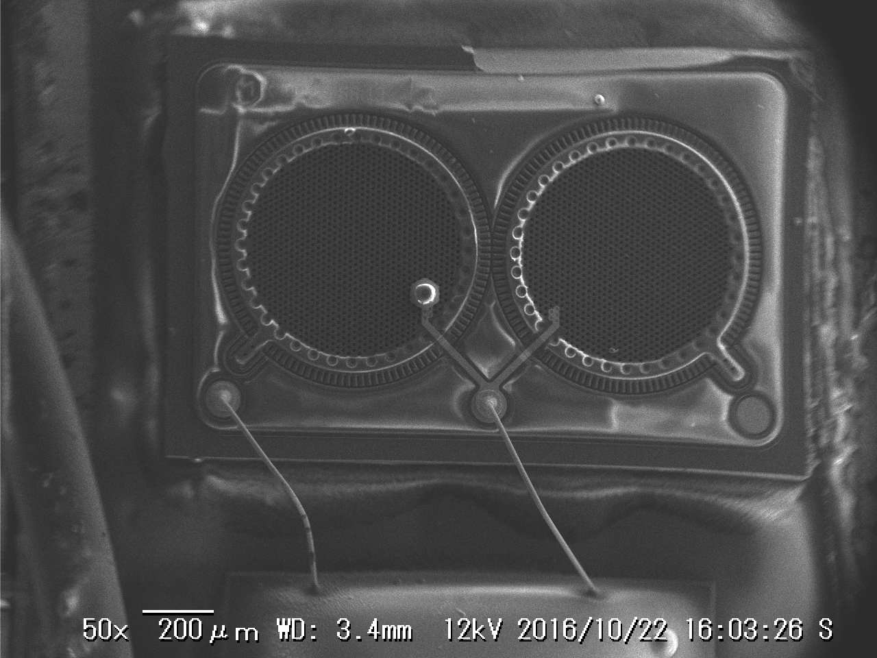
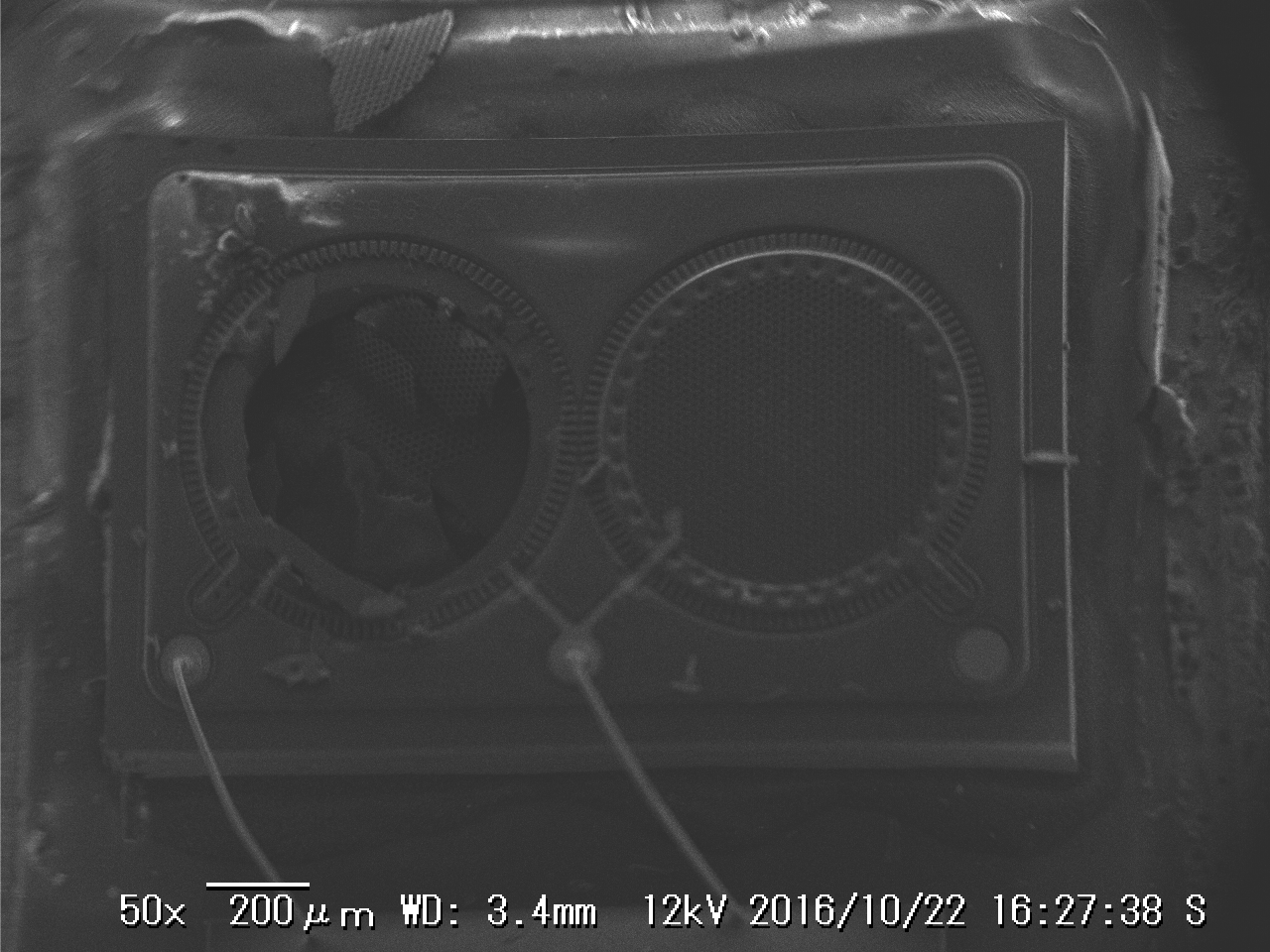
SAfter playing with the BME280 I have this new fetish for all things MEMS. So today I decided to stick the iPhone 6s MEMS mic in the SEM. According to the always wonderful chipworks this is the Knowles KSM1.
The chipworks optical die image is shown below and it clearly looks very similar to the SEM image to the right.
The die seems to contain few sub-diffection limit features. The smallest features seem to be on the order of a few microns, and I assume you could make this with a 1 micron process.
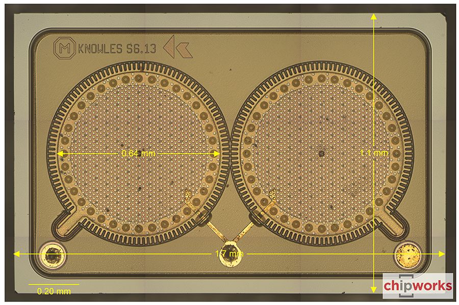
iPhone MEMS Mic optical image (from chipworks)
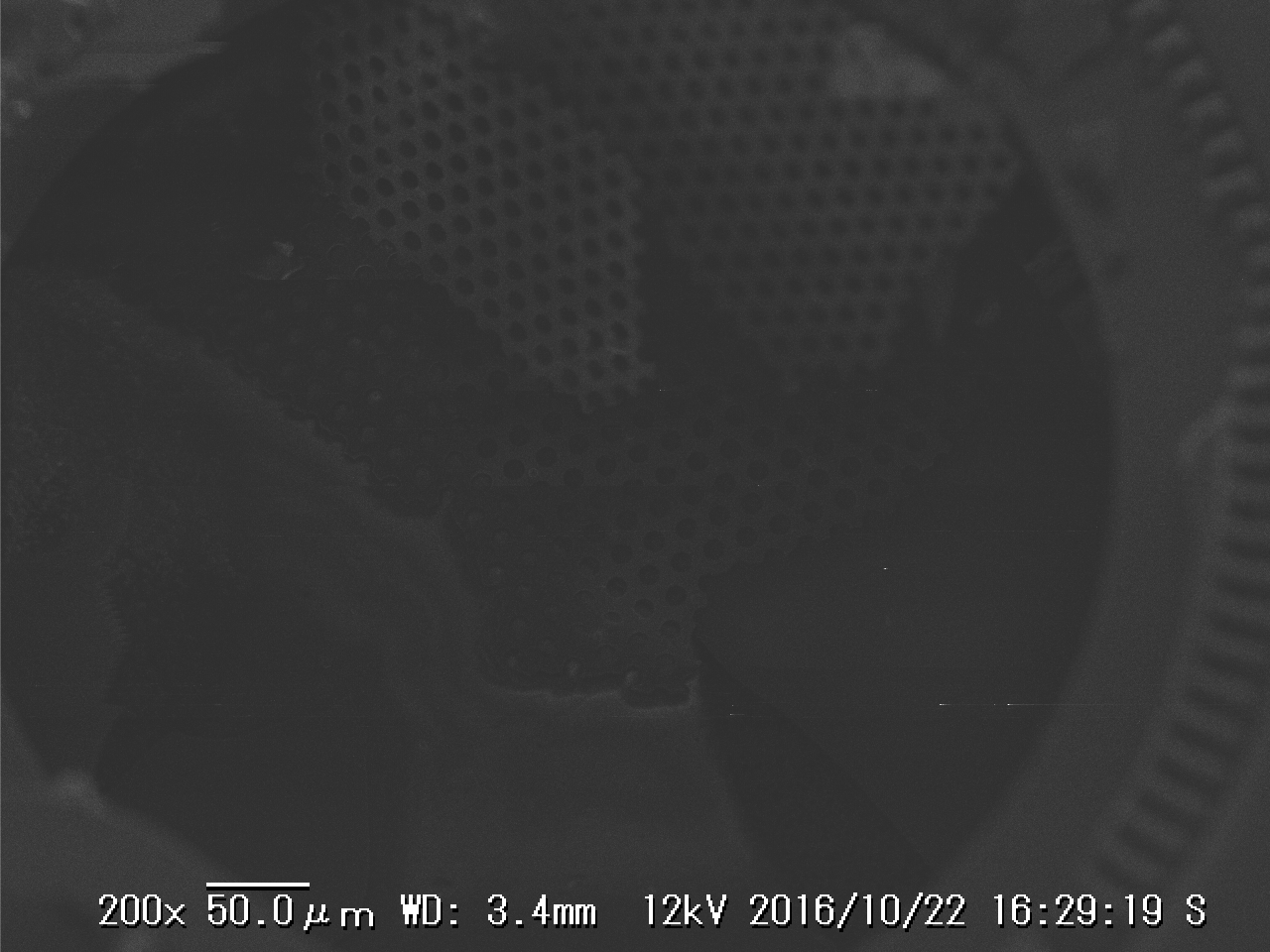
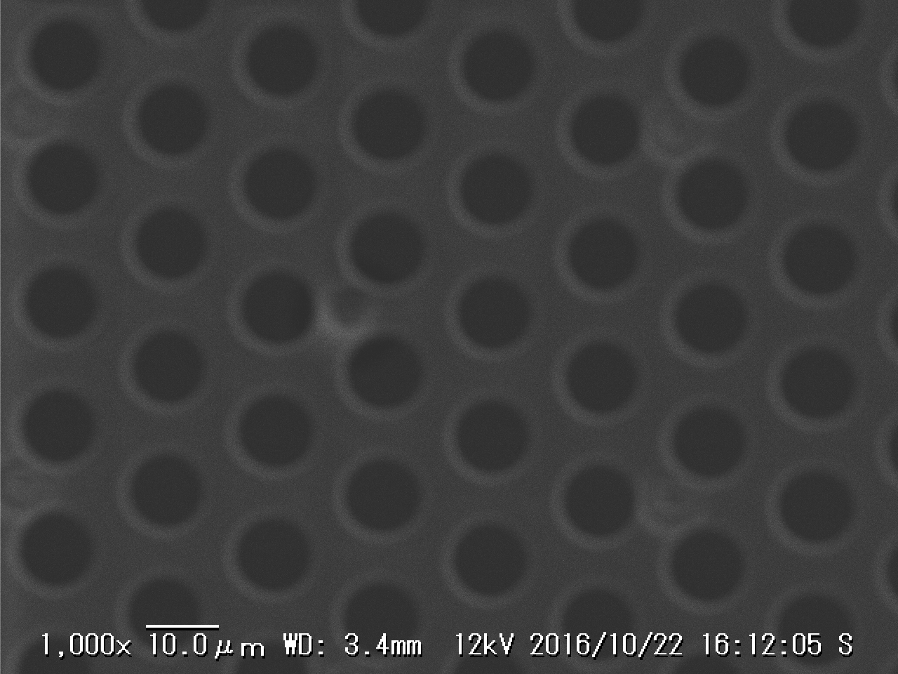 I was really interested in the patterning on the diaphragm. The patterning of these circles differs slightly between my SEM images and the chipworks optical image above. In fact on the SEM image they look a lot more like holes. Some Knowles patents refer to holes’ purpose as allowing a void to be etched under the diaphragm:
The perforated member contains a number of openings 21 through which a sacrificial layer (not shown) between the diaphragm and perforated member is etched during fabrication to form the air gap
Makes sense to me!
 The “holes” are about 10micron in diameter, pretty huge really! On another device I’d poked tweezers through one of the diaphragms. My hope was I’d either get some notion of the layer thickness or revel the structure below the diaphragm (if any). No such luck really. Other than it’s probably super-thin!
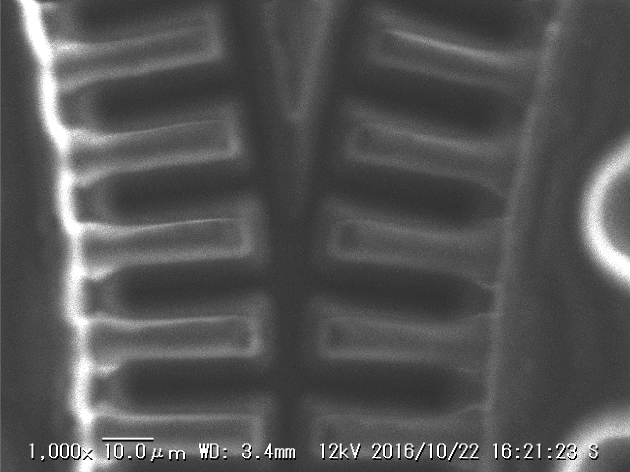
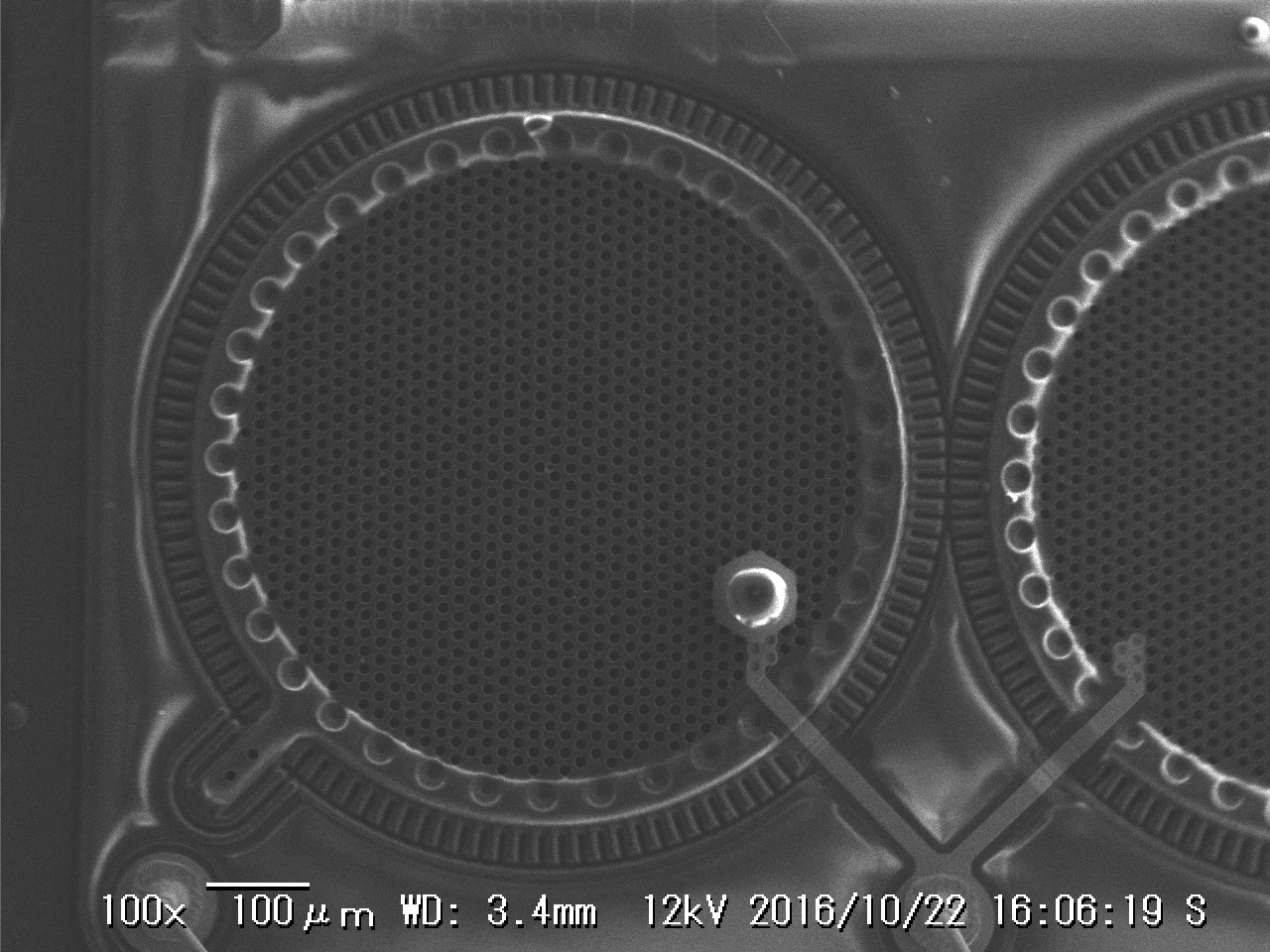
 Below are a couple more images for your viewing pleasure. The bits sticking out below, I assume are anchor points. It’s interesting that in the image above, the diaphragm breaks right up until these anchors. So it seems it does extend all the way to this point.
The overall construction seems straightforward (well, as awe inspiring as MEMS always is). But there are a few questions I still have… like why are there 2 diaphragms ? Is that a yield issue or a signal issue? What are the larger circles at the edge of the diaphragm? What’s the bit that sticks out to make the diaphragm Q shaped? And why is the bonding to the diaphragm seeming different on the left than the right… many questions which perhaps I’ll investigate if I find time (update: see below).
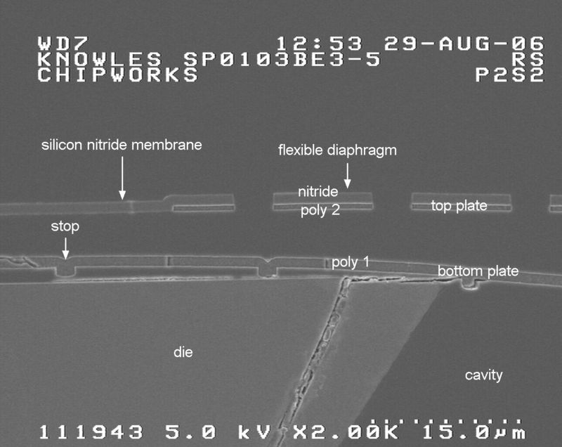
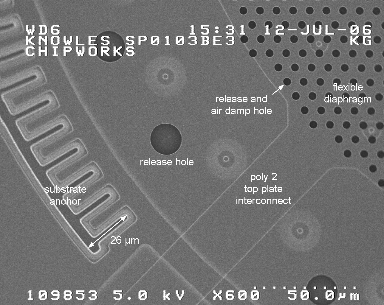 So… this MEMS journal post has a bunch of useful information. In the image to the right you can see they’ve labeled most of the features.
This is great, but the second cross-sectional view helped even more (see below).The microphone is a capacitor whose capacitance varies, initially I was thinking that the diaphragm and the bottom of the cavity formed the capacitor. That’s not the case.
There are actually two thin layers fabricated on top of each over above the main cavity, that’s why on the SEM images you see two connection points, the bit that looks like part of an inverted ‘Q’ is going to the top plate. The central connection to the bottom. One final question I have then is how is the main cavity formed? And why is it needed? The bottom plate doesn’t look like it has release holes in it, and could it not be fixed?