December 10, 2014, 1:43 pm
Yesterday I took a look at a phase shift oscillator. The design I showed used a capacitor in a low pass configuration. I explained why this caused a phase shift allowing us to construct an oscillator.
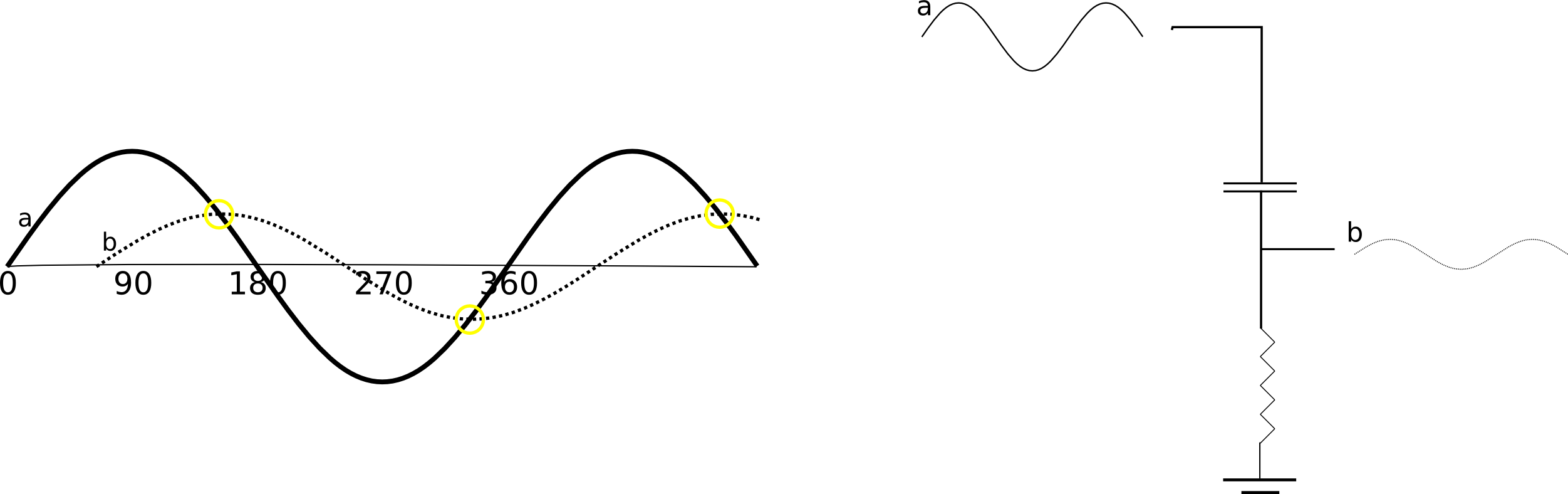
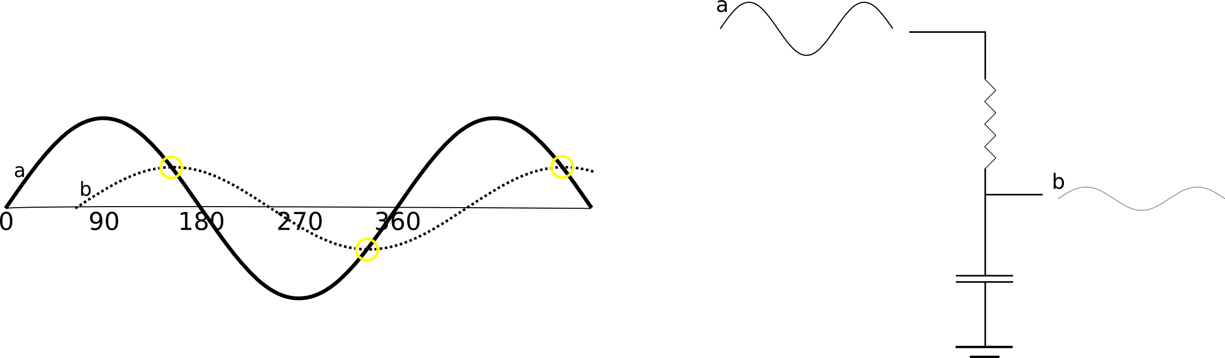
Today, I tried using the capacitors in a high pass configuration. To understand how this circuit works, we again need to understand how a capacitor in series will cause a voltage phase shift.

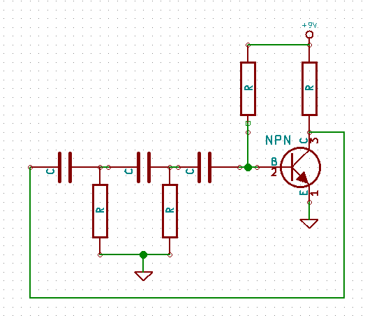
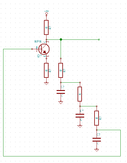
The diagram above shows the configuration used, and it’s surprisingly similar to that shown yesterday. However this time when a voltage build up on the top of our capacitor the capacitor will need to draw current though the lower resistor to equalize the voltage. This will take time, causing a delay, and therefore a phase-shift as before. As before the phase-shift is limited to 90degrees (and a larger shift causes more attenuation). The circuit below uses 3 such circuits to generate a 180degree phase-shift:

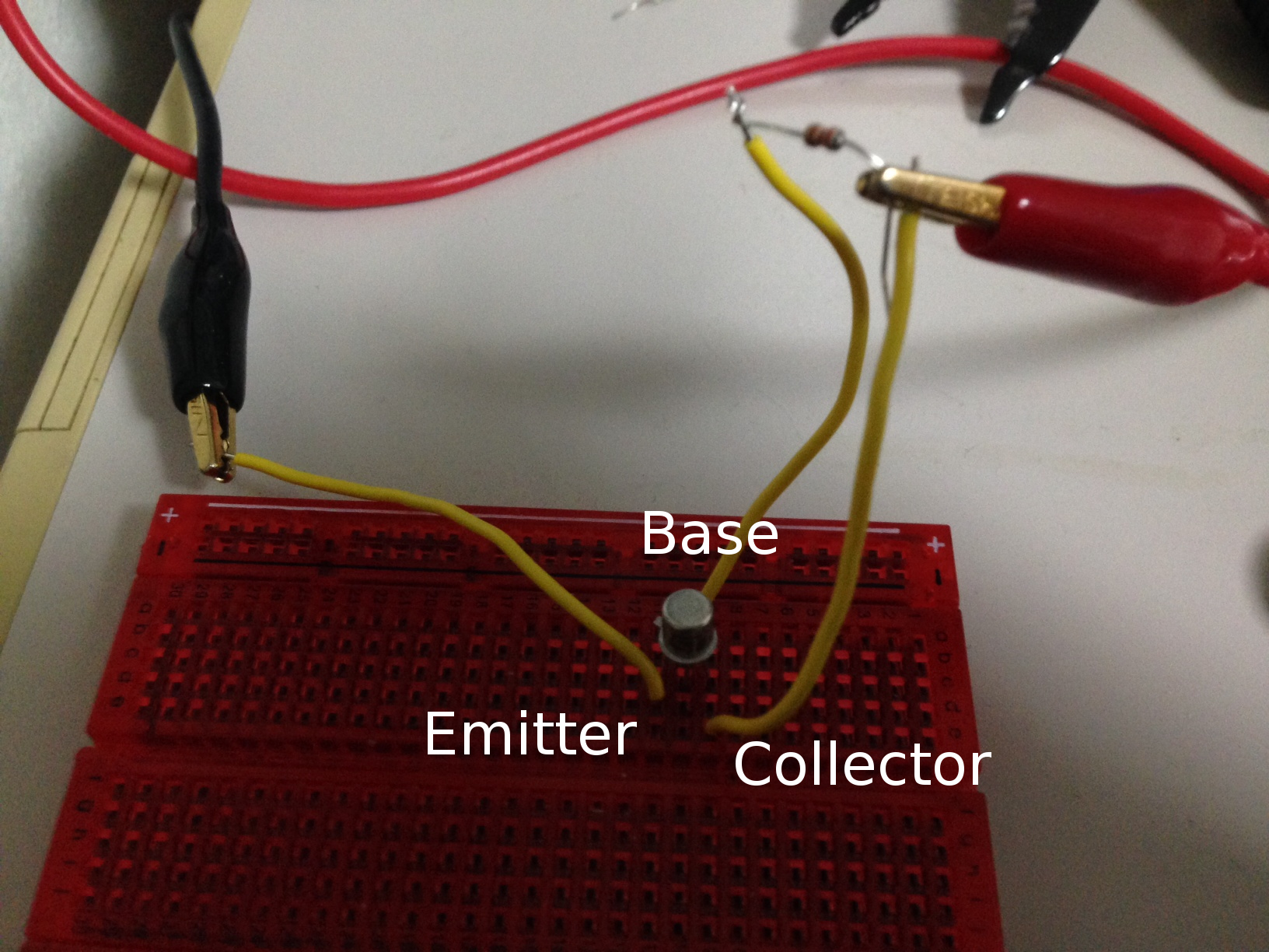
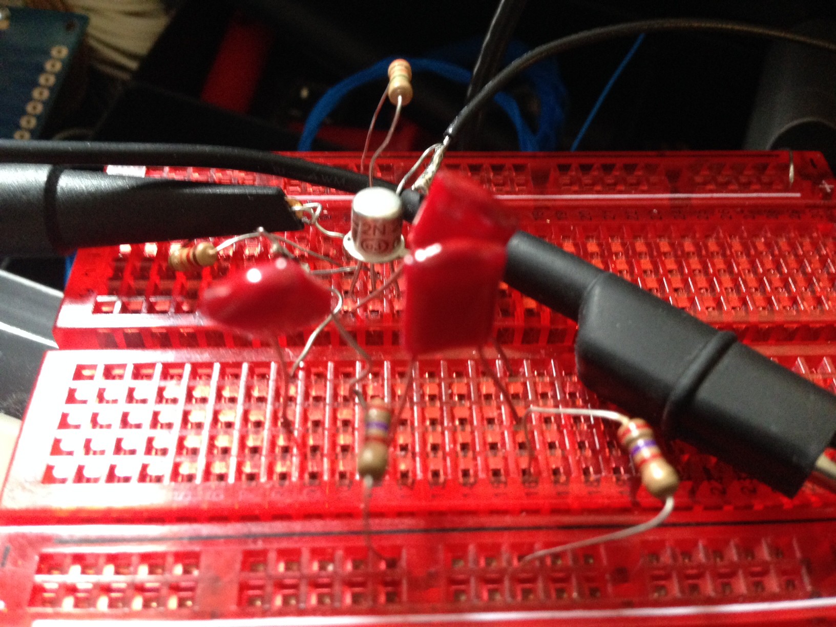
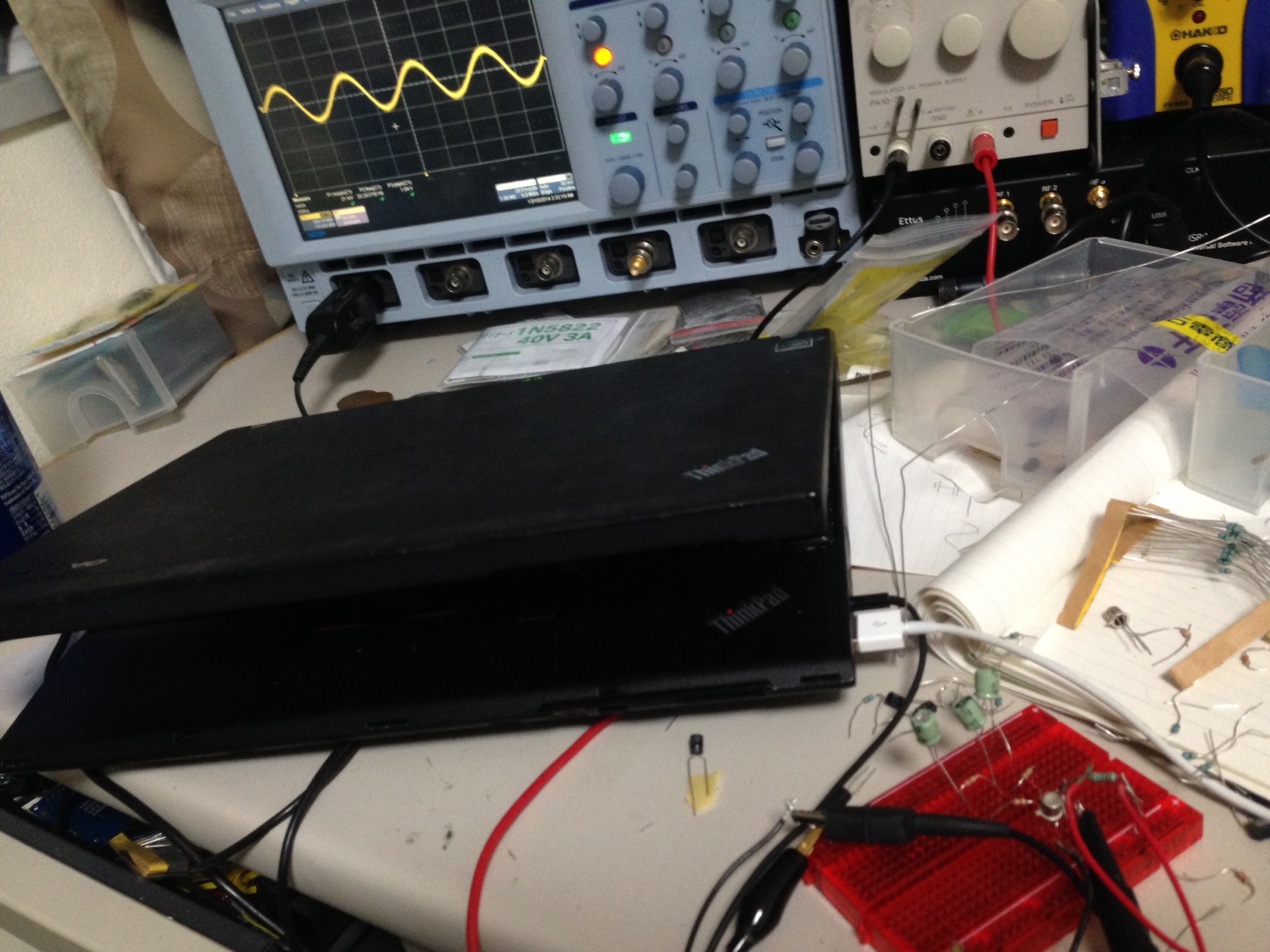
I built the above circuit using a 2N2222 (a 2N3904 works as well). I used 22nF capacitors. Unlike the previous example these can’t be electrolytic. The resistors on the caps were 2.7K. The resistor going from the supply to the emitter was 12k and from the base to the supply 600k.

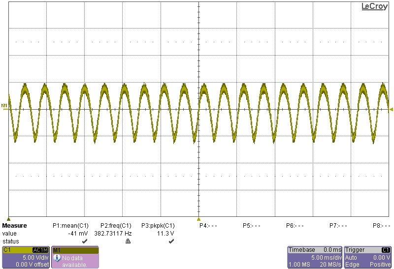
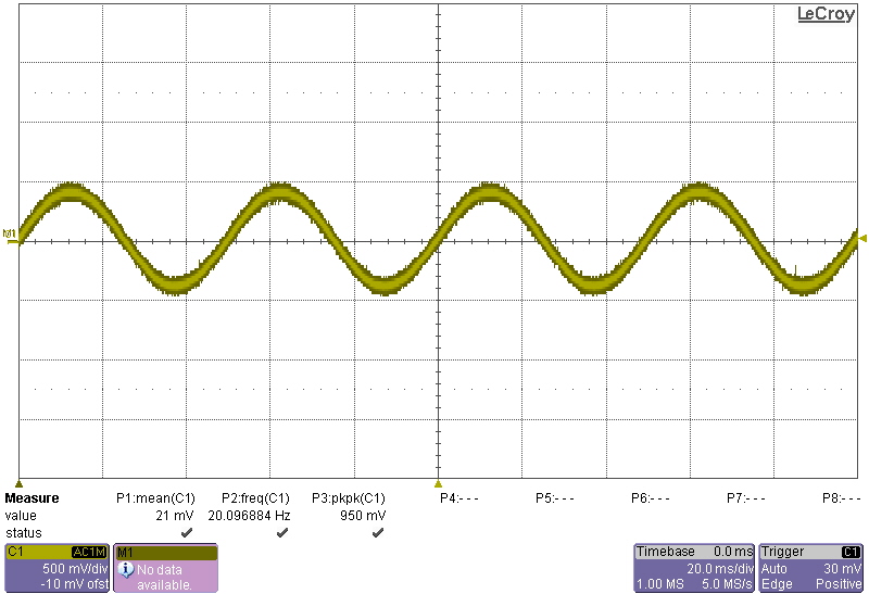
And here’s the output:

Category:
Uncategorized |
Comments Off on Phase Shift Oscillator – High Pass configuration
December 10, 2014, 3:03 am
Today I’ve been trying to understand the phase-shift oscillator. In order to understand the phase-shift oscillator, you first need to understand the phase-shift caused by a capacitor!
The figure below shows a single capacitor causing a phase shift:

It took me a little while to understand why a capacitor in this configuration causes a voltage phase shift. However, fundamentally the charging of the capacitor causes a lag, it take the capacitor a while to “catch up” with the current voltage, so it appears to lag behind the input. This means the amount shifted will depend on the capacity of the capacitor (how long it takes the capacitor to get up to full voltage). The capacitor can only lag behind the current voltage. This means that you can shift the phase by at most 90 degrees. Any more that this and the capacitor would be fighting the input voltage, rather than approaching it’s current value. The phase-shift will also always cause some attenuation, that the capacitor is trying to “catch up” with the current voltage, but never quit getting there. It’s worth note that if you overlay the original sine wave and the shifted version, the shifted wave will always cross the input at the shifted versions maximum voltage. You can therefore see the relationship between attenuation and the degree of phase-shift.
Hopefully that helps explain phase-shift a little. For a phase-shift oscillator we use this characteristic to generate an oscillation.
Here’s the phase-shift oscillator circuit, there are different configurations, but this is the one we’re going to talk about:

I’ve drawn the schematic so the 3 phase-shift resistor/capacitors line up. Each set will shift the phase of the input ~60 degrees. This results in a 180 degree shift. Remember because we can only shift by less than 90 at a time we need 3 sets of capacitors. We’ll also be significantly attenuating the input with each shift.

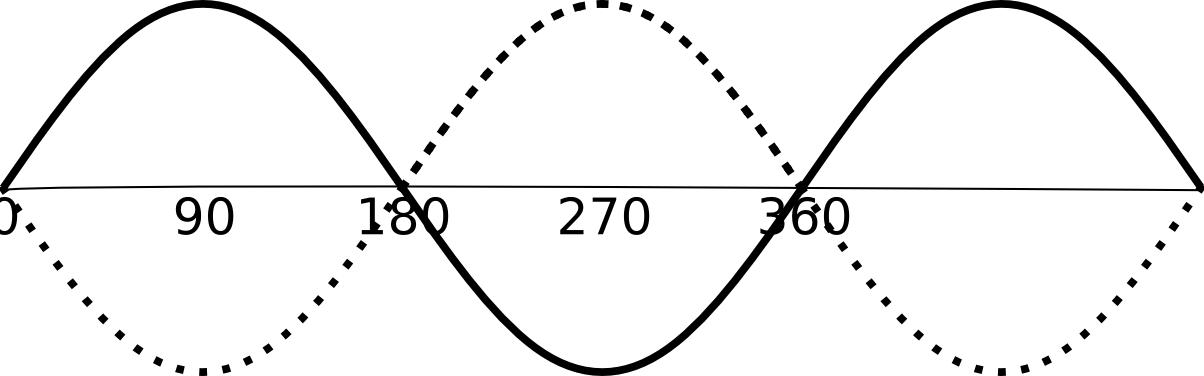
The output of the phase-shift network in this oscillators drives the input to an amplifier (in this case a transistor) in a feedback loop. But why do we want to shift by 180 degrees? Well, if we shift a sine wave by 180 degrees we’ll end up with the exact opposite of our signal. The NPN transistor we’re using is in an inverting configuration (you might want to read my other post about that), this effectively gives another 180degrees of shift. The result is a resonance at a frequency determined by the phase-shift network resulting in an oscillation.
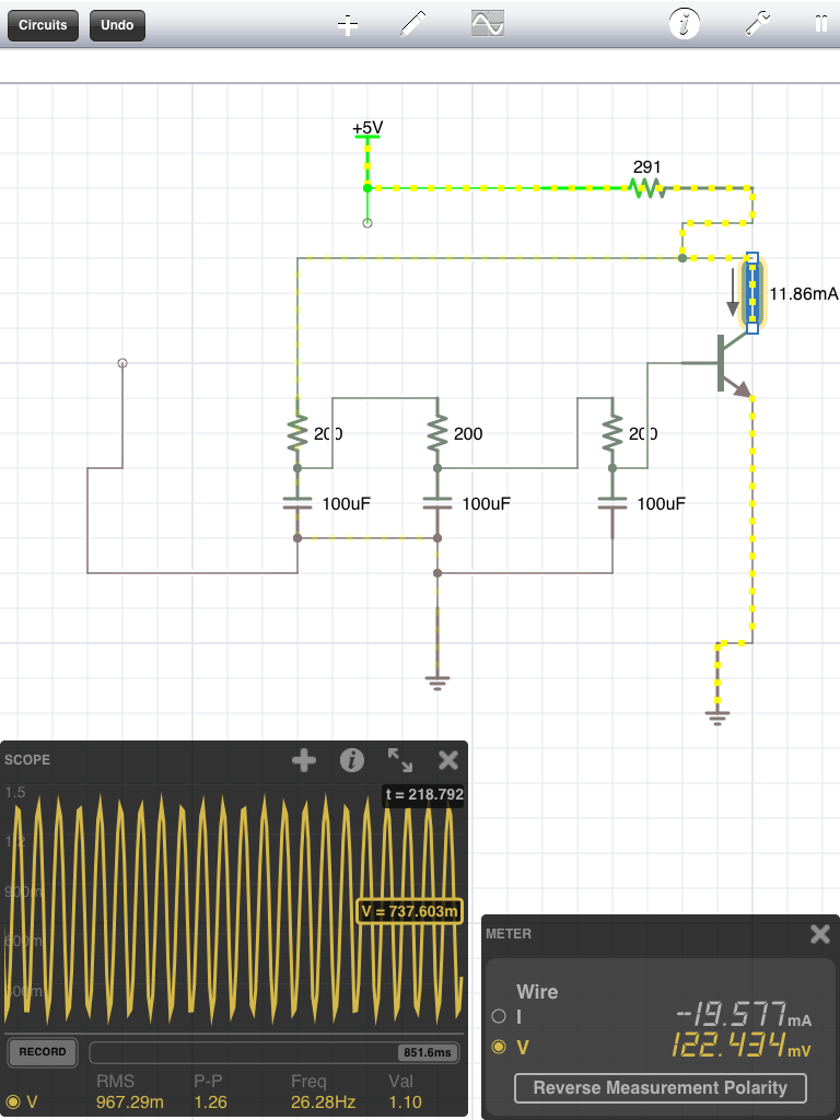
Here’s a simulation of the phase-shift circuit shown above:

You can also download the file for iCircuit here.
I built the circuit up using an 2N2222 and the approximate values in the simulation above:

It worked pretty well, output a 20Hz sine wave which is approximately as expected from the simulation:

Here’s a clearer picture of the trace:

December 8, 2014, 10:28 pm
I couldn’t find any dimension data on the Casio F91W (or module 593 which is used in it) online, and I’ve been wanting to use it for a project (replace the electronics with an MSP430 and my own display). Anyway, took some photos for my reference and am sticking them here in case they’re of use to anyone else!


December 8, 2014, 4:13 pm

After making a simple oscillator using a relay yesterday. I decided to move on to transistors today. This mirrors the technological development of oscillators. The original oscillators used in radio transmission were based on spark caps. A capacitor would charge for a DC supply until it built up enough potential to jump a spark gap allowing the current to discharge and the whole process to start again:

While I’ve seen referencing say they could reach MHz speeds with spark gaps (which surprises me!) it seems unlikely that they were particularly reliable, the resulting signal was obviously far from a clean sine wave. For this reason radio transmission oscillators migrated briefly to a more typical electromechanical approach, alternators!

The wikipedia page is hugely informative, and describes alternators producing frequencies up to a 100Khz! Some of which were still in operation in the 1950s.
However, their useful life was rather brief, as these oscillators were quickly replaced by active valve and transistors designs.
So today I decided to look at the Astable multivariator, a 2 transistor oscillator. Wikipedia provides the schematic below:

Which I put together using a 2N3904. I used a 100uF capacitor and 200Ohm and 1.2K resistors. This resulted in a frequency of ~6Hz. Which given the frequency determining equation derived on the wikipedia page of f=0.72/RC is approximately correct.

My basic understanding of the circuit is as follows. You can basically ignore R1 and R4, they simply limit the current going through the transistor, and into the capacitors (see note [1]). They are relatively small values (as compared with R2 and R3). When power is applied, one of Q1 or Q2 will be conducting more than the other. When the transistor conducts, it allows the capacitor on it’s base to charge up very quickly though that small resistor. This makes the other side of the capacitor negative with respect to ground (e.g. -5V if you’re using a 5V supply). This strong negative potential forces the other transistor open. The negative charge on the capacitor slowly discharges through the larger resistor (R2/R3), equalizing the charge on both sides of the capacitor. As this negative potential discharges, it rises above the transistors transition voltage and allows the other transistor to start conducting. It’s transistor now charges up very quickly, forcing a negative potential onto it’s other side, making the other transistor an open circuit and starting the process all over again.
Hopefully the following iCircuit spice simulation also makes things clear (you can download the iCircuit file here).
I also liked this video, it helped me a lot:
[1] This is probably a wrong interpretation, see my EEstackexchange question.
Category:
Uncategorized |
Comments Off on Astable multivibrator oscillator and a little oscillator history