NPN Common Collector, Colpitts oscillator notes

colpitts

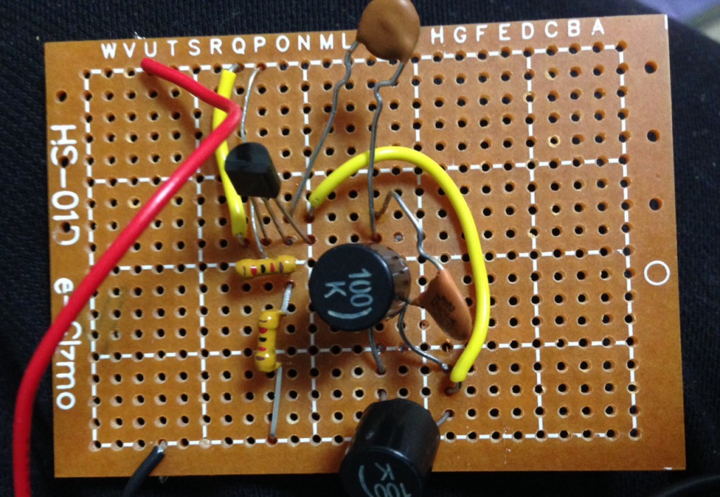
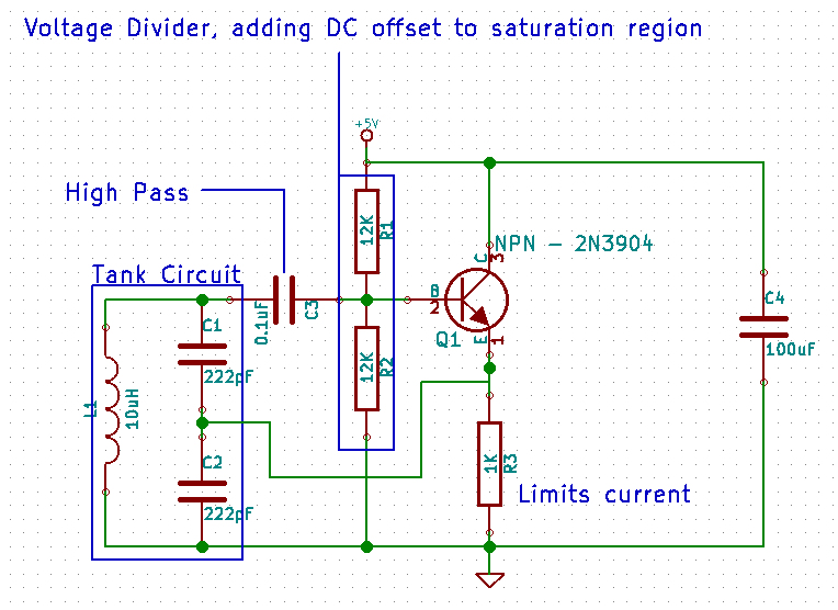
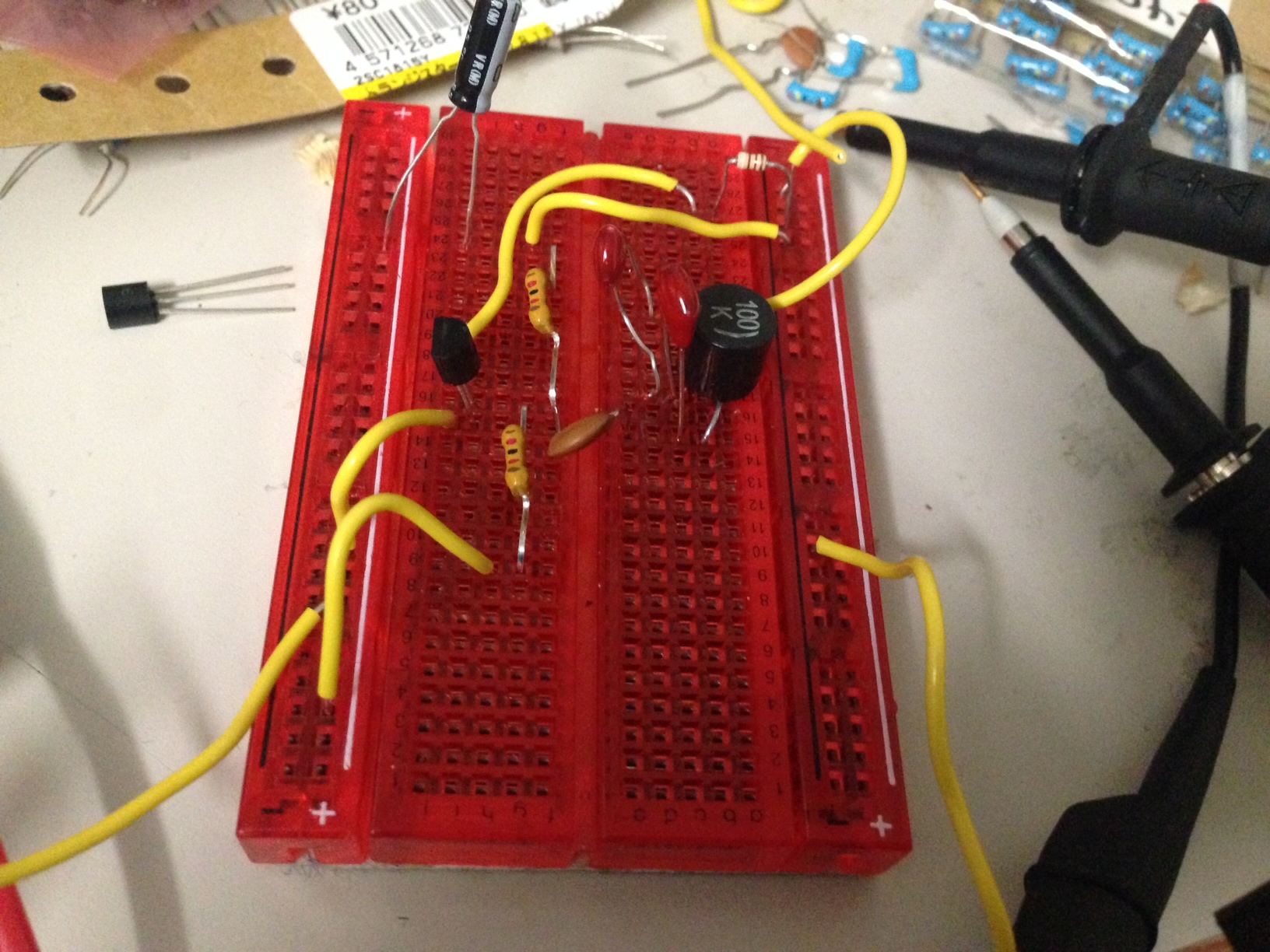
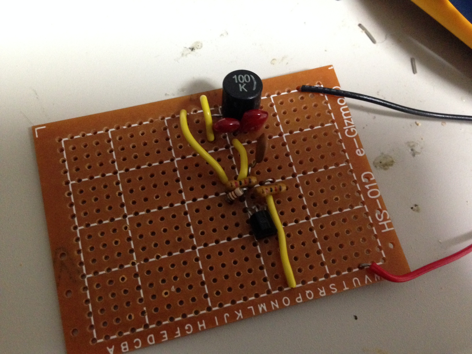
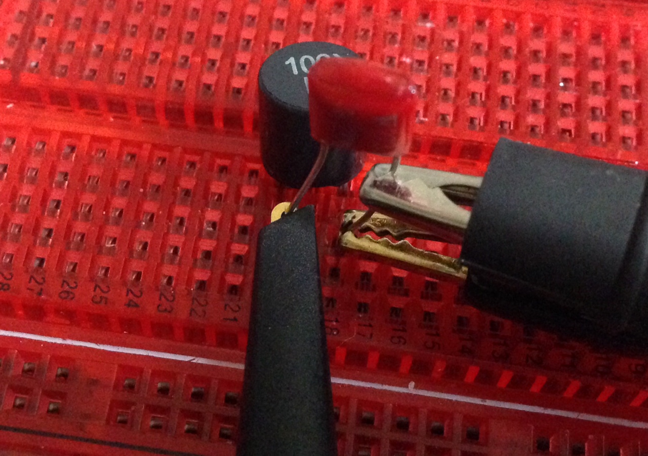
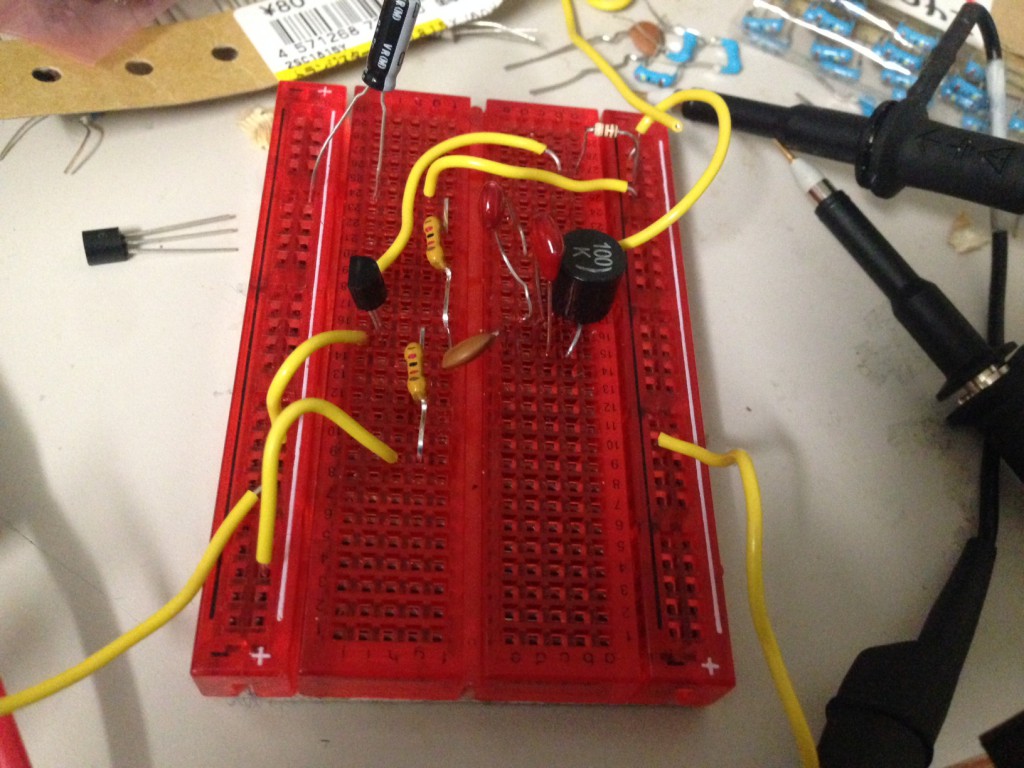
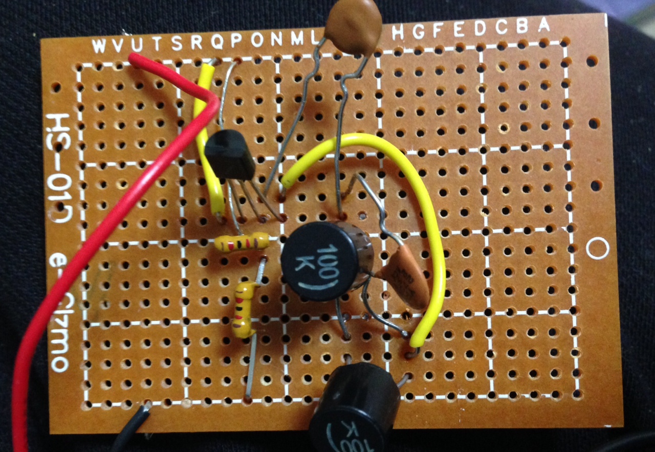
Today I built up a colpitts oscillator (shown above). The Colpitts oscillator is a tank (or LC network oscillator). It uses the resonance of an LC network which I looked at yesterday in a feedback loop to generate a oscillation.

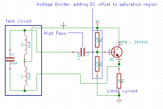
The circuit I used is shown above, I’ve annotated the function of the different parts of the circuit as I understand it.
colpitts

I’ve a lot more to learn to understand how this is working properly, but this is my vague understanding so far…
In terms of conventional current flow, when the circuit powers up, C1 and C2 are charged with a positive voltage at the point where they are connected to the emitter. As they charge, C1 pulls the base negative, reducing the current flow. The inductor also gets current pulled through it, inducing a magnetic field as it does so. The transistor will reduce the flow of current on out of the emitter as the current on the base decreases. Meaning C1 and C2 will being to discharge. As they do so, current will no longer flow through the inductor. The magnetic field will therefore collapse, the breakdown of the field again generates a current, but this time in the opposite direction. It charges C1 and therefore C2, resulting in a resonance. This resonance is maintained my the positive feedback from the transistor.

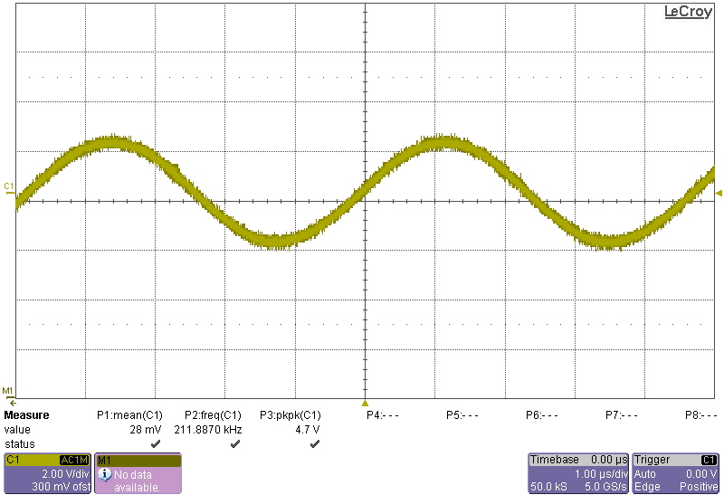
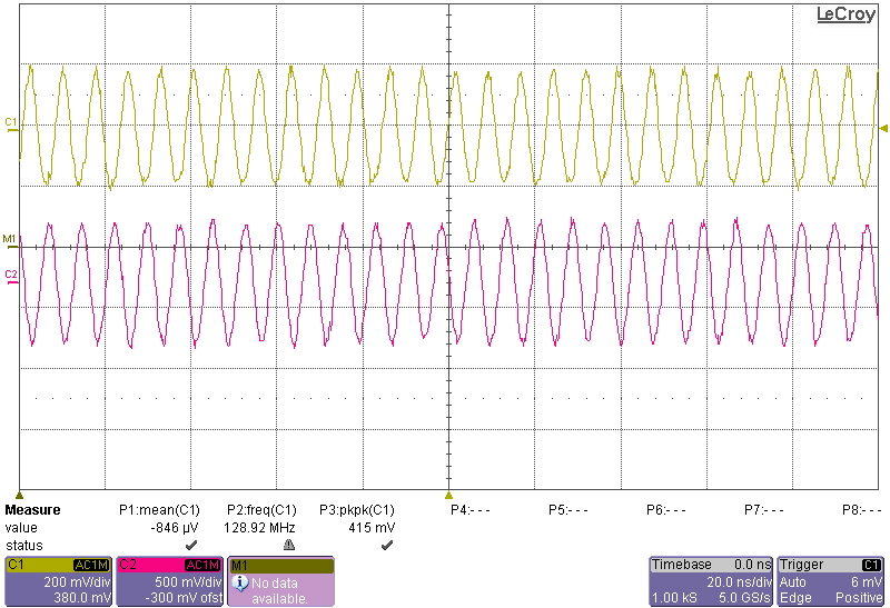
Here are some waveforms I recorded:
A11

[UPDATE]

After reviewing the circuit, I realized 2 things. 1) It should have been oscillating at 4MHz. 2) I’d omitted the feedback from the emitter to the tank!
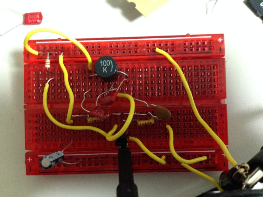
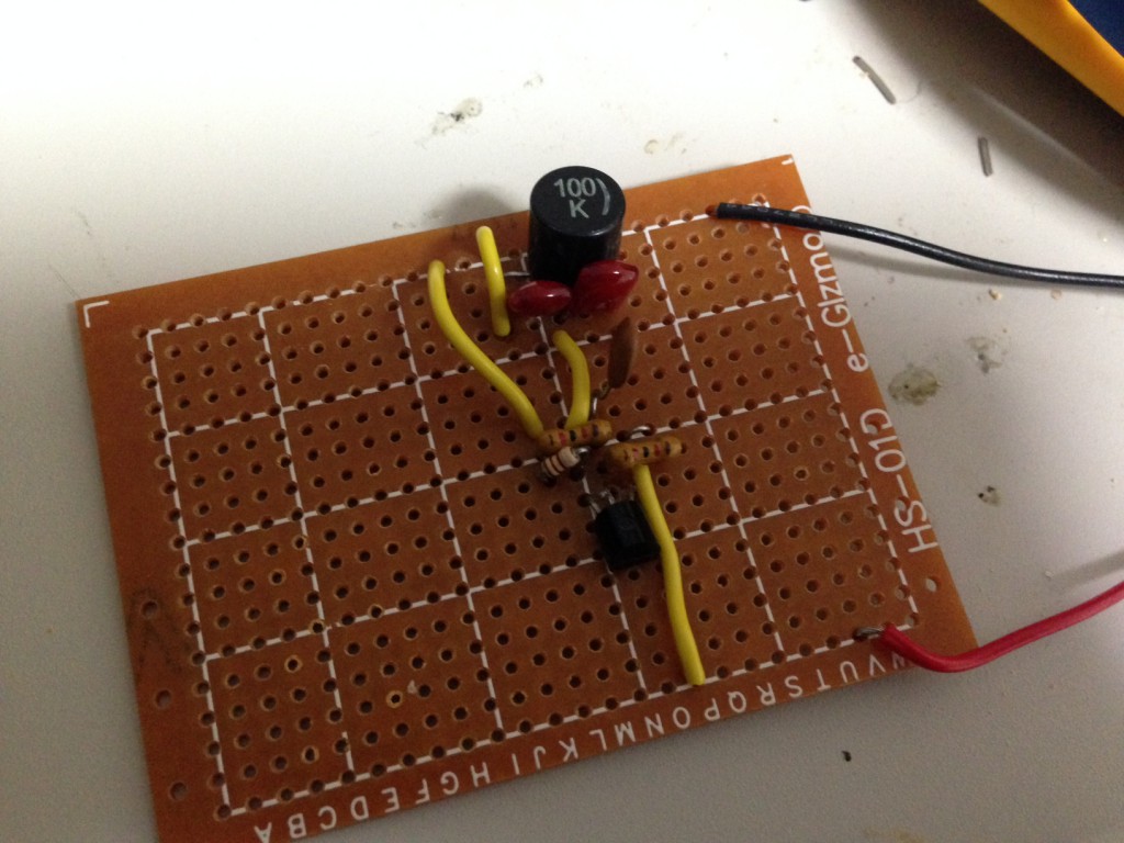
colpitts2_1

colpitts2_2

After fixing this the circuit correctly oscillated at 4MHz, I also no longer needed the decoupling capacitor! Here’s the new output waveform:
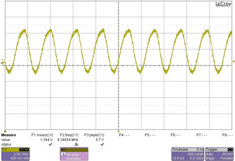
A12

Tank Circuits

In preparation for learning more about the Colpitts Oscillator, I wanted to understand Tank circuits a bit better. A Simple Tank (or LC) circuit is simple a Inductor and a capacitor in parallel:
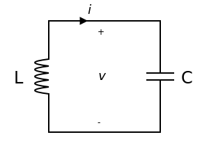
300px-LC_parallel_simple.svg

The tank circuit is useful because it results in a resonance. If you charge the capacitor and then remove power, the capacitor will discharge through the inductor. As the charge passes through the inductor it will build up a magnetic field, storing the energy. When the capacitor finishes discharging the field will collapse. This will result in a current, which will charge the other side of the capacitor, beginning the process again. The process will continue producing a frequency determined by the discharge rate of the capacitor and inductor. This frequency is given by the equation:

freq

Wikipedia has a great animation of the process, replicated here (and slowed down slightly):
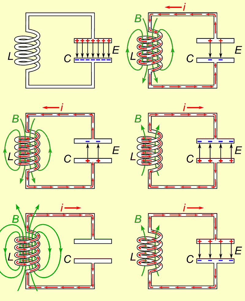
tank_slow

In a perfect world the resonance would keep going for ever, however losses due to the inductor resistance among other things means the resonance doesn’t last very long. You can see it on a scope however. To show this I connected a capacitor and inductor (22nF and 10uH) in parallel. The polarity will be reversing, so it’s likely unwise to use an electrolytic:
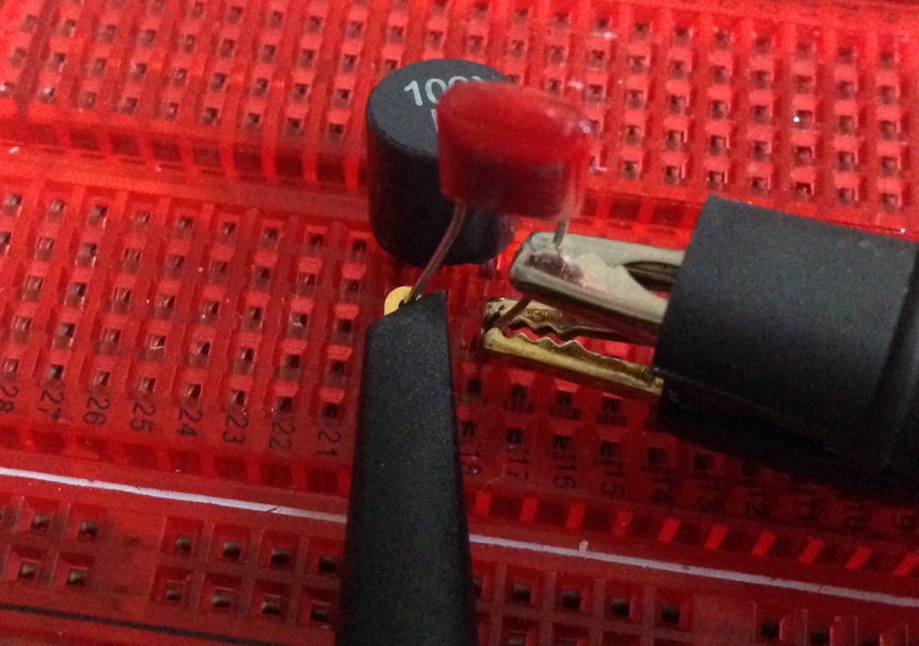
tank

I then connected the power and set my scope to take a single shot, then removed the power. The result was the following trace:
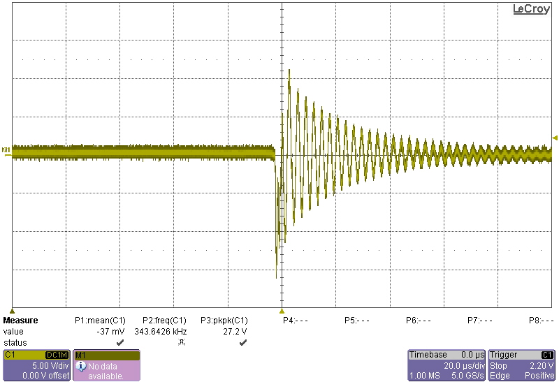
A6

Which as predicted by the equation above is ~340Khz.
NPN BJT Common emitter inverting amplifier

The Phase-Shift Oscillator I previously described used an NPN transistor as an inverting amplifier.

Transistors are current controller, current amplifiers. This means they take a control current in, and this is used to produce an output current. You’ll typically see curves like this used to describe the operation of a transistor:

Bipolar_Transistor_CharacteristicCurve

I find them pretty confusing as a first introduction to transistors. Most datasheets don’t seem to include these curves either. Here’s a simpler graph:

transistor_graph

Not a very complicated graph is it. X any Y are on the same scale, so what the graph is saying is that a small change in the base->emitter current, creates a large change is the collector to emitter current. Let’s try and understand that in terms of resistance:

NPNTransistor

One way of thinking about a Bipolar transistor is as a electrically controlled variable resistor. By controlling the base current, you can control the resistance between the collector and emitter. But you generally aren’t using a current to control things in a circuit. This poses some practical problems. Let’s look at a 2N2222. You can download the datasheet here.

We can connected this up as follows:

trans_bb1

The collector is connected to the positive supply, the emitter is connected to ground. No current will flow. I set the supply to 3 volts, and no current was being drawn.

So, let’s try connecting the base to the voltage source:

trans_bb2

BANG! This wont work, there’s a current limiting resistor on the collector. So the reason isn’t that all the current flows from the collector to the emitter. No, the connection between the base and the emitter is the problem. Bipolar transistors are current controlled, and there’s effectively no resistance from the base and the emitter (as an analogy). This means that if we connect the base directly to a voltage source it will draw as much current as it can and the transistor will pop under the load.

trans_bb3

The easiest way to limit the current supplied with a voltage source is with a resistor. I added a 220Ohm resistor to the base, over 3Volts (V=IR) this gives a base->emitter current of 0.01A. Note in the above circuit there’s no resistor on the collector. But the supply showed 460mA being drawn. From this we can calculate the “current gain”. 0.01A on the base = 0.46A on the collector. Which is a gain of 46. If we look at the datasheet:

2N2222gain

We can see that’s about right, at a Collector current (Ic) of 440mA and around 1 to 10V we’re looking at a gain of 40 to 50. These results will hold as you vary the supply voltage, however you can’t go below 0.6V. The datasheet tells you this here:

2N2222saturation

So now we’ve seen how a transistor works. We’ve also seen how a voltage can be used to control the current flowing through the device. We can think of this as a current controlled variable resistor.

Well, a voltage divider looks like this:

voltage_div

Voltage dividers let us create a smaller voltage from a larger one. The smaller R2, the smaller the output voltage will be. We can therefore replace R2 with a transistor and the control a large voltage with a smaller one:

trans_volt

There’s one caveat. As we increase Vin, more current will pass though the transistor from the collector to the emitter. We’re effectively decreasing the resistance, meaning Vout will also get smaller. This means we have an inverting amplifier. The larger the input voltage, the smaller the output voltage.

There are reasons we might often prefer this over a non-inverting configuration (replacing R1 with a transistor). The most significant being that as we saw above the transistor can’t operate below 0.6V. By working in an inverting configuration we can avoid that issue.

Simple example of SDL in Emscripten (generating graphics from C)

It’s pretty easy to get emscripten installed. And straight forward to compile existing SDL code a simple:

emcc mycode.c -o mycode.html

Will work. However there are a few things to watch out for when working with SDL. Firstly, Emscripten currently supports SDl1.2 I don’t believe there are any plans for SDL2 support. Secondly you may need to change your code slightly. I tried my previous SDL1.2 example and it compiled and sort of worked, but pretty much hung the browser. The issue is that Emscripten doesn’t like infinite loops. In fact the correct way to work in emscripten is register a callback for screen rendering with emscripten_set_main_loop. You can set the required number of frames per second or allow the browser to decide. To use this function you also need to include emscripten.h. Here’s a version of my previous code modified to use this callback:

#include <string.h>
#include <SDL/SDL.h>
#include <iostream>
#include <emscripten.h>

using namespace std;
 
SDL_Surface *screen;

void renderloop() {
  SDL_Flip(screen);
  SDL_LockSurface(screen);
  for(int n=0;n<1000;n++) {
    int x=rand()%800;
    int y=rand()%600;
    int pixel=rand()*100000;
    int bpp = screen->format->BytesPerPixel;
    Uint8 *p = (Uint8 *)screen->pixels + y * screen->pitch + x * bpp;
    if((x>screen->w)||(y>screen->h)||(x<0)||(y<0)) return;
    *(Uint32 *)p = pixel;
  }
 
  SDL_Event event;
  while(SDL_PollEvent(&event)) {
    if(event.key.keysym.sym == SDLK_c     ) { SDL_FillRect(screen,NULL,0); }
  }
 
  SDL_UnlockSurface(screen);
  //SDL_Quit();
}

int main(int argc, char *argv[]) {

 
  if(SDL_Init(SDL_INIT_VIDEO)<0) {
    cout << "Failed SDL_Init " << SDL_GetError() << endl;
    return 1;
  }
 
  screen=SDL_SetVideoMode(800,600,32,SDL_ANYFORMAT);
  if(screen==NULL) {
    cout << "Failed SDL_SetVideoMode: " << SDL_GetError() << endl;
    SDL_Quit();
    return 1;
  }
 
  emscripten_set_main_loop(renderloop,0,0);
 
  return 0;
}

You can compile it using the command above (assuming you save it as mycode.cpp). And you should see the following output in firefox:

emscripten_graphics