August 19, 2015, 12:32 am
This is the first rev of an LTC1859 Arduino shield. The LTC1859 is a nice little 8 channel SPI ADC. I laid the board out with SMA connectors, hopefully with ample spacing to connect them all. However for my application I only really need a couple so, I may end up leaving most of them unpopulated. Sending it out to fab now so we’ll see what revs are required!
LTC1859.tar
August 17, 2015, 4:57 pm
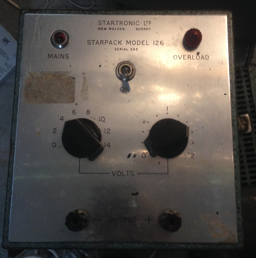
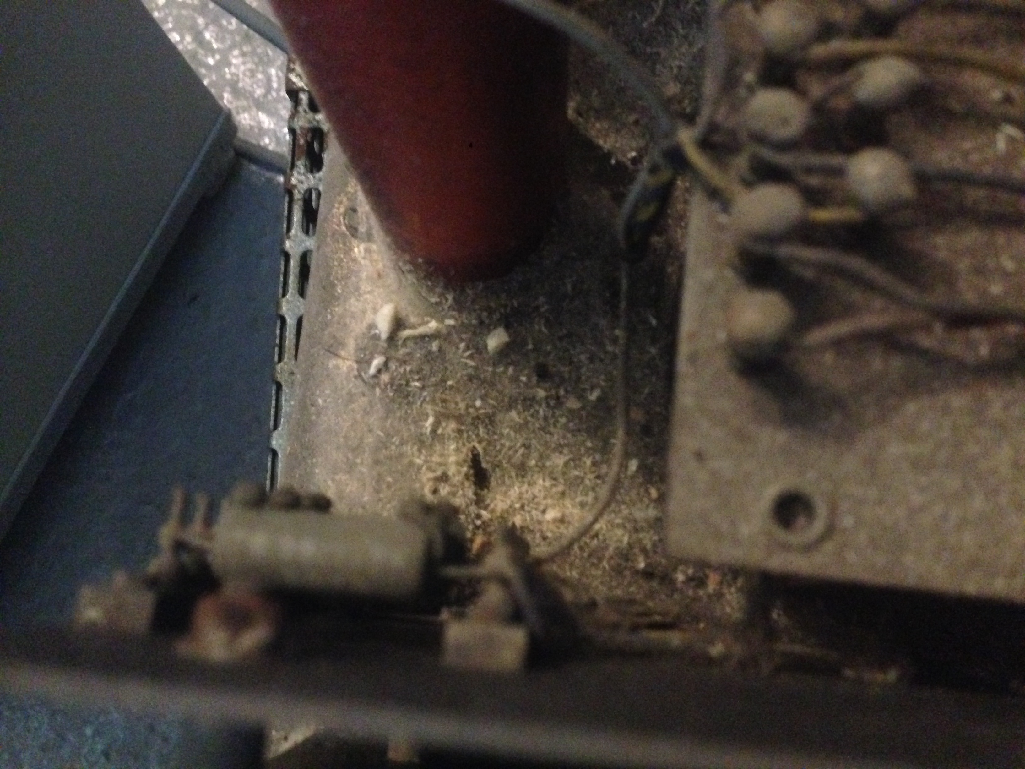
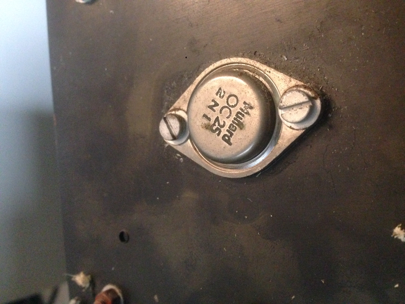
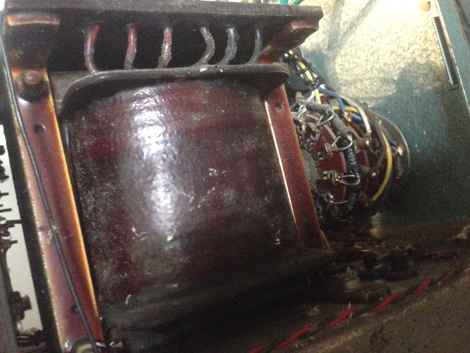
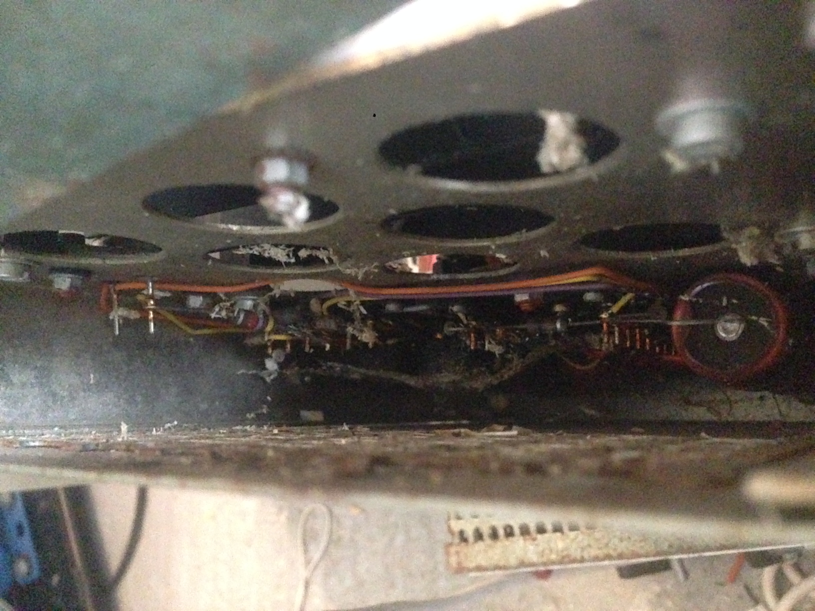
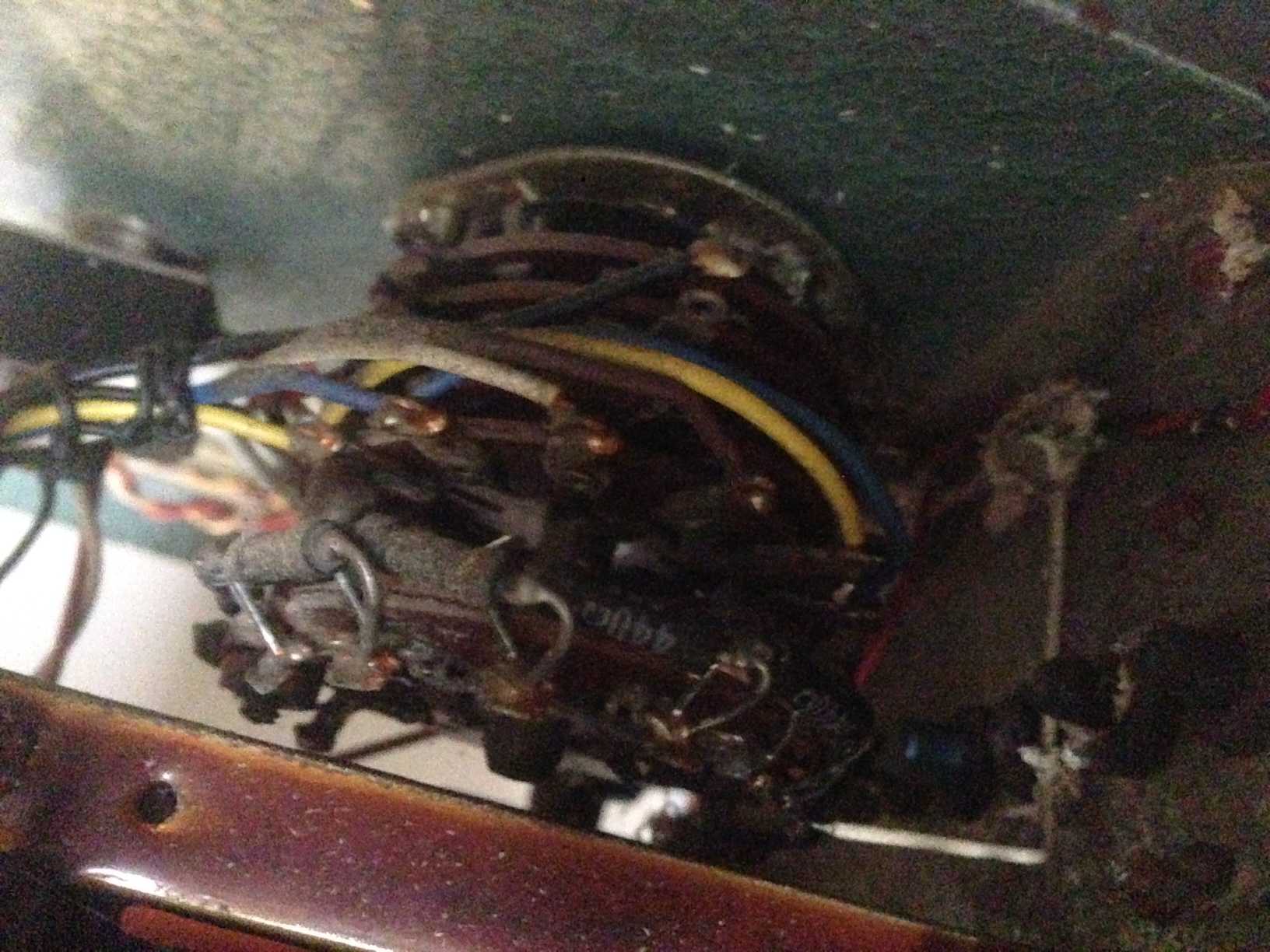
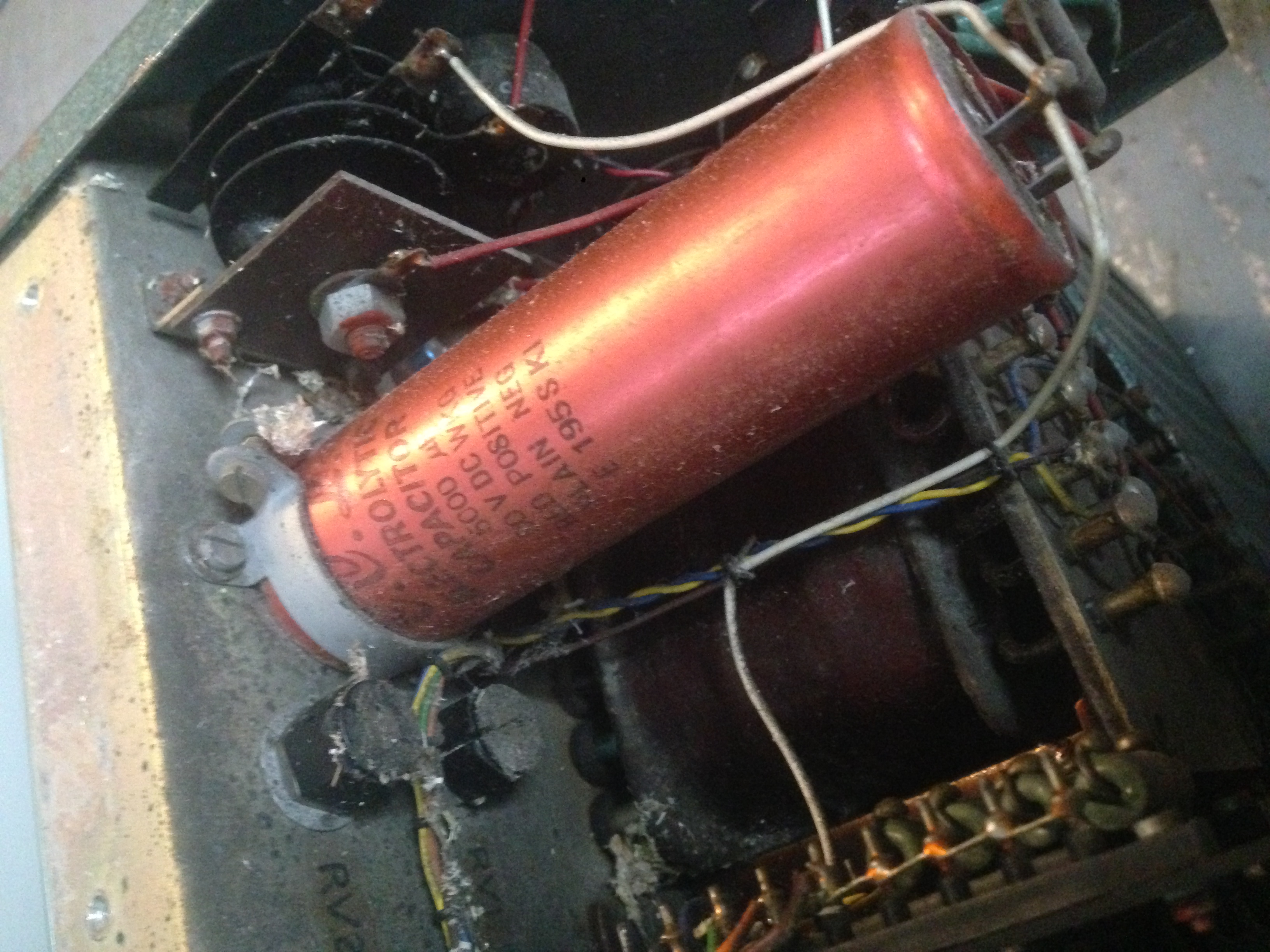
Misc picks of this ancient linear bench supply. I picked this up around 2005 from what was called “junk stores” at the University of Southampton. It was a non-profit shop which used to sell very old bits of university surplus. They knocked it down to make way for a fancy new lobby…
I got two of them and I think they cost one or two pounds each. I was very happy, and this was my go to power supply for a few years. I’d also picked up a pretty good analogue scope from the Chemistry department skip IIRC… Good times.
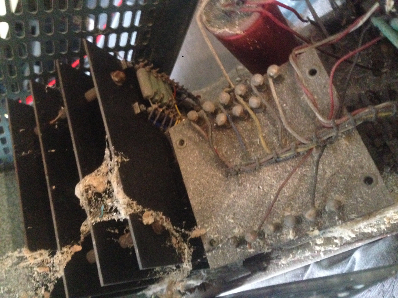
It’s been sitting in a damp shed for a few years now, but I decided to dig it out and see if it would be useful. It was a little dusty… 🙂
I’d guess the unit dates from the 50s or 60s. The transistors are Mullard brand, Mullard were a UK component manufacturer and I’d guess these transistors were even fabricated in the UK. They were eventually acquired by Phillips and the Fab stuff became part of NXP if Wikipedia can be believed. All those facilities have closed now it seems. Shame…
Still works, it’s about a volt out but can still drive pretty reasonable loads not bad considering it show no signs of calibration. Pretty impressive for a 50 year old instrument.
It’s probably of limited utility in a modern lab as it doesn’t have current limiting, but it may yet find a home.
August 17, 2015, 4:33 pm
The charger on my Wife’s Surface failed, it was a cheap eBay replacement so I wasn’t hugely surprised that it failed after 6 months. I ordered a replacement but to get things up and running again I decided to fiddle with the existing charger.
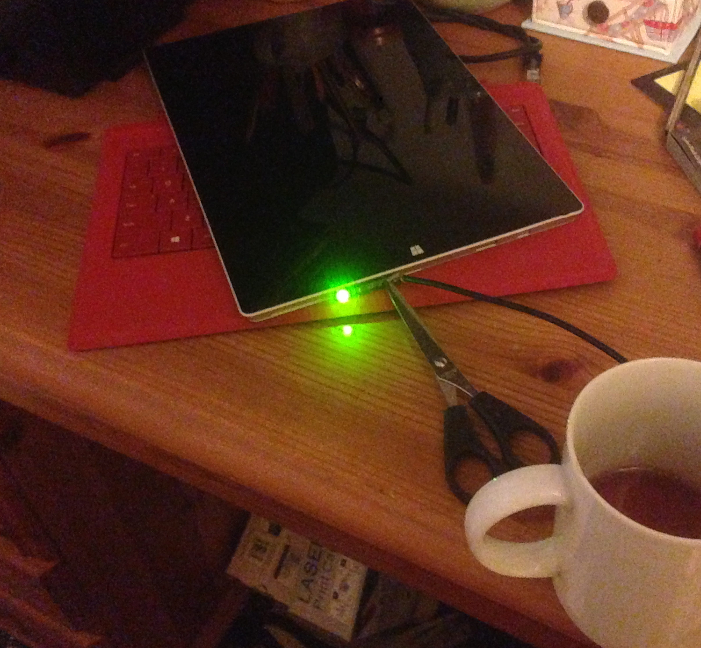
Here’s what I found when I removed the casing around the connector. The frayed cables had shorted and also blow the SMD fuse:
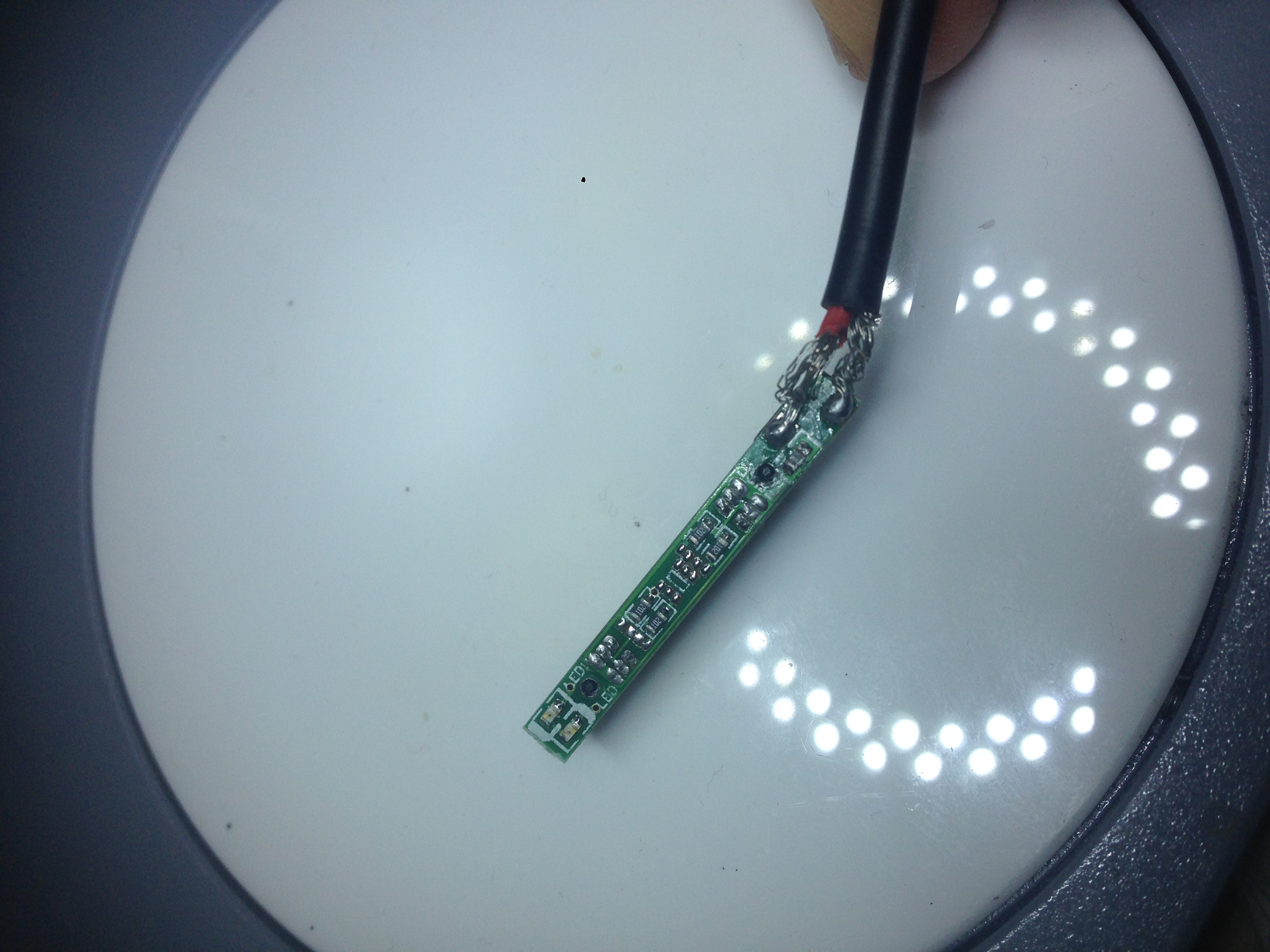
Here’s the temporary fix, I’m not proud. I was too lazy to make my way to a soldering iron and separating out the wires and shorting the fuse got the Surface charging and made my wife happy:
Here’s the medium term solution, re-soldered the wires. I’m not terribly happy with this but it’ll hold out until the new charger arrives. It seems like a poor design choice that the wires are just soldered to SMD pads not through-hole, and that the ground wire is unshielded (for the observant reader, yes the wires are opposite way round I flipped the polarity at the other end).
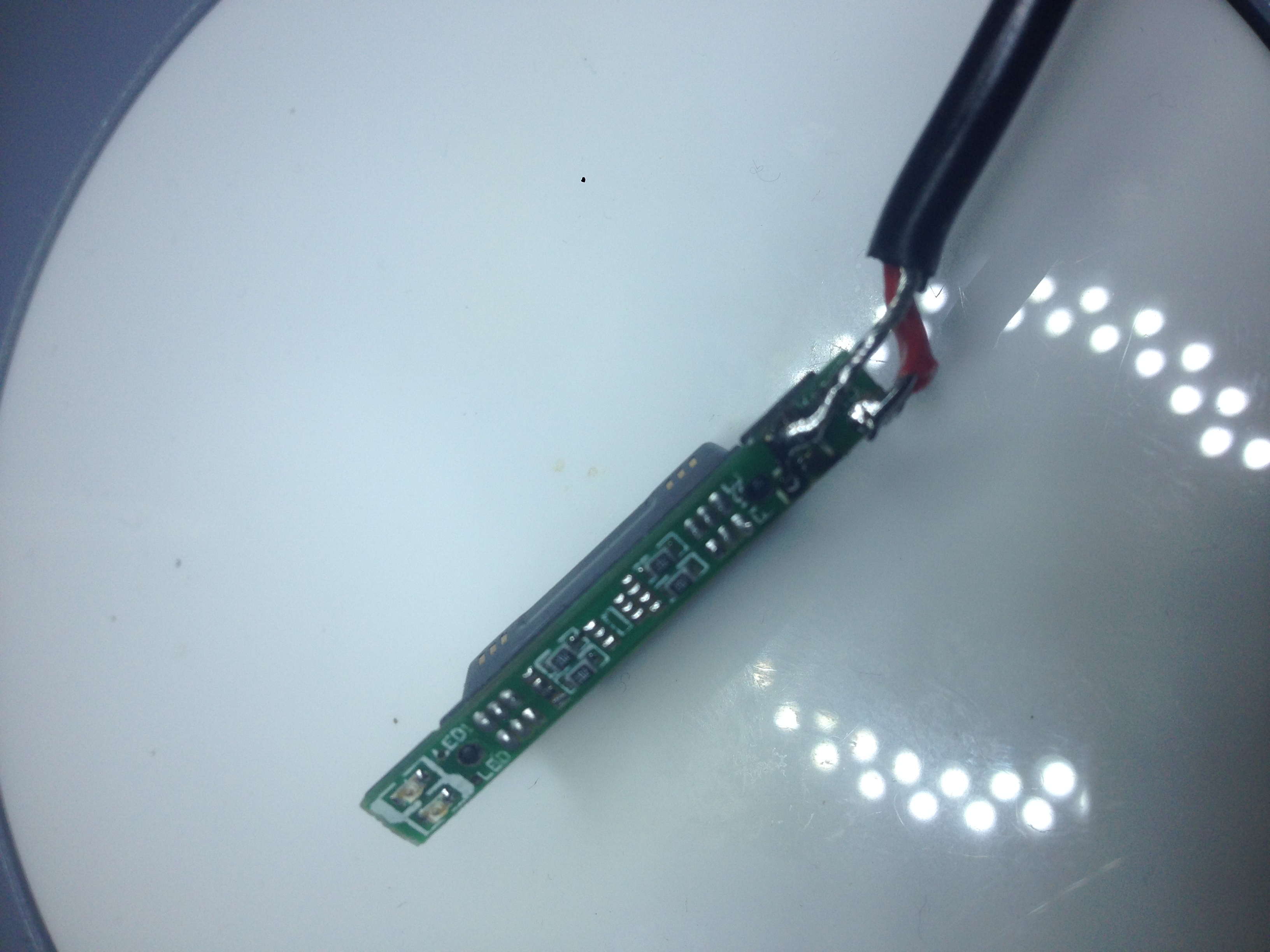
To provide some insulation I then stuck some heatshrink over the top, with a slit in it for the connector to poke out. That seemed to work reasonably well.
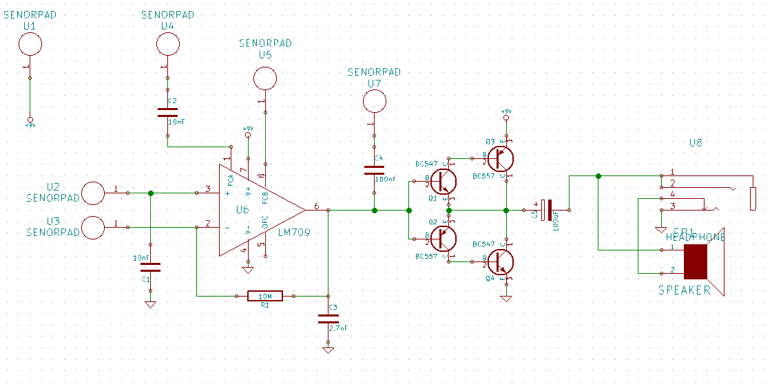
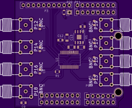
August 15, 2015, 9:26 pm
First trial layout of a Kraakdoos using the schematic from here. I’ll be sending this to fab shortly as a trial run. Lots to talk about in this circuit and updates should hopefully follow.
Kicad files and layout: kraakdoos