msp430f2013 I2C frustrations

display

UPDATE: See this post which shows how I finally got it working.

I’ve been trying to get a ST7032i based display working with a msp430f2013 on a EZ430-F2013. Unfortunately without much success. After hours of debugging I discovered that the glass on the display was fractured… guess I’ll be ordering some more.

Anyway, it did get as far as acknowledging my commands. And I found a working I2C sample. It was hidden pretty well on the TI site, I think in a zip called slac080l.zip. The file I was working from was msp430x20x3_usi_07.c. My hacked version is reproduced below, you can almost feel the frustration I’m sure (it’s an absolute mess). But it does work with the MSP430GCC compiler, and produce working I2C output.

/* --COPYRIGHT--,BSD_EX
 * Copyright (c) 2012, Texas Instruments Incorporated
 * All rights reserved.
 *
 * Redistribution and use in source and binary forms, with or without
 * modification, are permitted provided that the following conditions
 * are met:
 *
 * *  Redistributions of source code must retain the above copyright
 *    notice, this list of conditions and the following disclaimer.
 *
 * *  Redistributions in binary form must reproduce the above copyright
 *    notice, this list of conditions and the following disclaimer in the
 *    documentation and/or other materials provided with the distribution.
 *
 * *  Neither the name of Texas Instruments Incorporated nor the names of
 *    its contributors may be used to endorse or promote products derived
 *    from this software without specific prior written permission.
 *
 * THIS SOFTWARE IS PROVIDED BY THE COPYRIGHT HOLDERS AND CONTRIBUTORS "AS IS"
 * AND ANY EXPRESS OR IMPLIED WARRANTIES, INCLUDING, BUT NOT LIMITED TO,
 * THE IMPLIED WARRANTIES OF MERCHANTABILITY AND FITNESS FOR A PARTICULAR
 * PURPOSE ARE DISCLAIMED. IN NO EVENT SHALL THE COPYRIGHT OWNER OR
 * CONTRIBUTORS BE LIABLE FOR ANY DIRECT, INDIRECT, INCIDENTAL, SPECIAL,
 * EXEMPLARY, OR CONSEQUENTIAL DAMAGES (INCLUDING, BUT NOT LIMITED TO,
 * PROCUREMENT OF SUBSTITUTE GOODS OR SERVICES; LOSS OF USE, DATA, OR PROFITS;
 * OR BUSINESS INTERRUPTION) HOWEVER CAUSED AND ON ANY THEORY OF LIABILITY,
 * WHETHER IN CONTRACT, STRICT LIABILITY, OR TORT (INCLUDING NEGLIGENCE OR
 * OTHERWISE) ARISING IN ANY WAY OUT OF THE USE OF THIS SOFTWARE,
 * EVEN IF ADVISED OF THE POSSIBILITY OF SUCH DAMAGE.
 *
 *******************************************************************************
 * 
 *                       MSP430 CODE EXAMPLE DISCLAIMER
 *
 * MSP430 code examples are self-contained low-level programs that typically
 * demonstrate a single peripheral function or device feature in a highly
 * concise manner. For this the code may rely on the device's power-on default
 * register values and settings such as the clock configuration and care must
 * be taken when combining code from several examples to avoid potential side
 * effects. Also see www.ti.com/grace for a GUI- and www.ti.com/msp430ware
 * for an API functional library-approach to peripheral configuration.
 *
 * --/COPYRIGHT--*/
//******************************************************************************
//  MSP430F20xx Demo - I2C Master Transmitter, single byte
//
//  Description: I2C Master communicates with I2C Slave using
//  the USI. Master data is sent and increments from 0x00 with each transmitted
//  byte which is verified by the slave.
//  LED off for address or data Ack; LED on for address or data NAck.
//  ACLK = n/a, MCLK = SMCLK = Calibrated 1MHz
//
//  ***THIS IS THE MASTER CODE***
//
//                  Slave                      Master
//          (msp430x20x3_usi_08.c)
//               MSP430F20x2/3              MSP430F20x2/3
//             -----------------          -----------------
//         /|\|              XIN|-    /|\|              XIN|-
//          | |                 |      | |                 |
//          --|RST          XOUT|-     --|RST          XOUT|-
//            |                 |        |                 |
//      LED <-|P1.0             |        |                 |
//            |                 |        |             P1.0|-> LED
//            |         SDA/P1.7|<-------|P1.7/SDA         |
//            |         SCL/P1.6|<-------|P1.6/SCL         |
//
//  Note: internal pull-ups are used in this example for SDA & SCL
//
//  Z. Albus
//  Texas Instruments Inc.
//  May 2006
//  Built with CCE Version: 3.2.0 and IAR Embedded Workbench Version: 3.41A
//******************************************************************************
#include <msp430.h>


// commands
#define LCD_CLEARDISPLAY 0x01
#define LCD_RETURNHOME 0x02
#define LCD_ENTRYMODESET 0x04
#define LCD_DISPLAYCONTROL 0x08
#define LCD_CURSORSHIFT 0x10
#define LCD_FUNCTIONSET 0x20
#define LCD_SETCGRAMADDR 0x40
#define LCD_SETDDRAMADDR 0x80
#define LCD_EX_SETBIASOSC 0x10 // Bias selection / Internal OSC frequency adjust
#define LCD_EX_SETICONRAMADDR 0x40 // Set ICON RAM address
#define LCD_EX_POWICONCONTRASTH 0x50 // Power / ICON control / Contrast set(high byte)
#define LCD_EX_FOLLOWERCONTROL 0x60 // Follower control
#define LCD_EX_CONTRASTSETL 0x70 // Contrast set(low byte)
// flags for display entry mode
#define LCD_ENTRYRIGHT 0x00
#define LCD_ENTRYLEFT 0x02
#define LCD_ENTRYSHIFTINCREMENT 0x01
#define LCD_ENTRYSHIFTDECREMENT 0x00
// flags for display on/off control
#define LCD_DISPLAYON 0x04
#define LCD_DISPLAYOFF 0x00
#define LCD_CURSORON 0x02
#define LCD_CURSOROFF 0x00
#define LCD_BLINKON 0x01
#define LCD_BLINKOFF 0x00
// flags for display/cursor shift
#define LCD_DISPLAYMOVE 0x08
#define LCD_CURSORMOVE 0x00
#define LCD_MOVERIGHT 0x04
#define LCD_MOVELEFT 0x00
// flags for function set
#define LCD_8BITMODE 0x10
#define LCD_4BITMODE 0x00
#define LCD_2LINE 0x08
#define LCD_1LINE 0x00
#define LCD_5x10DOTS 0x04
#define LCD_5x8DOTS 0x00
#define LCD_EX_INSTRUCTION 0x01 // IS: instruction table select
// flags for Bias selection
#define LCD_BIAS_1_4 0x08 // bias will be 1/4
#define LCD_BIAS_1_5 0x00 // bias will be 1/5
// flags Power / ICON control / Contrast set(high byte)
#define LCD_ICON_ON 0x08 // ICON display on
#define LCD_ICON_OFF 0x00 // ICON display off
#define LCD_BOOST_ON 0x04 // booster circuit is turn on
#define LCD_BOOST_OFF 0x00 // booster circuit is turn off
#define LCD_OSC_122HZ 0x00 // [email protected]
#define LCD_OSC_131HZ 0x01 // [email protected]
#define LCD_OSC_144HZ 0x02 // [email protected]
#define LCD_OSC_161HZ 0x03 // [email protected]
#define LCD_OSC_183HZ 0x04 // [email protected]
#define LCD_OSC_221HZ 0x05 // [email protected]
#define LCD_OSC_274HZ 0x06 // [email protected]
#define LCD_OSC_347HZ 0x07 // [email protected]
// flags Follower control
#define LCD_FOLLOWER_ON 0x08 // internal follower circuit is turn on
#define LCD_FOLLOWER_OFF 0x00 // internal follower circuit is turn off
#define LCD_RAB_1_00 0x00 // 1+(Rb/Ra)=1.00
#define LCD_RAB_1_25 0x01 // 1+(Rb/Ra)=1.25
#define LCD_RAB_1_50 0x02 // 1+(Rb/Ra)=1.50
#define LCD_RAB_1_80 0x03 // 1+(Rb/Ra)=1.80
#define LCD_RAB_2_00 0x04 // 1+(Rb/Ra)=2.00
#define LCD_RAB_2_50 0x05 // 1+(Rb/Ra)=2.50
#define LCD_RAB_3_00 0x06 // 1+(Rb/Ra)=3.00
#define LCD_RAB_3_75 0x07 // 1+(Rb/Ra)=3.75


char MST_Data = 0x40;                     // Variable for transmitted data
char SLV_Addr = 0x7C;                  // Address is 0x48 << 1 bit + 0 for Write
int I2C_State = 0;                     // State variable

int main(void)
{
  volatile unsigned int i;             // Use volatile to prevent removal

  WDTCTL = WDTPW + WDTHOLD;            // Stop watchdog
                __delay_cycles(250000);
  if (CALBC1_1MHZ==0xFF)			   // If calibration constants erased
  {											
    while(1);                          // do not load, trap CPU!!	
  }
  DCOCTL = 0;                               // Select lowest DCOx and MODx settings
  BCSCTL1 = CALBC1_1MHZ;               // Set DCO
  DCOCTL = CALDCO_1MHZ;

  P1OUT = 0xC0;                        // P1.6 & P1.7 Pullups, others to 0
  P1REN |= 0xC0;                       // P1.6 & P1.7 Pullups
  P1DIR = 0xFF;                        // Unused pins as outputs
  P2OUT = 0;
  P2DIR = 0xFF;

  USICTL0 = USIPE6+USIPE7+USIMST+USISWRST; // Port & USI mode setup
  USICTL1 = USII2C+USIIE;              // Enable I2C mode & USI interrupt
  USICKCTL = USIDIV_3+USISSEL_2+USICKPL; // Setup USI clocks: SCL = SMCLK/8 (~125kHz) // was USIDIV_3
  USICNT |= USIIFGCC;                  // Disable automatic clear control
  USICTL0 &= ~USISWRST;                // Enable USI
  USICTL1 &= ~USIIFG;                  // Clear pending flag
  __enable_interrupt();

  int a=0;
  for(int n=0;;n++)
  {
    if(n==0) MST_Data = 0x00;
    if(n==1) MST_Data = LCD_EX_SETBIASOSC | LCD_BIAS_1_5 | LCD_OSC_183HZ;
    if(n==2) MST_Data = 0x00;
    if(n==3) MST_Data = LCD_EX_FOLLOWERCONTROL | LCD_FOLLOWER_ON | LCD_RAB_2_00;
    if(n==4) MST_Data = 0x00;
    if(n==5) MST_Data = LCD_DISPLAYON | LCD_CURSORON | LCD_BLINKON;
    if(n==6) MST_Data = 0x00;
    if(n==7) MST_Data = LCD_ENTRYMODESET | LCD_ENTRYLEFT;

    if(n==9) MST_Data = 0x00;
    if(n==10) MST_Data = LCD_EX_CONTRASTSETL | (0x0c & 0x0f);
    if(n==11) MST_Data = 0x00;
    if(n==12) MST_Data = LCD_EX_POWICONCONTRASTH | LCD_ICON_ON | LCD_BOOST_ON | ((0x0c >> 4) & 0x03);
    if(n==14) MST_Data = 0x00;
    if(n==15) MST_Data = LCD_CLEARDISPLAY;
    if(n==16) MST_Data = 0x00;
    if(n==17) MST_Data = 0x40;
    if(n==18) MST_Data = 'a'+a;
    USICTL1 |= USIIFG;                 // Set flag and start communication
    LPM0;                              // CPU off, await USI interrupt
   // __no_operation();                  // Used for IAR
//    for (i = 0; i < 5000; i++);        // Dummy delay between communication cycles
    P1OUT &= ~0x01;           // LED off
    __delay_cycles(500000);
    if(n==18)n=16;
    a++;
  }
}

/******************************************************
// USI interrupt service routine
******************************************************/
#if defined(__TI_COMPILER_VERSION__) || defined(__IAR_SYSTEMS_ICC__)
#pragma vector = USI_VECTOR
__interrupt void USI_TXRX (void)
#elif defined(__GNUC__)
void __attribute__ ((interrupt(USI_VECTOR))) USI_TXRX (void)
#else
#error Compiler not supported!
#endif
{
  switch(I2C_State)
    {
      case 0: // Generate Start Condition & send address to slave
              P1OUT &= ~0x01;           // LED off
              USISRL = 0x00;           // Generate Start Condition...
              USICTL0 |= USIGE+USIOE;
              USICTL0 &= ~USIGE;
              USISRL = SLV_Addr;       // ... and transmit address, R/W = 0
              USICNT = (USICNT & 0xE0) + 0x08; // Bit counter = 8, TX Address
              I2C_State = 2;           // Go to next state: receive address (N)Ack
              break;

      case 2: // Receive Address Ack/Nack bit
              USICTL0 &= ~USIOE;       // SDA = input
              USICNT |= 0x01;          // Bit counter = 1, receive (N)Ack bit
              I2C_State = 4;           // Go to next state: check (N)Ack
              break;

      case 4: // Process Address Ack/Nack & handle data TX
              USICTL0 |= USIOE;        // SDA = output
              if (USISRL & 0x01)       // If Nack received...
              { // Send stop...
                USISRL = 0x00;
                USICNT |=  0x01;       // Bit counter = 1, SCL high, SDA low
                I2C_State = 10;        // Go to next state: generate Stop
              //  P1OUT |= 0x01;         // Turn on LED: error
                P1OUT |= 0x01;         // Turn on LED: error
                __delay_cycles(5000000);
              }
              else
              { // Ack received, TX data to slave...
                USISRL = MST_Data;     // Load data byte
                USICNT |=  0x08;       // Bit counter = 8, start TX
                I2C_State = 6;         // Go to next state: receive data (N)Ack
                P1OUT &= ~0x01;        // Turn off LED
              }
              break;

      case 6: // Receive Data Ack/Nack bit
              USICTL0 &= ~USIOE;       // SDA = input
              USICNT |= 0x01;          // Bit counter = 1, receive (N)Ack bit
              I2C_State = 8;           // Go to next state: check (N)Ack
              break;

      case 8: // Process Data Ack/Nack & send Stop
              USICTL0 |= USIOE;
              if (USISRL & 0x01)       // If Nack received...
              ;//  P1OUT |= 0x01;         // Turn on LED: error
              else                     // Ack received
              {
                MST_Data++;            // Increment Master data
              //  P1OUT &= ~0x01;        // Turn off LED
              }
              // Send stop...
              USISRL = 0x00;
              USICNT |=  0x01;         // Bit counter = 1, SCL high, SDA low
              I2C_State = 10;          // Go to next state: generate Stop
              break;

      case 10:// Generate Stop Condition
              USISRL = 0x0FF;          // USISRL = 1 to release SDA
              USICTL0 |= USIGE;        // Transparent latch enabled
              USICTL0 &= ~(USIGE+USIOE);// Latch/SDA output disabled
              I2C_State = 0;           // Reset state machine for next transmission
              LPM0_EXIT;               // Exit active for next transfer
              break;
    }

  USICTL1 &= ~USIIFG;                  // Clear pending flag
}

Inside a 1USD Fingerprint reader

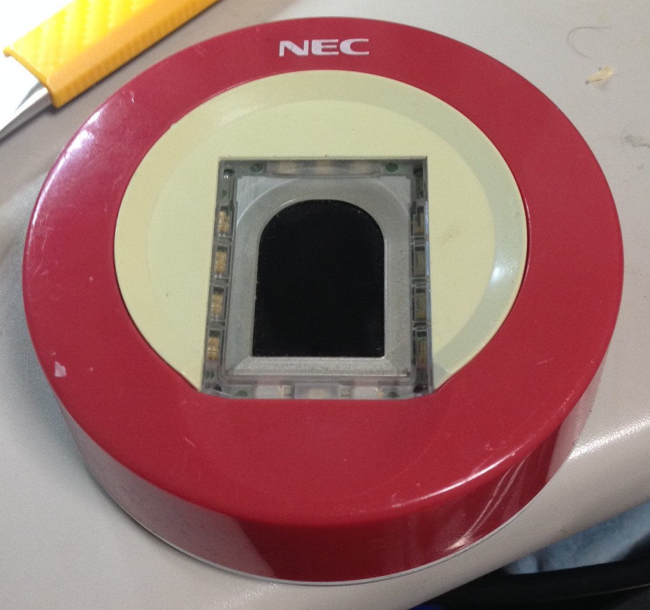
I picked up a finger print scanner on a whim in Akihabara the other day, it was only a dollar so I figured what the hell.

finger1

Looks pretty normal. I figured it would have a cheap USB controller inside.

finger2

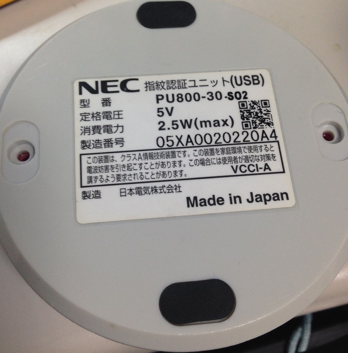
Model NEC PU800-30-S02. Hmm 2.5W… that seems kind of high…

finger3

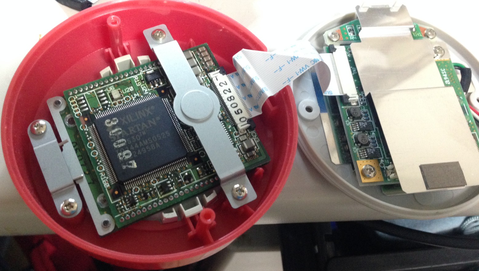
It’s got an FPGA in it!! Which explains the 2.5W I guess!

finger4

Not only that but a PXA255 too. Crazy powerful for what I assumed was a relatively dumb device.

MSP430 Development on Linux using the eZ430-F2013

msp430

Notes below are for debian wheezy:

apt-get install gcc-msp430 mspdebug
wget http://41j.com/blog/wp-content/uploads/2014/11/ti_3410.fw
sudo cp ti_3410.fw /lib/firmware/

#compile code and program device
wget http://41j.com/blog/wp-content/uploads/2014/11/myprog.c
msp430-gcc -Os -Wall -mmcu=msp430f2013 -std=gnu99 ./myprog.c -o myprog
sudo mspdebug uif -d /dev/ttyUSB0 'prog ./myprog'

notes

Useful information here on where to find firmware:
msp430 firmware

I’ve used the following makefile in the past with some success: download

This is the code I used for the test above:

#include <msp430x20x3.h>
int main (void) {
  WDTCTL = WDTPW | WDTHOLD;

  P1DIR = 0xFF;
  for(;;) {
    P1OUT=0;
    __delay_cycles(2500000);
    P1OUT=1;
    __delay_cycles(2500000);
  }
return 0;
}

CCD Notes

Some more random CCD notes, as I’ve been trying to figure out how the Ixy 60 CCd works..

The reference here which describes CCD interfacing in general has been very useful.

Typically a the CCD is interfaced using an AFE (analogue front end). Another camera I have uses this Casio part: AD9923, Datasheet.

This post has some notes in Russian on the Ixy 60. No idea what they’re doing but the drawings look awesome.

These youtube videos give a nice introduction to CCD.

Further random notes on the Ixy 60 CCD pinout

Pins 3 and 4 from bottom left appear to show differences with light when removed from circuit (pins 17 and 18 on my diagram). Analogue data.

CCD looks similar to MN39670 but I can’t find a datasheet for this anyway.

6,8,5,4 on flex PCB appear to be pixel clock?

On CCD
Possible pixel clocks
———————
pin 28: pixel clock? ~30ns period 33MHz? ~3v
pin 17: 30ns pulse ~4v
pin 18: 30ns sq. ~3 -> 4v
pin 19: as 18
pin 27: as 28

pin 1: 3us, 16v sq every 30ms. (inside 2 10us -8v sqs)
2.2us, 0-5.8us, 4.6us, -8v. every 124.8us
pin 3: as pin 1, but no +16v pulses.
pin 4: as pin 1, but 16v is in 2.4us sqs.
pin 5: as 4, but no pulse before 16v
pin 6: +10v, 20us, 0 5us, 16us
pin 7: -8, every 125us, + something…
pin 8: as 7
pin 9: as 7
pin 10: +8v, 20us, 0-4.4us, 14.4us. every ???
2.6us, 0-7.8us, 2.6us. every 125us
pin 11: as 7?
pin 12: as 10
pin 13: as 12
pin 14: as 12