Archive for the ‘Uncategorized’ Category.

Dual esp8266 board

espdual

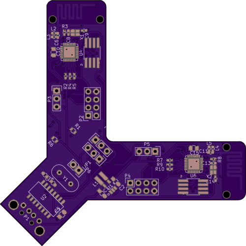
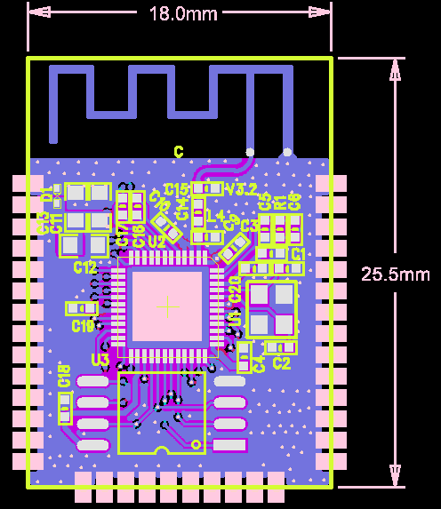
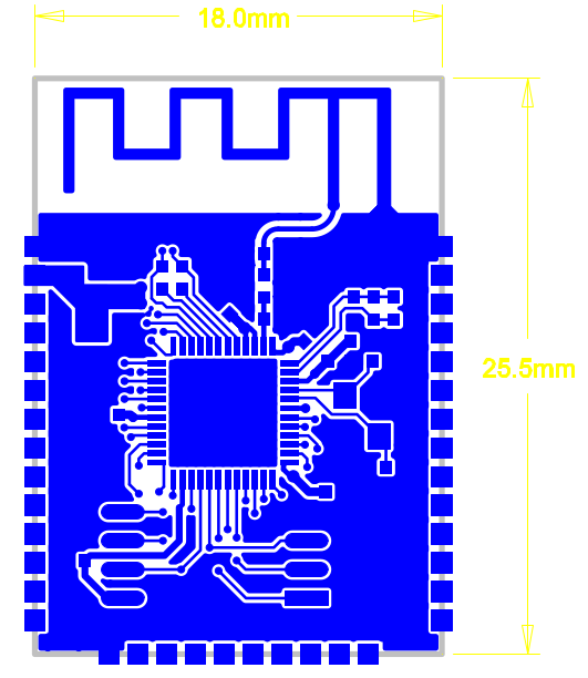
I’ve been playing with a new esp8266 design. The board has 2 esp8266s on one PCB. It’s based around my espusb design.

The board contains a ch340g usb interface, an MSP1603 buck converter to power the 2 esp8266s. The SPI buses of the esps are linked so that they can communicate. There are headers that allow the 2 esps to be programmed independently.

One idea of course is that I could uses these boards to build a basic mesh network. I think they’ll be fun to play around with in any case. Gerbers and Kicad files below. If boards work, and there’s any interest, I might stick them in my shop. If you think you’d like one email me ([email protected]).

Kicad design files and gerbers: espusb_dual

Weird PCB Layouts with Kicad

flowerpcb2

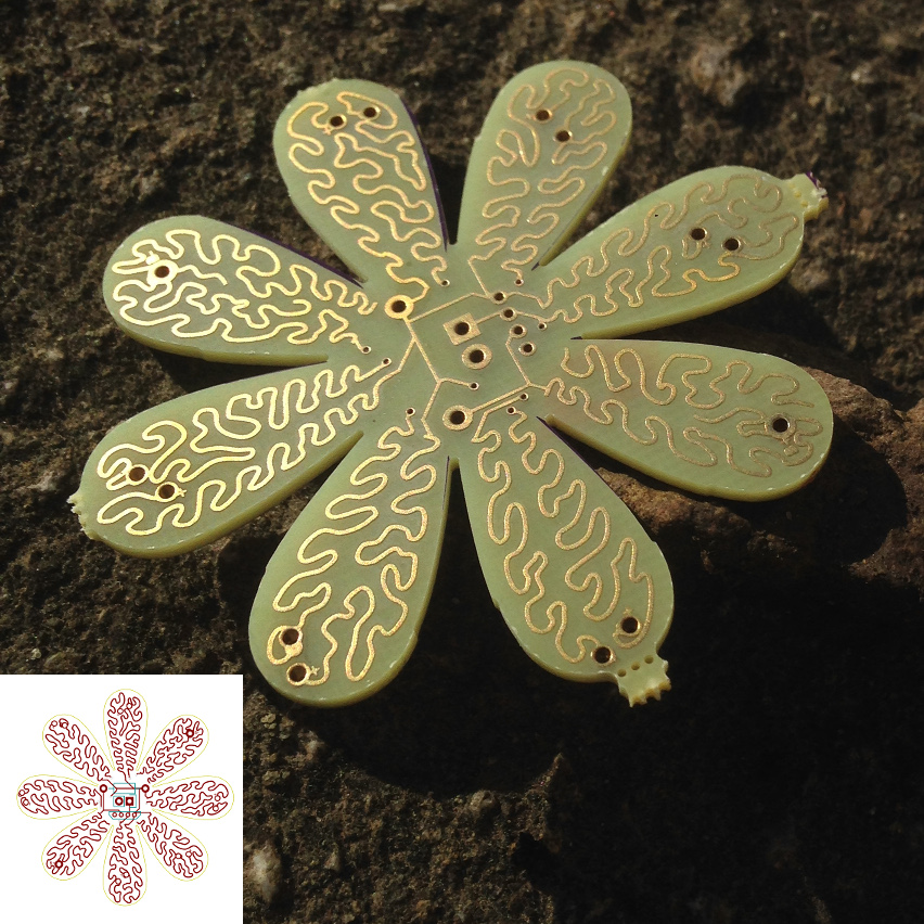
I designed the board above for my solar flower kit. It was partly an experiment is designing a weird shaped PCB, with funky traces and complex edges.

The process is kind of messy, and requires command line tools. If you’re a graphic designer and would like me to do this for you, click here. If you want to do this yourself, my notes are below.

The board edges have to be imported into Kicad separately from the graphics. You can only import DXF files. I use Inkscape to design the board edges and then export them as DXF. In Kicad in PCBnew select “File->Import->DXF” and import the DXF into the “Edges.cuts” layer.

First, I designed the flower shaped edge cut in Inkscape. In recent versions of KiCad it’s pretty easy to import the edgecuts. Firstly create your edges in Inkscape, ensure that the design is a simple line drawing and save it as a DXF file. Then just select “File->Import->DXF” in KiCad, and import the DXF into the Edge.cuts layer.

Creating interesting looking traces is more difficult. Kicad doesn’t really have a concept of non-straight line traces, and pads are similarly limited. There’s a tool in Kicad called “Bitmap2Component” which is ok for basic logos, but it doesn’t work that well with vector graphics.

For graphics I therefore use svg2mod. This is a neat little command line tool which takes a vector image into a Kicad component composed of a bunch of straight-line segments. After you’ve downloaded the tool you can run it as follows on an SVG:

./svg2mod.py -i ~/design.svg -o ~/design.mod -p 0.1

The “-p” parameter determines how many segments a curve is broken into, and may require some experimentation. svg2mod also works with multi-layer SVG files. You can create mask, copper, and silk layers and import them all into the Kicad component (the svg2mod readme specifies all the layer names you need to use).

You can them import the .mod component into Pcbnew and place it as you would any other part. In my case, I’d mark locations where LEDs should sit on the Inkscape design. I then placed LEDs over these in Pcbnew, this ensures that the drill holes get created correctly. I also had a small layout in the center of the board, the traces designed in Inkscape therefore needed to be manually aligned, and of course your DRC never passes.

That’s the basic process, and while it’s pretty messy but it works and you can create some entertainingly odd PCBs this way.

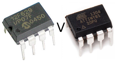
PIC Versus AVR

pic

As a general purpose microcontroller board I was always a bit disappointed with the Arduino. When in Arduino appeared in 2005 the 8bit AVRs were already pretty old school microcontrollers and cheap 32bit microcontrollers were already available. These days when you can pick up a cheap STM32 for under a dollar it seems kind fo crazy to use 8bit mid-90s technology…

The reason we do of course is because the Arduino has great support and a large active community.

For a recent project I wanted a small microcontroller. All it had to do was send a few very simple serial commands. For this, I really didn’t need anything more than an 8bit microcontroller, which for me comes down to PIC versus AVR.

I cut my teeth on PICs in the 90s using MPLAB under windows 3.11. PICs have a kind of nasty architecture. They’re Harvard architecture. Which means code and data sit in separate memory spaces, and that takes a little getting used to.

One of the nice things about PICs is that very have very very low power, cheap versions. The PIC12F629 has ~2KB of flash and 64 bytes of RAM. It’s about 1USD on digikey and about 10 cents on taobao. It also looks like there might be cheaper clones down to about 1 cent.

So I went with the PIC12F629 and it was a nightmare. Firstly, I thought I’d try using a C compiler, inefficient for sure but hopefully quicker than writing assembler. So I installed the debian package sdcc, which is the only compiler I know that supports PICs on Linux.

Debian sdcc doesn’t have PIC support.

sdcc uses the microchip header files which have a non-free license. It look me a while to figure this out but I then downloaded sdcc for their sourceforge site.

It’s a sourceforge site. I should probably have stopped right there. Binaries are available, but they are 32bit only. I checked out the source from their svn.

./configure;make;make install

Looks good. Could at least start to compile code, lots of issues. Size issues due to 32bit in library requirements (removed 32bit ints) etc. etc. Finally code looks like it should fit in the flash, but it’s failing to link with libsdcc.

Building sdcc doesn’t build libsdcc. Googling… digging around in random directories, and try and configure;make it. Fails. Missing instructions in the floating point library. Hack the floating point library until it builds…

Finally get a binary from sdcc.

I’m using a minipro to flash the controller. Fails.. the hex file is the wrong size.

The hex file contains a single word way off the end of the flash memory. This was actually the configuration bit, but the Linux minipro software doesn’t know how to flash this correctly. However with this removed the devices would flash and verify.

PIC does nothing when powered. Can’t even get an LED to blink.

I try reference hex files which should just blink LEDs… they don’t work.

I figure maybe the Linux minipro client doesn’t work well. So I try the Windows client. Many people have reported successes with minipro and the PIC (including the PIC12F629) so it should be an issue.

Fails.

Spend hours fiddling with config bits. Decoupling.. Power supplies..

Fails.

Give up, and buy a Digispark with a ATTINY85. Works within 5 minutes.

I’d literally spent hours with the PIC. I’m guess one possibility is that I’d overwritten the OSCVAL config in the PICs (which stores internal oscillator calibration) and the PIC was hosed because of this. But the conclusion is basically the same.

The AVR has a clean, open toolchain and a larger community, it’s just easier to get things done. At some point I’ll likely migrate my code to the ATTINY10 which are about the same price as the cheapest PICs (
Creating the miror swtich

FullSizeRender(8)

Since I last wrote about adding management features to a cheap 5 port switch I’ve been trying to productionize that work.

I wanted to load the switch with a static config, enabling port mirroring from ports 0 to 1 as a network diagnostics tool (plug: you can now buy this on my shop).

The ip178g can load its config from flash at boot, and the flash IC footprint is on the board. Great! Should be easily… well turns out not so much. The flash used is an AT24C01, this was superseded by the AT24C01A and is no longer available from the normal suppliers. I had a lot of fun figuring this out (and no they’re not compatible).

Ordering the part from Shenzhen would take a month, and because the AT24C01A is also thrown around prety freely I’m not confident that I’d get the right part anyway.

So, I decided to use an ATTINY85. Actually at first I decided to use a PIC12F629 (this was a horror story in itself). I purchased some digisparks and used code adapted from my previous post to send config messages to the IP178G. It would also be possible to simulate the the AT24C01, which might be an interesting project.

Before I gave up on the AT24C01 route I wrote a flash image builder. You can find this can the digispark code on github.

To mount the ATTINY85 in the switch I pulled it off the digispark and placed it on the AT24C01 footprint. For the most part the pins line up acceptably well. The ATTINY85 is a wider part, and a pullup resistor needs to be added to the reset pin, but this is an acceptable solution for now (the rework is shown above).

Digispark code is below for reference:

int clock_pin = 1;
int data_pin  = 0;
 
int width=100;
 
void setup() {
  pinMode(clock_pin, OUTPUT); // CLOCK
  pinMode( data_pin, OUTPUT); // DATA
}
 
int recv_one_bit() {
  int data=0;
  digitalWrite(clock_pin,0);
  delayMicroseconds(width);
  digitalWrite(clock_pin,1);
  delayMicroseconds(width/2);
  data = digitalRead(data_pin);
  delayMicroseconds(width/2);
  digitalWrite(clock_pin,0);
  return data;
}
 
void send_data_bit(int data) {
  digitalWrite(clock_pin,0);
  delayMicroseconds(width/2);
  digitalWrite(data_pin,data);
  delayMicroseconds(width/2);
  digitalWrite(clock_pin,1);
  delayMicroseconds(width);
  digitalWrite(clock_pin,0);
}
 
void outhigh() {
  pinMode(data_pin,OUTPUT);
  digitalWrite(data_pin,1);
  digitalWrite(clock_pin,0);
}
 
void send_data(uint32_t data,int len) {
 
  for(int32_t n=len-1;n>=0;n--) {
    if(data & ((uint32_t)1 << n)) { send_data_bit(1); } else { send_data_bit(0); }
  }
} 


uint32_t recv_data(int len) { uint32_t datain = 0; for(int32_t n=(len-1);n>=0;n--) {
    int d = recv_one_bit();
    if(d != 0) {
      datain = datain | (uint32_t)((uint32_t)1 << n);
    }
  }
  return datain;
}
 
uint32_t read_op(int phy,int reg) {
   
  pinMode(data_pin,OUTPUT);
  send_data_bit(1);
   
  send_data_bit(0); // start bits
  send_data_bit(1);
  send_data_bit(1); // read operation
  send_data_bit(0);

  send_data(phy,5);
  send_data(reg,5);
 
  pinMode(data_pin,INPUT);
   
  uint32_t in;
  int inA = recv_one_bit(); // turn around
  //int inB = recv_one_bit(); // this should be required as per spec, but a bit gets missed if I use it.
   
  in = recv_data(16);
 
  outhigh();
   
  return in;
}
 
 
void write_op(int phy,int reg,uint32_t data) {
   
  pinMode(data_pin,OUTPUT);
  send_data_bit(1);
 
  send_data_bit(0);
  send_data_bit(1);
  send_data_bit(0);
  send_data_bit(1);
         
  send_data(phy,5);
  send_data(reg,5);
   
  send_data_bit(1);
  send_data_bit(0);
//  send_data(2,2); // Turnaround - required by spec, but causes issues.
   
  send_data(data,16);
}
 
void loop() {

  outhigh();
  delay(5000); // one second
   
  //Port mirroring config sits in phy 20, regs 3 and 4.
  //The bit pattern is shown below. See the datasheet for further details.
  //15.......................0  
  //   enable, mode, res, mirrored port rx
  //3: 1,   11,00000,00000001
  //
  //   monitoring port, res, mirrored port tx
  //4: 001 ,00000,00000001  
   
  uint32_t reg3 = 0xE001;
  uint32_t reg4 = 0x2001;
   
  write_op(20,3,reg3);
  write_op(20,4,reg4);
  delay(1000*30); // 30s
}