Archive for the ‘Uncategorized’ Category.

Notes on using a ILX511 Linear CCD, AD9225 ADC, ICE40HX8K and Nmigen

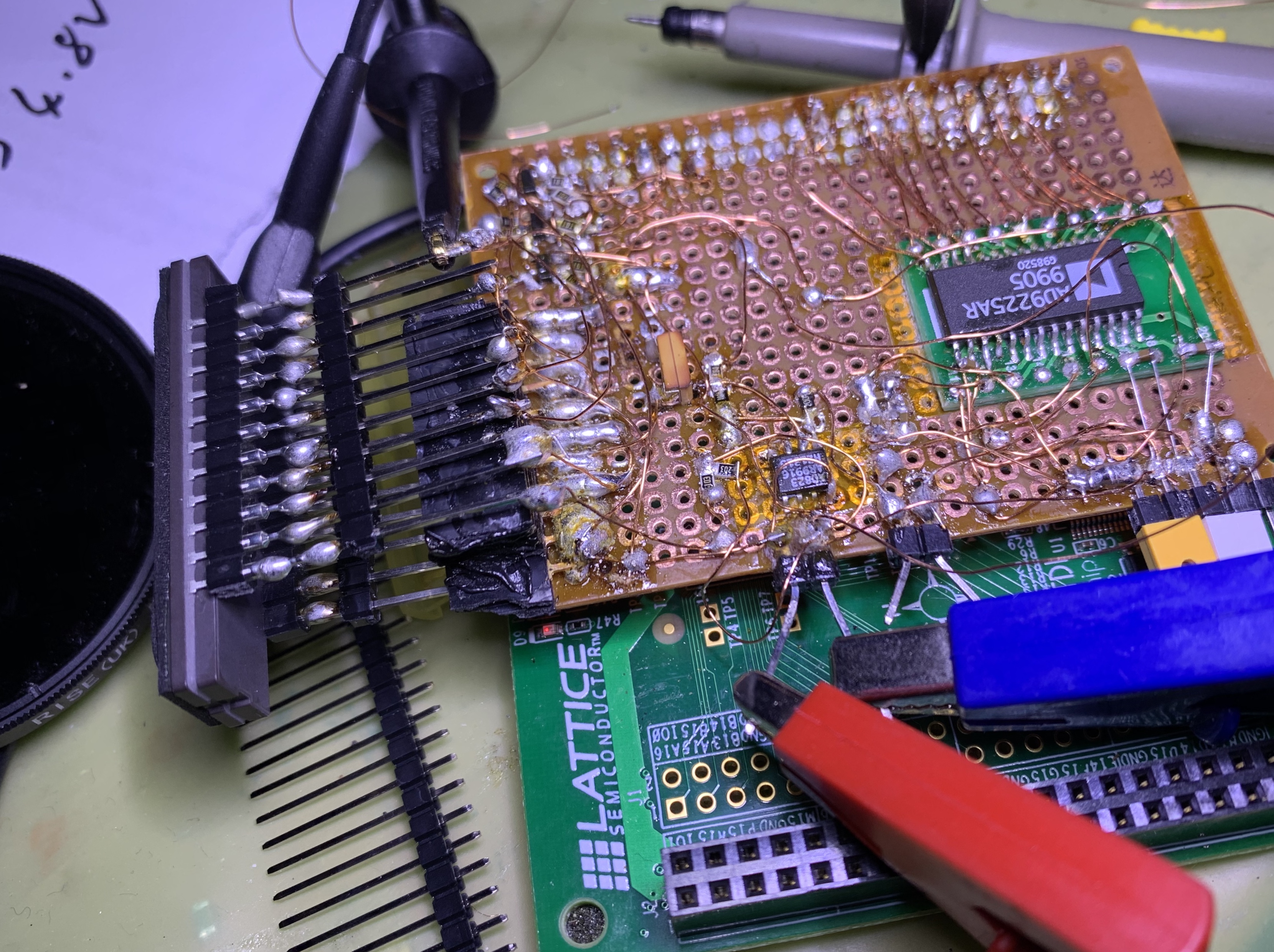
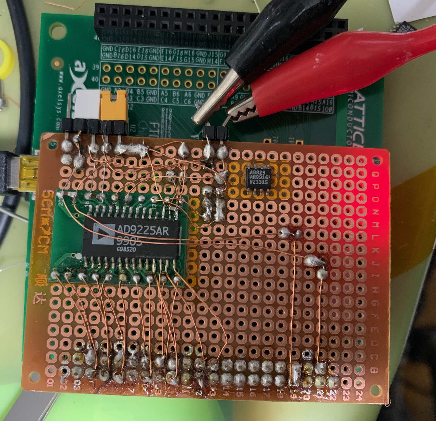
The messy pile of hacks above is my first attempt at getting an ILX511 Linear CCD working. I’m using a ICE40HX8K FPGA (Lattice evaluation board). An AD9225 ADC is used to acquire data. An AD823 is used to amplify the signal from the CCD. 2N7002s are used to convert the 3.3v signals to 5v for the CCD. I needed to use 1K pullups to get the required 100ns rise time required…

The horribly filmed scope trace below shows the ROG signal (resets to start of frame) and amplified Vout.

The setup is quite sensitive. I had to use a ND1000 (ND 3.0) in front of the filter. In the video above I’m running a laser pointer back an forth across the CCD, and you can see the peak move relative to the ROG impulse.

The code below is used to drive the CCD. Both the code below and the board are horrible messes. There seem to be a few issues with the code and the output is not as clear as shown in the scope trace. Part of the issue is likely that I’m trying to write data out to the UART as I’m acquiring it. I need to buffer one line (or pixels) and then dump it out to the UART…

But everything more or less works, and it’s probably time to design a PCB if I want to move forward. I’ll then have something stable to work with when rewriting the code. A tarball of the code is here. A listing is also below, it uses the pll code from kbob (modified for the HX8K on the evaluation board) and uart.py from the nmigen repository.

#!/usr/bin/python3

from nmigen import *
from uart import *
from nmigen_boards.ice40_hx8k_b_evn import *
from nmigen.build import *

from pll import PLL


class Top(Elaboratable):

    def elaborate(self, platform):
        # B1 is clock
        adcclk = [ Resource("ad9225clk", 0, Pins("B1", dir="o"), Attrs(IO_STANDARD="SB_LVCMOS")) ]

        adc = [ Resource("ad9225", 0, Pins("B2 C1 C2 D1 D2 E2 F1 F2 G2 H1 H2 J2", dir="i"),  Attrs(IO_STAN
DARD="SB_LVCMOS")) ]

        # pins 3 4 11
        ilx511shsw = [ Resource("ilx511shsw", 0, Pins("N3", dir="o"), Attrs(IO_STANDARD="SB_LVCMOS")) ]
        ilx511clk  = [ Resource("ilx511clk" , 0, Pins("N2", dir="o"), Attrs(IO_STANDARD="SB_LVCMOS")) ]
        ilx511rog  = [ Resource("ilx511rog" , 0, Pins("M2", dir="o"), Attrs(IO_STANDARD="SB_LVCMOS")) ]

        platform.add_resources(adc)
        platform.add_resources(adcclk)
        platform.add_resources(ilx511shsw)
        platform.add_resources(ilx511clk)
        platform.add_resources(ilx511rog)


        # PLL Stuff

        # If you don't specify dir='-', you will experience a world
        # of debugging pain.
        clk_pin = platform.request(platform.default_clk, dir='-')

        m = Module()
        pll = PLL(freq_in_mhz=12, freq_out_mhz=24)

        m.domains += pll.domain     # override the default 'sync' domain

        timer = Signal(28)
        timerRog = Signal(28)

        #Connect TX to B12
        led0     = platform.request('led', 0)
        muart    = platform.request('uart')
        data     = platform.request('ad9225',0)
        dataclk  = platform.request('ad9225clk',0)
        ccd_shsw = platform.request('ilx511shsw',0)
        ccd_clk  = platform.request('ilx511clk',0)
        ccd_rog  = platform.request('ilx511rog',0)
        dataA = Signal(8)
        rdy   = Signal(1)

        with m.If(timer[8]): #9
            m.d.sync += [
              rdy.eq(1),
              timer.eq(0)
            ]
        with m.Else():
            m.d.sync += [
                timer.eq(timer + 1)
            ]


        timerD = Signal(4)
        m.d.sync += [
            timerD.eq(timerD+1)
        ]
        with m.If(rdy == 1):
            m.d.sync += [
                rdy.eq(0)
            ]

        with m.If(timerRog[15]): #16
            m.d.sync += [
              ccd_rog.eq(1),
              timerRog.eq(0),
              timerD.eq(0),
              timer.eq(0),
              dataA.eq(0x0A),
              rdy.eq(1)
            ]
        with m.Else():
            m.d.sync += [
                timerRog.eq(timerRog + 1),
                dataA.eq(data.i[8:11] + 0x2E),
            ]

        with m.If(timerRog[11]):
            m.d.sync += [
                ccd_rog.eq(0),
            ]


        with m.If(ccd_rog == 0):
            m.d.sync += [
                ccd_clk.eq(timerD[-1])
            ]
        with m.Else():
            m.d.sync += [
                ccd_clk.eq(0)
            ]

        m.d.comb += [
            pll.clk_pin.eq(clk_pin),
            dataclk.eq(timer[5])
        ]

        m.d.comb += [
            ccd_shsw.eq(1) # use Sample and Hold.
        ]

        # UART

        uart = UART(divisor=208)
        uart.tx_o = muart.tx


        m.d.comb += [
            uart.tx_data.eq(dataA),
            uart.tx_rdy.eq(rdy)
        ]

        m.submodules += [pll, uart]

        return m


if __name__ == '__main__':
    platform = ICE40HX8KBEVNPlatform()

    platform.build(Top(), do_program=True)

Logomaker quick example

I wanted to use Logomaker to make a sequence logo. While the documentation is pretty good there wasn’t an example that showed exactly what I wanted. Most likely this is obvious if you’re familiar with Pandas.

The code below will load sequence probabilities from a tsv file, create a sequence logo and save it to logo.png

import numpy as np
import pandas as pd
import matplotlib.pyplot as plt

import logomaker

ss_df = pd.read_csv('all.tsv', sep="\t", index_col=0)

# create Logo object
ss_logo = logomaker.Logo(ss_df,
                         width=.8,
                         color_scheme='NajafabadiEtAl2017',
                         vpad=.05)

ss_logo.ax.set_ylabel('probability')

plt.savefig('logo.png')

all.tsv contains the following:

pos     A       T       G       C
0       0.1     0.2     0.3     0.4
1       0.1     0.2     0.3     0.4
2       0.1     0.2     0.3     0.4
3       0.1     0.2     0.3     0.4
4       0.1     0.2     0.3     0.4
5       0.1     0.2     0.3     0.4
6       0.1     0.2     0.3     0.4
7       0.1     0.2     0.3     0.4
8       0.1     0.2     0.3     0.4
9       0.1     0.2     0.3     0.4

ICE40HX8K AD9225 ADC with Nmigen

This is a first stab at getting the AD9225 ADC working with the ICE48HX8K. I don’t really know my way around python or Nmigen, so these notes most likely do not represent the right way of doing things. But it somewhat works…

The AD9225 is a part pulled from an old CCD camera. It’s a 25MSPS 12bit ADC. I’m not driving it this fast in this test, nor is the UART currently dumping all 12bits. Most likely the Resource can be better refactored so that the clock and data pins are part of the same Resource… Anyway, here’s the code:

#!/usr/bin/python3

from nmigen import *
from uart import *
from nmigen_boards.ice40_hx8k_b_evn import *
from nmigen.build import *

from pll import PLL


class Top(Elaboratable):

    def elaborate(self, platform):
        # B1 is clock
        adcclk = [ Resource("ad9225clk", 0, Pins("B1", dir="o"), Attrs(IO_STANDARD="SB_LVCMOS")) ]

        adc = [ Resource("ad9225", 0, Pins("B2 C1 C2 D1 D2 E2 F1 F2 G1 G2 H1", dir="i"),  Attrs(IO_STANDARD="SB_LVCMOS")) ]
        platform.add_resources(adc)
        platform.add_resources(adcclk)

        # PLL Stuff

        # If you don't specify dir='-', you will experience a world
        # of debugging pain.
        clk_pin = platform.request(platform.default_clk, dir='-')

        m = Module()
        pll = PLL(freq_in_mhz=12, freq_out_mhz=96)

        m.domains += pll.domain     # override the default 'sync' domain

        timer = Signal(28)

        #Connect TX to B12
        led0 = platform.request('led', 0)
        muart = platform.request('uart')
        data  = platform.request('ad9225',0)
        dataclk  = platform.request('ad9225clk',0)
        dataA = Signal(8)
        rdy   = Signal(1)

        with m.If(timer[25]):
            m.d.sync += [
              rdy.eq(1),
              timer.eq(0)
            ]
        with m.Else():
            m.d.sync += [
                timer.eq(timer + 1)
            ]

        with m.If(rdy == 1):
            m.d.sync += [
                rdy.eq(0)
            ]


        m.d.sync += [
            dataA.eq(data.i[0:8] + 0x60),
        ]

        m.d.comb += [
            pll.clk_pin.eq(clk_pin),
            dataclk.eq(timer[20])
        ]

        # UART

        uart = UART(divisor=10000)
        uart.tx_o = muart.tx


        m.d.comb += [
            uart.tx_data.eq(dataA),
            uart.tx_rdy.eq(rdy)
        ]

        m.submodules += [pll, uart]

        return m


if __name__ == '__main__':
    platform = ICE40HX8KBEVNPlatform()
    platform.build(Top(), do_program=True)

The above code should output ADC values via the FT2232. This is what I get when driving the ADC with a 0.1Hz 3v square wave. The AD9225 is running at 3.3v (analog and digital):

jbnb_______________bmjalaocbkbka______________ckklbmbmamoc_______________clakbobnbmldh______________nbmblajboblald______________akbkmobmn_ka_______________cncmal]h_lelk______________kbm_

Nmigen UART Notes

I’ve been stumbling my way through nmigen. As I slowly figure things out, I’m dumping my notes here in case they prove useful…

The following is for the ICE40 HX8K evaluation board. It uses the uart.py example from the nmigen repository. The code will write bursts of a’s at 9600bps.

#!/usr/bin/python3

from nmigen import *
from uart import *
from nmigen_boards.ice40_hx8k_b_evn import *

class Top(Elaboratable):

    def elaborate(self, platform):

        m = Module()
        timer = Signal(26)

        #Connect TX to B12
        muart = platform.request('uart')

        m.d.sync += [
            timer.eq(timer + 1)
        ]

        uart = UART(divisor=1250)
        uart.tx_o = muart.tx

        m.d.comb += [
            uart.tx_data.eq(0x61),
            uart.tx_rdy.eq(timer[-1])
        ]

        m.submodules += [uart]

        return m

if __name__ == '__main__':
    platform = ICE40HX8KBEVNPlatform()

    platform.build(Top(), do_program=True)

This code sets tx_rdy high based on a counter. This means that tx_rdy stays high for multiple clock cycles. And as I understand it, the uart will continue to output for this period. The code above is available in this tarball.

The following code uses the uart to write data from some pins on the header of the ICE40 HX8K evaluation board. It adds 0x60 to the value from these pins so low values are in a readable range. A counter is used to set the UART ready signal high once every ~0.7s. There’s probably a better way of doing this… the code is also available in the tarball here.

#!/usr/bin/python3

from nmigen import *
from uart import *
from nmigen_boards.ice40_hx8k_b_evn import *
from nmigen.build import *

class Top(Elaboratable):

    def elaborate(self, platform):
        inpins = [ Resource("inpins", 0, Pins("B1 B2 C1 C2 D1 D2 E2 F1"), Attrs(IO_STANDARD="SB_LVCMOS")) ]
        platform.add_resources(inpins)

        m = Module()

        timer = Signal(24)

        #Connect TX to B12
        led0 = platform.request('led', 0)
        muart = platform.request('uart')
        data  = platform.request('inpins',0)
        dataA = Signal(8)
        rdy   = Signal(1)

        with m.If(timer[-1]):
            m.d.sync += [
              rdy.eq(1),
              timer.eq(0)
            ]
        with m.Else():
            m.d.sync += [
                timer.eq(timer + 1)
            ]

        with m.If(rdy == 1):
            m.d.sync += [
                rdy.eq(0)
            ]

        m.d.sync += [
            dataA.eq(data.i[0:8] + 0x60)
        ]

        m.d.comb += [
            led0.eq(timer[-1])
        ]

        # UART
        uart = UART(divisor=1250)
        uart.tx_o = muart.tx


        m.d.comb += [
            uart.tx_data.eq(dataA),
            uart.tx_rdy.eq(rdy)
        ]

        m.submodules += [uart]

        return m

if __name__ == '__main__':
    platform = ICE40HX8KBEVNPlatform()
    platform.build(Top(), do_program=True)