Archive for the ‘Uncategorized’ Category.

Tektronix TDS7054 Repair

I picked up a TDS7054 as junk for 200USD the other day. This was a pretty good deal considering the original list price was >20000USD, and they still go for 5000USD on ebay regularly. This post documents the fault and repair. When powered on the instrument wouldn’t display anything on either the scope VGA or the PC VGA interfaces. The TDS7000 and TDS5000 series scopes have kind of a weird architecture. They are effectively standard x86 PCs coupled with a PowerPC system running VXWorks which interfaces with the acquisition hardware and I guess does most of the signal analysis work.

The PowerPC system is attached to the x86 system via a PCI bus, from is connected to the acquisition and powersupply via a backplane. The following block diagram describes the setup:

TDS5000_2

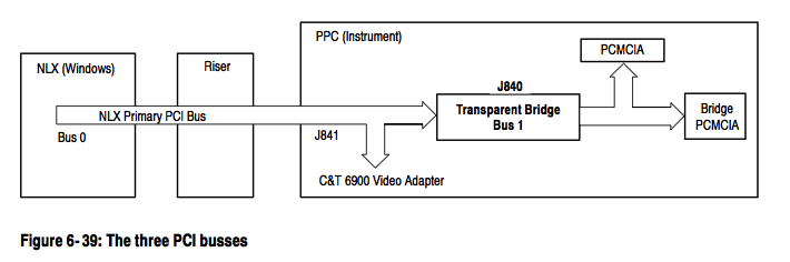
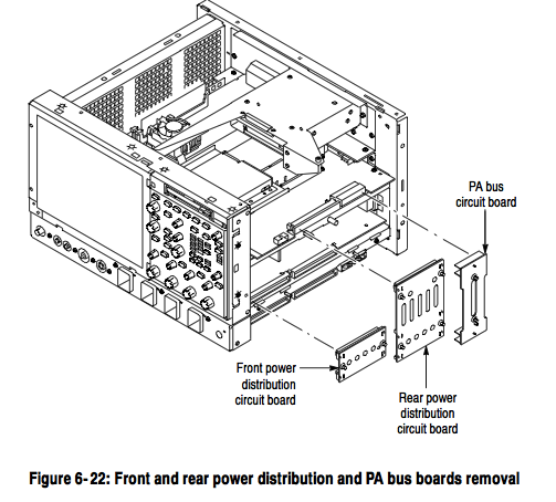
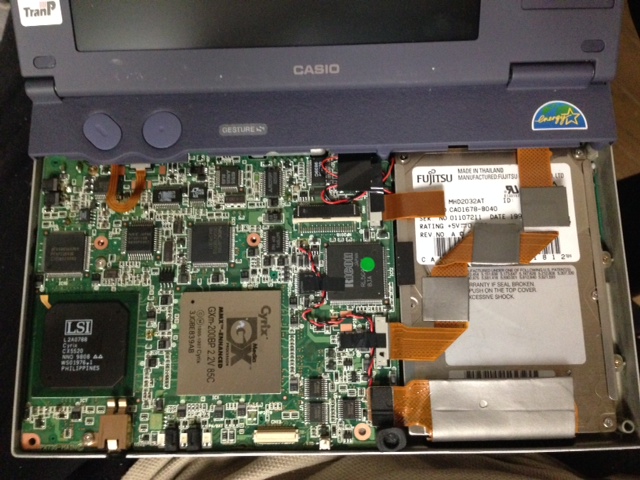
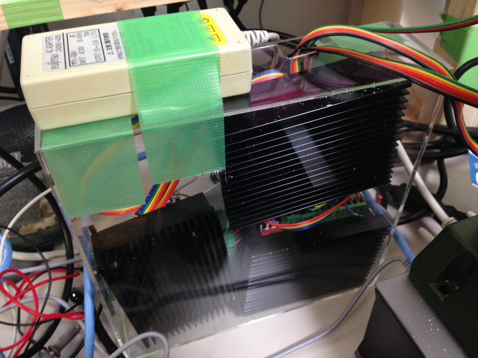
Physically the boards are sit on top of each other, the x86 host on the top, the PowerPC board directly under that connected via the PCI bus and the acquisition and power supply under this. This makes debugging pretty difficult, as the PowerPC hardware wont power up without the x86 board in place. Luckily the fault I had was pretty straightforward. The diagram below shows the physical layout:

TDS7000_1

Debugging is further complicated by the fact that the PC has 2 video adapters, one that is directly on the x86 motherboard, and another which sits on the PCI bus and is attached to the scope hardware. The PowerPC and x86 hardware share the PCI graphics card (as far as I can tell) and the PowerPC is able to write data directly to the framebuffer there (and this is how it plots scope traces, at least this appears to be the case of the TDS5000). The PowerPC also somehow shares access to the HDD, and loads Vxworks from this, the HDD being connected to the PCI (and other signals) connector that sits between the 2 boards.

Debugging

As mentioned the device showed nothing on either VGA port at first. In order to get any output I needed to do a CMOS RAM reset on the PC hardware (there’s a CMOS RAM reset jumper next to the battery, or you can just remove the battery). After this is started outputting to it’s VGA port. However it wouldn’t see the HDD and just reported “A: Drive Error”. It would not enter the setup screen of the bios, even though the system said “Entering BIOS”. The motherboard has a modified BIOS to work with these scopes, and it seems like this is the cause of the weird behaviour.

My guess is that it couldn’t see the HDD because the PowerPC board wasn’t coming up correctly, after VXWorks boots, I believe it hands control of the HDD over to the x86 system.

The diagnostic 7-segment display showed “.A”. The “.” means that the diagnostic stopped at this point. The “A” is documented in the service manual as being an NVRAM check.

Next I attached a console to the serial port on the PowerPC board. It’s conveniently labeled “console” and the second and third pins from the top right provide a serial console ( 9600 8N1 ). This is a real (not TTL level) RS232 serial port, and most USB serial port adapters wont work (they run slightly out of spec and don’t provide a full 12 volt swing). I had to dig out an old PC with a real serial port for this.

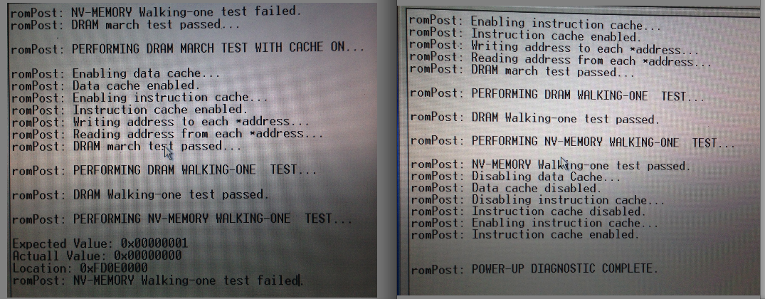
The console showed the error below on the left. You can see the error where diagnostics failed “NV-MEMORY Walking-one test failed”. The screenshot on the right is what you should see (taken after the system was repaired).

scopefail

This indicated a fault accessing the NVRAM module. There’s a picture of this module here and this is my module with the “powercap” removed:

powercap

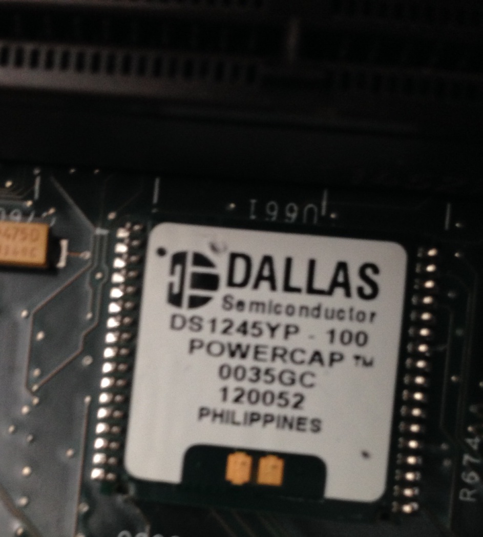
I checked it was receiving power, which is was and ordered a replacement module. Luckily after replacing the module, the diagnostic passed and the console output on the right of the picture above was shown. I also replaced the battery on the NVRAM module, which was low.

However the scope didn’t boot. Next the CMOS settings need resetting, and you still can’t enter the BIOS config on boot. For this you need a DOS boot floppy! You’ll also need some files from the system from the system HDD. The CMOS programming tool you need is in the following location: C:\Tektronix\CMOS (from memory). I attached the PATA drive via a USB converter to a PC and copied the files. However seeing as it’s been about 10 years since I had a DOS boot disc that was more challenging, I managed to find a USB floppy drive and some discs and somehow put a working bootdisc together and copied over the CMOS programming utility. I then booted from this and used CMOS.EXE -r NONET (again from memory) to restore the CMOS setting.

After this the system booted successfully:

scopefix

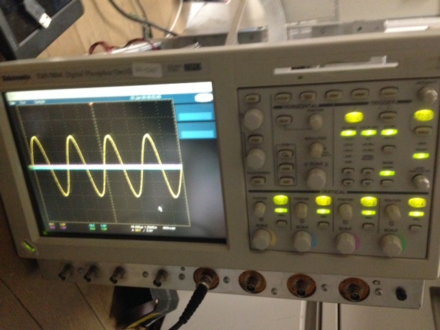
The reassembled scope is awesome, but pretty huge. It now lives out on Tokyo Hacker Farm, where I hope it will get some good use!

This EEVBlog forum entry was also very helpful and has a bunch of useful information, he also wrote up his notes here.

Siglent SDG1020 Arb data format

The Siglent SDG1020 comes with a wave form generating package for Windows XP and Vista. It’s called EasyWave. In order to install this you’ll need the NI VISA runtime (otherwise you’ll get a rather un-descriptive error saying “VISA32.DLL could not be found”. Once installed you can draw waveforms and either save them to a USB stick or program them to the device over USB (though I’ve never tried this).

However the file format appears to just be a modified CSV of the following format (and yes, the typo is written by the supplied software tool). It appears to be a DOS formatted file. A full example file is here

data lenth,16384
frequency,0.100000000
amp,20.000000000
offset,0.000000000
phase,0.000000000

xpos,value
0.000000e+000.6f,-0.974930362
6.103516e-004.6f,-0.972382425
1.220703e-003.6f,-0.969834487
1.831055e-003.6f,-0.967286550
2.441406e-003.6f,-0.964738613
3.051758e-003.6f,-0.962190675
3.662109e-003.6f,-0.959642738

9.996338e+000.6f,-0.974930362
9.996948e+000.6f,-0.974930362
9.997559e+000.6f,-0.974930362
9.998169e+000.6f,-0.974930362
9.998779e+000.6f,-0.974930362
9.999390e+000.6f,0.000000000

Casio Cassiopeia MPC-101M32 disassembly

Here are some pics of the Casio Cassiopeia MPC-101M32. It appears to be a pentium era laptop. I pulled it apart to switch out the PSU connector. It’s a nice laptop to hacker around with (for 10USD).

photo 4

photo 3

photo 2

photo 1

Proxxon MF70 CNC Kit

full

I’ve been playing with a Proxxon MF70 CNC conversion, these are my notes in case I ever need to revisit the project, or if they’re useful for anyone else. I purchased the stepper fittings on ebay from seller mbbilici. He has two versions, and I used the NEMA17 kit. Here’s the kit as it arrived:

kit

There are a couple of problems with it, the first is that the instructions are awful, and this kit seems different (actually nicer in a lot of ways) than many others on the Internet. This means that if you google for instructions you get confused. I ended up pulling apart half the XY stage before realizing that the kit only requires you to remove the handles and screw into the hole where the handle sits. This is actually really nice, because you can make a non-permanent modification to the Proxxon and return the mill to it’s stock configuration quite easily. This second issue is that the Z-axis stepper mount doesn’t fit on my Proxxon. The kit comes with Torx screws which simply don’t fit the holes in the plastic at the top of the mill, they’re too small and fall though.

I therefore needed to buy new screws (the ones that come with the Proxxon are too short) and drill out the mounting plate as the hole in the plate wasn’t big enough for the screws. These are the screws I bought:

screws

The Z-axis also seemed slightly too short. I had to add a couple of washers so that the Stepper spindle wasn’t push in:

zaxis

Those were the only serious modifications, everything else was pretty easy to install. I used the steppers mentioned in a dip

In addition to this, I also purchase the chuck attachment for the mill, and the steal vise. These are not strictly required. The motors were wired up to the driver controller and drivers. I did not connect the enable lines, they are active low, and when connected should you wire them to a physical estop switch. I may do that at some point. I’m using a 12V 3A switching powersupply from my junk pile as the power source for the stepper drivers. The controller board can be powered over USB (though this is not used for control signals).

The driverboard comes with instructions for MACH3 so that’s the software I’ve been using so far. I’d like to try EMC2. The driverboard talks to the PC via an old style parallel port. Almost all CNC controller boards seem to use parallel ports, what’s more USB parallel port adapters wont work. For this reason I picked up an old 30USD PC to use as a mill workstation. The trial version of MACH3 and Lazycam only supports 50 GCode instructions. So you wont get far without the getting the full version. This is annoying, because the demo doesn’t tell you it has this limitation, it just stops. So you I spent a bunch of time debugging this before I realized it was a demo limit.

You need to configure the parallel port pins in MACH3, here are my settings:

mach3a

And you also need to configure the motor parameters. There is likely some tweaking to do, but I used the following values which seem to work at the moment:

mach3b

Be careful to click “Save Axis Settings” here. Once everything is configured you can test it out. Power up the steppers (obviously don’t turn on the mill yet). You can now press tab and and bring up the jog whell. This lets you manually control the mill, you should test the motion of the X/Y/Z axis. I’d also recommend trying some manual milling via the steppers.

After all this you should be ready to go. MACH3 comes with LazyCam, you can export dxf’s from something like Solidworks and important them into LazyCam, this will prepare GCode for MACH3 Mill to use.

I’ve only just completed the first test cut, here it is:

crop2

That’s it so far! Here are some additional pictures of the driver board and completed rig:

drivers

drivers2

full2

xaxis

yaxis