Archive for the ‘Uncategorized’ Category.

Canon Ixy 60 (Powershot SD450)

ixy60_frontpcb

I’ve been playing with some Canon Ixy 60s which I picked up for 5USD in the junk bins of Akihabara. The camera uses a 5MP CCD sensor. I’m interested in understanding the protocol used to communicate with this sensor better. This post documents my notes so far.

I could just about get the thing to power up while disassembled by jaming the battery door sensor closed and pressing the power button:

ixy_jam

I then taped everything down, so I could probe around. It’s still annoying that it powers off every 30s or so:

ixy_60_tape1

I assigned pin numbers to the CCD pins as follows:
ixy_60_ccd

I then removed the CCD from the FPCB, hopefully I didn’t damage the FPCB in the process. Interestingly the camera still powers up. If you short the pins in the bottom left corner you even get something on the screen.

ixy_ccd_fpcb

Notes

I saved scope traces for all the pins below (clearly a bunch are ground, but hey).

Pin1: 1
Pin2: 1
Pin3: 1
Pin4: 1
Pin5: 1
Pin6: 1
Pin7: 1
Pin8: 1
Pin9: 1
Pin10: 1
Pin11: 1
Pin12: 1
Pin13: 1
Pin14: 1
Pin15: 1
Pin16: 1
Pin17: 1
Pin18: 1
Pin19: 1
Pin20: 1
Pin21: 1
Pin22: 1
Pin23: 1
Pin24: 1
Pin25: 1
Pin26: 1
Pin27: 1
Pin28: 1

DPReview

BGA Reballing experiments

bga_final

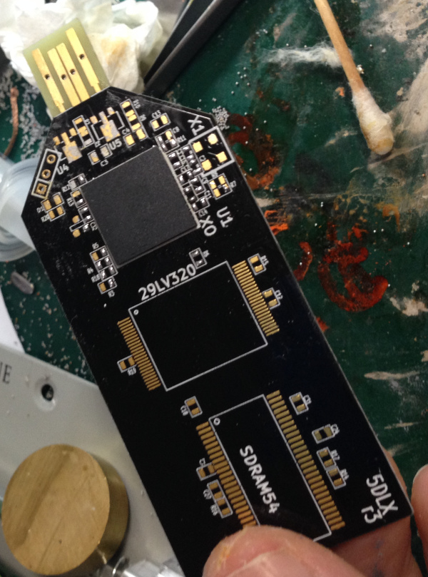
I removed the BGA part for the board, using a WEP 858D hot air rework station (flow rate 8, 350degrees). I let the part heat up for some time before applying pressure, to try and avoid pulling any pads off the chip.

I then cleaned up the part, apply a bunch of flux (any flux I had lying around, I think at this point I used goot BS-75B). Dragged a soldering iron (FX888, 350degrees) across the chip to pick up big blobs of solder.

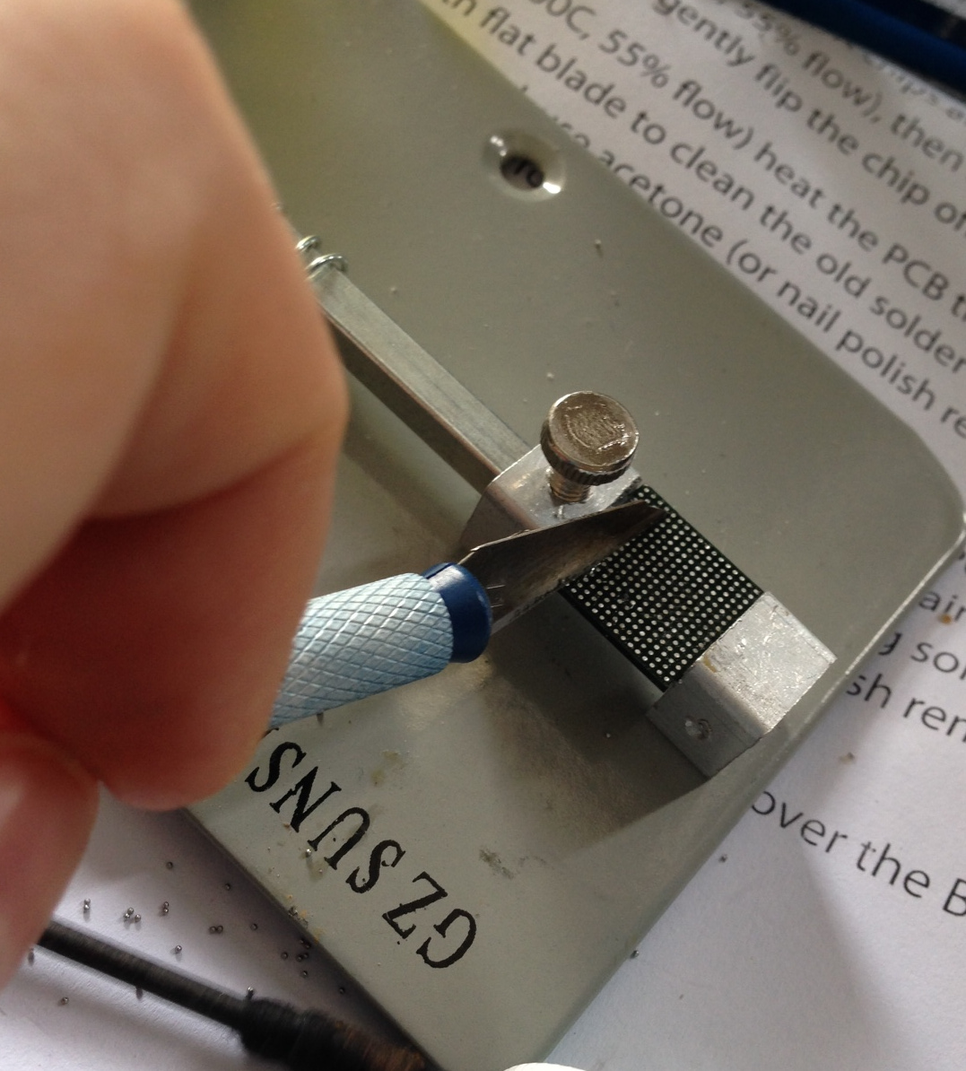
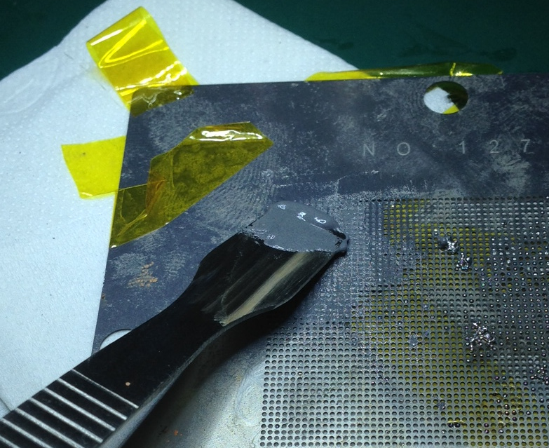
Then I set the BGA in a vice and applied heat with the hot air rework station (350degrees, flowrate 8). I gently scraped across the chip with a craft knife:

bga_cleanup

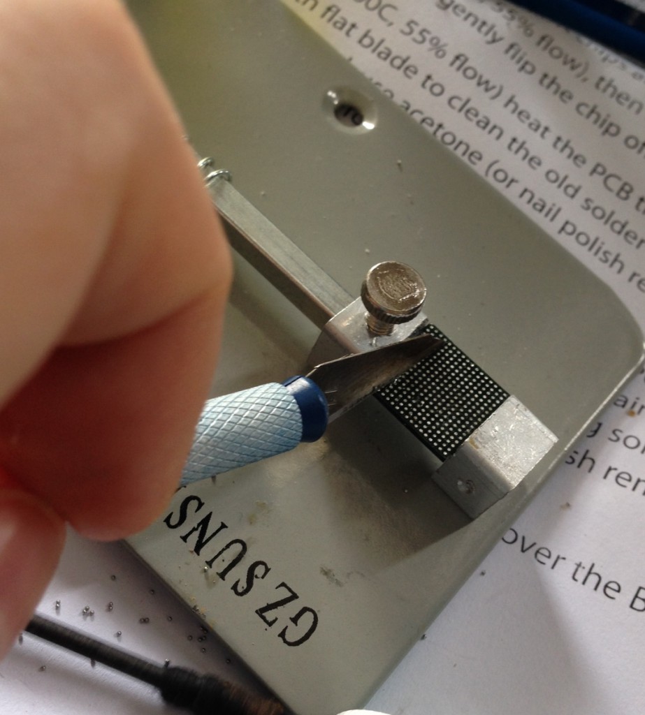
And after that went over it once more with a soldering iron. This seemed to clean things up pretty well. Though it was tempting to go over the part with some solder braid, I was concerned I’d lift pads off.

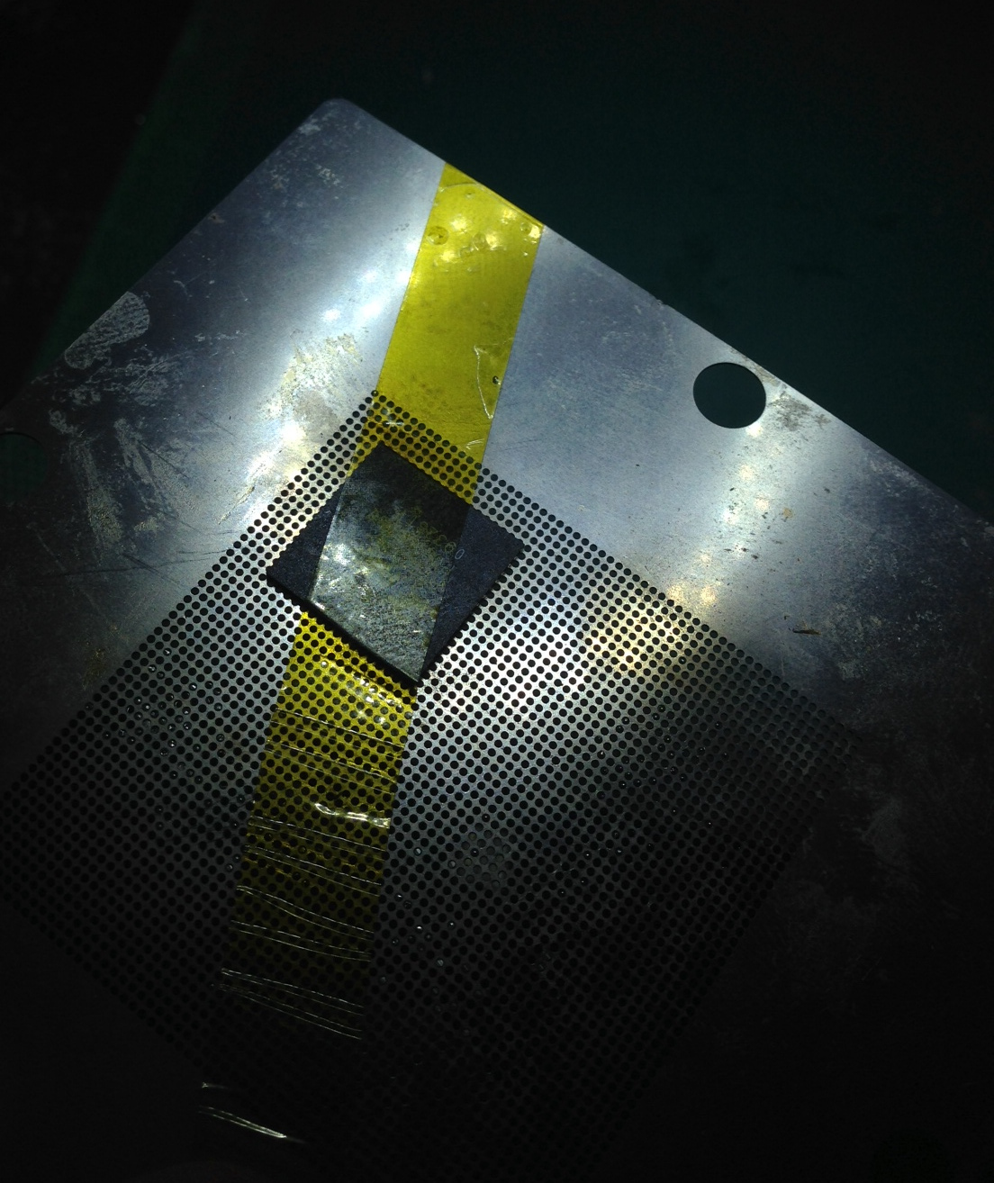
I taped the BGA part to the stencil with some off-brand kapton tape:

bga_tape2

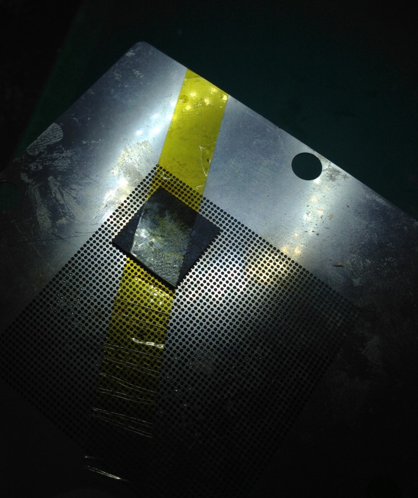
Reballing with balls – fail

BGA reballed using balls. I used 0.5mm balls (Sn63Pb37 Yue Cheng Electronics Co. Ltd). And a 0.5mm stencil. I fluxed the chip with Amtech No-clean NC-SS9 flux. As you can see this was pretty much a fail. Most of the balls just kind of stuck to stencil. They were supplied as a kit, but my guess is that actually you should use 0.45mm balls with a 0.5stencil? If you know please comment.

Update: I’ve heard from Akiba, that what a really need to do is force the balls through. I’ve ordered 0.45mm balls anyway but will try this at some point.

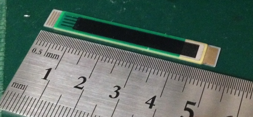
The balls that did go through looked ok:

using_balls

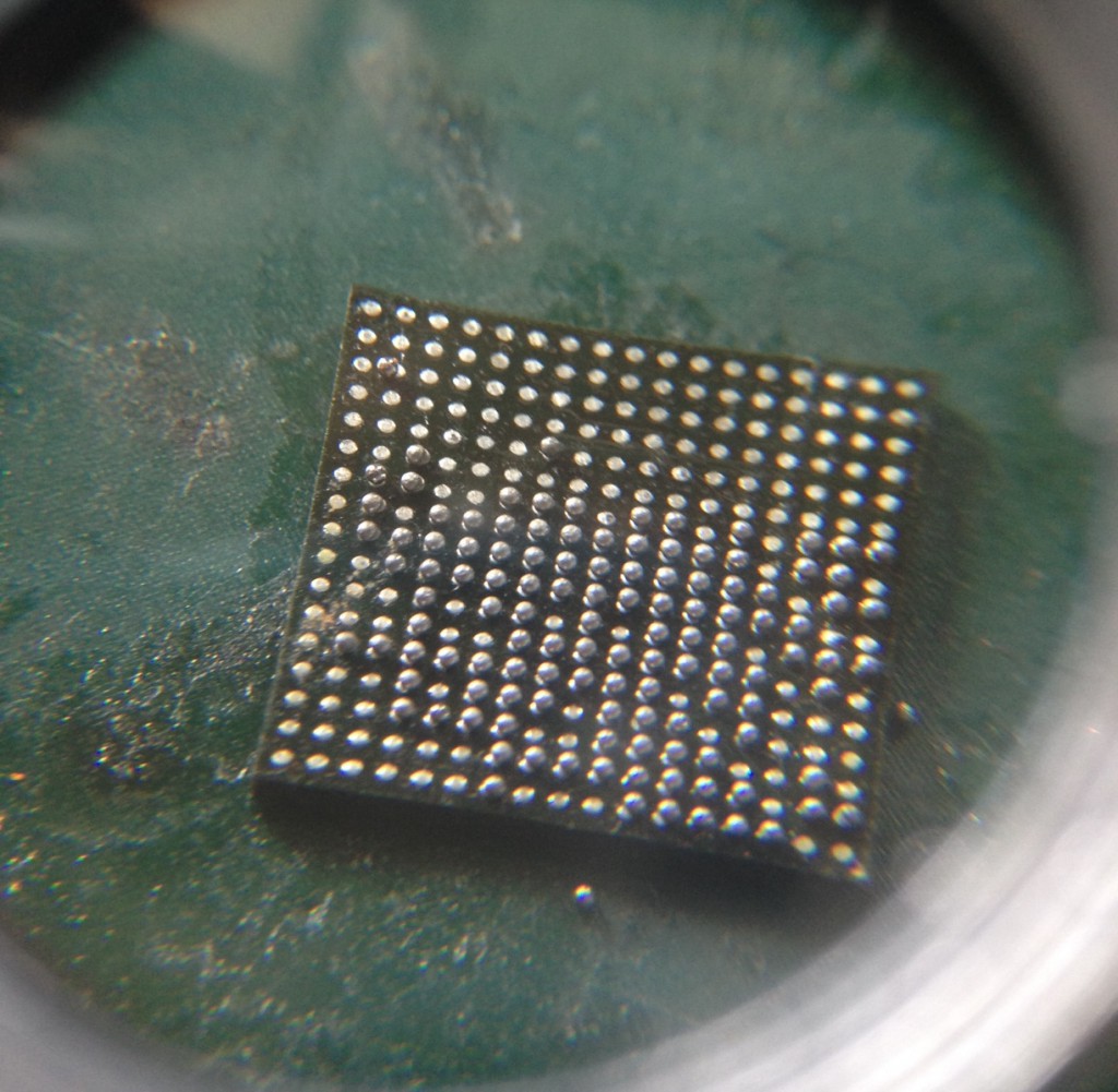
Reballing with paste – partial success

Solder paste, the paste I have is called “Classical Mechanic Solder Paste”. XG-50 Sn63/Pb37. 25-45um.

bga_paste_add

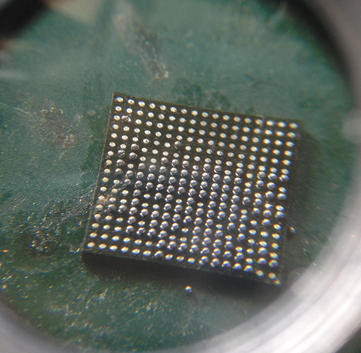
Ball made using solder paste method (I think flow rate 3.5, 200 degrees). It seems to be important to apply the flow directly downward, rather than at an angle. Also, don’t apply too much paste. Clean off excess with a Q-tip, but it’s likely excess paste will smear under the stencil anyway so you want to avoid applying too much.

bga_paste

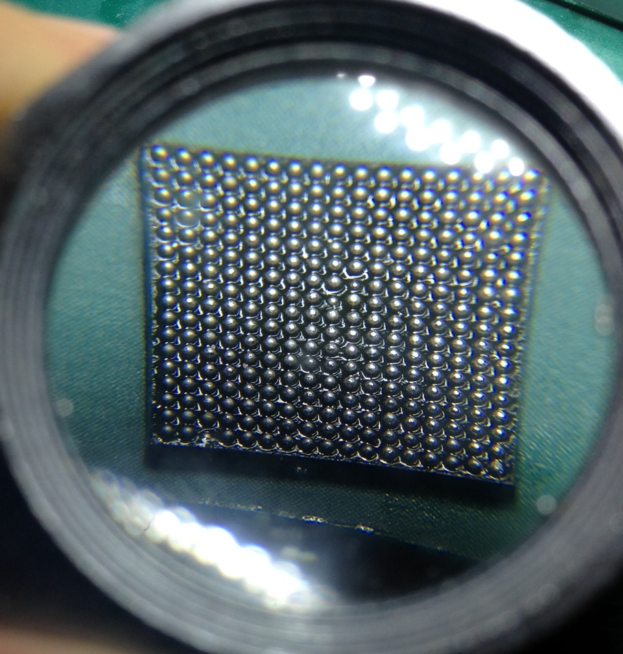
As you can see a few balls are missing. Looking at the picture again, I think the ball sizes are a bit inconsistant as well. I decided to place it anyway, the unballed pins are unused, and I figured it would be interesting to try the whole process.

The board was plated (ENIG). I used the above AMTECH flux and spread this around with the rework station (300degrees IIRC). Then applied the above paste to tin. Cleaned with flux cleaner (goot BS-R20B), refluxed, tinned. Finally left a layer of flux on the board. Then placed the chip, spent way too much time trying to get it aligned properly.

I used a flow rate of 3.5 at 350 degrees to solder the part. I tapped the board and nudged the chip a bit which I’ve heard helps the chip align.

bga_final

Everything looks good up a loupe. But I’ve yet to test it!

OpAmp as a voltage regulator

2.5v

I was trying to understand the above schematic, which came from the LT342L service manual. It’s the circuit that drives the 2.5 and 3.3v rails on the main (cpu) board. I was confused as to why an opamp was used here, rather than a voltage regulator, and exactly how the circuit was working.

So I posed my question on the Electrical Engineering Stackexchange site and received an answer in minutes.

Covering the 2.5v rail. The circuit starts with R135 and R136, this is a simple voltage divider. It divides the 5v rail in half to give a 2.5v reference. This isn’t used to drive the 2.5v rail directly as the output would be highly load dependent.

The opamp however, does not consume any current and effectively presents no load so our 2.5v will be stable. The opamp is supplied by the 12v rail. It’s implemented in a non-inverting configuration. The output of the opamp drives a MOSFET, which in turn allows current to flow to the 2.5v output. It also connects back into the non-inverting input. This opamp therefore adjusts it’s output to the MOSFET such that 2.5v is allowed to flow through the MOSFET, thereby matching the voltage on the inverting input.

I don’t fully understand the purpose of R138, if anyone knows please leave a comment!

My other question was why do use an opamp at all, rather than a voltage regulator? It seems the reason might be that a regulator designed to work with the required load, at low drop out is unlikely to be available. The fact that you have a 12v rail you can drive the opamp from helps a lot, as it gives you a lot more headroom with which to drive the MOSFET, you don’t need to worry about being too close to the 5v rail voltage. In this case, the MOSFET can source up to 20Amps which is higher than the low drop out regulators generally available are capable of. The design also offers some flexibility, in that if you only need to drive small loads, the MOSFET can be removed and the opamp can drive the rail directly.

Service manual here: LeCroy-5680

Bending Piezo Actuator

bending_piezo

I’ve been playing around with these Piezo actuators which come from pantpiezo (model number QDTE52-7.0-0.77-1). Bendable Piezo actuators offer deflection in the millimeter range at low force. The ones I have appear to be bimorphic so you need to apply an opposite voltage to each side. The video below is with a 100v supply, current draw seems to be < 1mA. From my reading of the specs they should be able to produce a deflection of ~1.2mm with a 200v drive voltage. However even with the 100v used below you can still clearly see the deflection:

Here a link to the part: here