I’ve continued to do some work with the DU530 (see previously blog posts).
I decided to see if I could drive the grating motor and register the spectra from a CFL light through the grating.
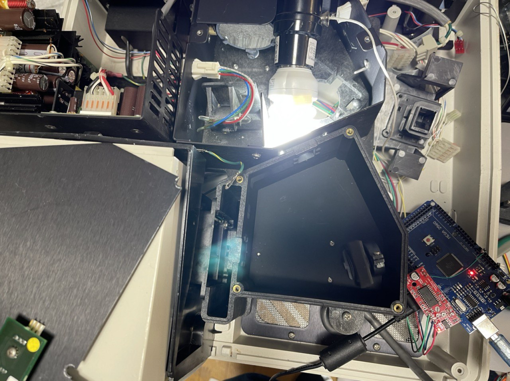
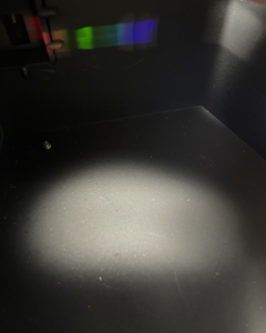
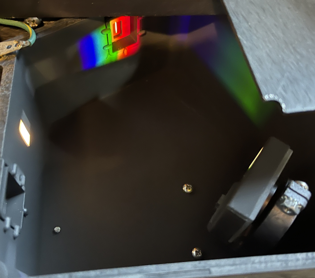
As shown above I used an EasyDriver and Arduino to drive the stepper. This showed some slipping (using a 200ms square wave generated from the Arduino to drive the step input). The CFL bulb was just jammed into the lamp box. You can fairly easily see the spectra coming out the grating:
I then registered the output of the far side photodiode using a 10M gain transimpedance amplifier. I continuously ran the stepper and monitored the output on a scope:
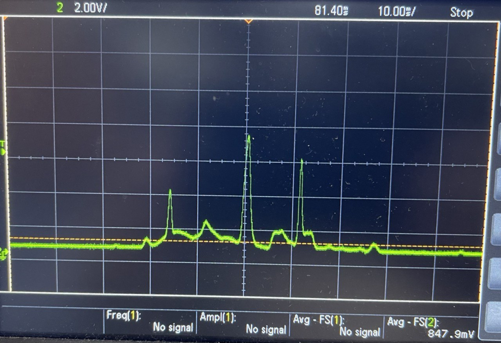
Spectra recorded on my scope
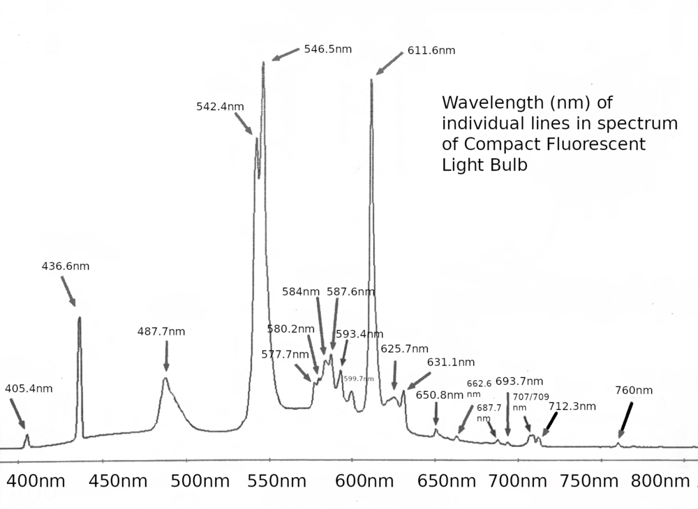
This matches the spectra published online extremely well, though the resolution is limited in the scope recording:
Obvious next step would be to record the output with an ADC/microcontroller, this would let me do slower scans. I’m also concerned that the motor is occasionally slipping, which suggests I might want to review the stepper driver…
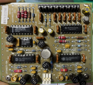
I wanted to do some basic experiments with the DU 530 UV-Vis Photospectrometer (see previous post) photodiode amplifier. In particular I wanted to confirm that they were running the diodes unbiased. I could have reassembled the unit and checked voltages, but I decided to test the photodiode board in isolation instead.
The board contains two seemingly identical (aside from the feedback resistor, the other uses a 180K instead of 1.5M) transimpedance amplifier circuits:
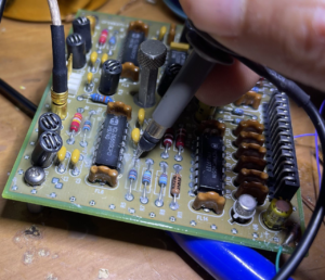
I was able to power up the opamps with +/- 10V. V- on pin 13 of the header, V+ on pin 9. I connected ground directly to the ground plain on the top of the board. By inputting a test signal (function generator output through a 100M resistor) I was able to measure low frequency current with the amplifier. The bandwidth seem very limited (few 100Hz?) but I didn’t accuracy characterize the board, and in any case things were quite noisy as I wasn’t using any shielding.
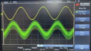
But the output was clean enough to get a rough sense of what was going on (and was as expected, inverted):
12Vpp input going through 100M resistor and out though ICL7650 in TIA configuration (~1.5M feedback resistor)
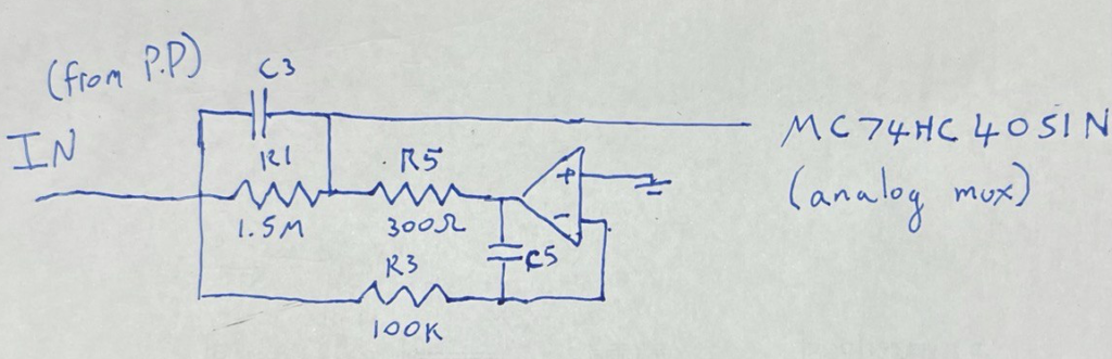
There are a few differences between the layout here and the basic transimpedance layout. R1 seems to be providing the bulk of the gain, C3 should limit peaking. Don’t fully understand why R3 and R5 are required. The output from the amplifier heads out to an analog mux. The board has 3 opamps (one for each photodiode, and IIRC there’s a header which connects to a temperature sensor). So this mux no doubt selects the opamp output to go to the header. From looking at the main PCB, it seemed like pin 14 went to the ADC on the main board. But I have no plans to further investigate this side of the circuit at this point.
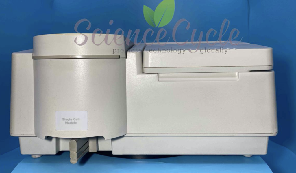
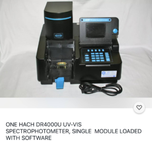
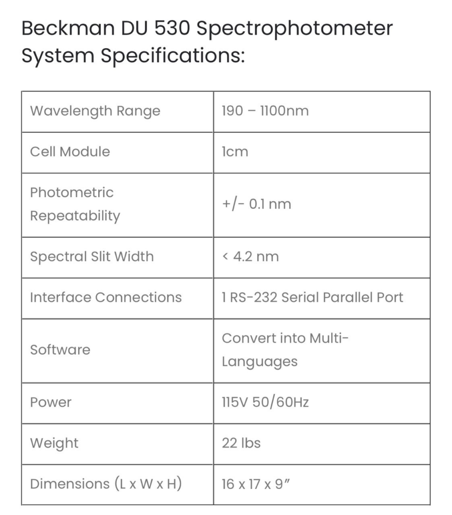
This post contains various notes on the DU530 Photospectrometer, it’s incomplete as my unit is not functioning, but never the less, my notes are here for future reference and in case they are of some use. As far as I can tell the DU 500 series is a rebadged Hach DR4000U, many of the PCBs are marked “Hach” which further supports this. And the Hach instrument looks very similar, though in stylish black:
The Hach DR4000 appears be very similar to the DU 500 Series
This is helpful, as while I’ve not been able to find a 500 Series manual online, there however a manual for the DR4000:
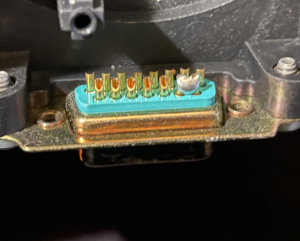
The DU 530 contains two light sources a small visible light lamp and a Deuterium UV lamp. This is model L2D2 and uses a 3 pin connector. The instrument appears to supply this with 12V. On my unit the Deuterium lamp appears to have failed. The unit will Pass all tests except the wavelength calibration. The unit will pass all other tests even without the lamp connected. The failure code on my unit is “24: Monochromator”.
As far as I can tell, the power on calibration doesn’t appear to try and power up the Deuterium lamp, which seems odd. It could be briefly powering the bulb and detecting a short/no current draw perhaps. It does seem to ramp up to ~600mV a few times so prehaps it’s checking the lamp resistance first. However when using the diagnostic mode (below) to fire up the lamp, it just goes straight to 12v…
It’s possible to enter a diagnostic mode when tests fail. You will be prompted for a “Service code”, after much experimentation this appears to be 3210, at least this is the case on my unit. This will let you enter a “System Check” menu. In this menu you can select various tests, for example to test motors, the keypad and display. By pressing the “SETUP” key on the keypad you can enter another menu. In this menu you can fire up the Deuterium lamp.
Overall the instrument hardware seems pretty serviceable. Only three Phillips screws hold the cover on, the keypad and some electronics are attached to the case, but cables are long enough to allow operation with the cover removed and placed to one side.
The instrument will pass all tests up to Lamp Alignment without any lamps installed. Lamp alignment will pass using only the visible lamp (and I suspect if there’s no issue all tests will pass using the visible lamp only). The instrument doesn’t seem to have anything to detect if the lamps are disconnected (other than the fact that wavelength/alignment tests will fail).
Unfortunately, I’ve not been able to find a user or service manual for the instrument. Though manuals for similar instruments are below (600 and 700 series).
This post has some information on error code 24: https://www.labwrench.com/thread/160951/refused-calibration
“Typically, an error code 24 required a reinitialization of the spectrophotometer using a special software program and cell holder module. This can only be done by a service engineer that actually has the software and cell holder. Before going that route you might check the condition of your visible lamp and how clean your optics are. If your visible lamp’s envelope is darkened and or bubbled, replace it and try again.”
An open source program to read serial output is available here: https://github.com/Schallaven/Beckman-DU-520-reader (I have not tested this). With the tests failing, I’ve not been able to see any serial output from the unit during boot. I wonder if there’s some way to enable a serial debug interface…
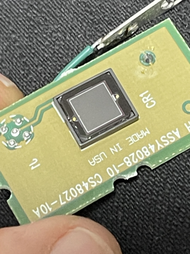
Photodiode (output side): Best I can tell is this is a S227-1010BQ, which specs sensitivity down to 190nm. Datasheet here: https://www.hamamatsu.com/resources/pdf/ssd/s1227_series_kspd1036e.pdf
Further notes on the photodiode amplifier circuit are here.
Tested the photodiodes with a transimpedance amplifier, un-biased:
Under ambient light the small (input side) photodiode outputs about 0uA and >450uA under illumination.
Under ambient light the large (output side) photodiode outputs about 20uA and > 450uA under illumination.
Steppers used on the lamp alignment mirror and grating are Oriental Motor, Vexta PX243M-03AA-C6 and PX243M-03AA-C9, 2-phase 0.9deg/step. DC 12V 0.3A. Datasheet: https://www.orientalmotor.com/products/pdfs/opmanuals/HM-601-17JECK.pdf
Pics of various parts of the instrument below:
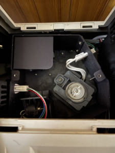
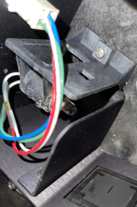
Lamp box, easily accessed without disassembly. The large lamp is the Deuterium lamp. The visible lamp is to the bottom left.
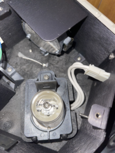
Here you can see the lamp alignment mirror (which is motorized). I assume this combines the emissions from both lamps.
The smaller visible light lamp
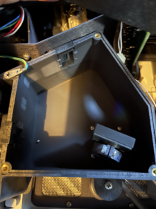
This is the monochromater block, the diffraction grating is to the lower right. The top cover of this block has what I believe is a Hall effect sensor attached. I assume this is for determining the filter wheel position (though it seems relatively far from the filter wheel).
Pretty rainbows
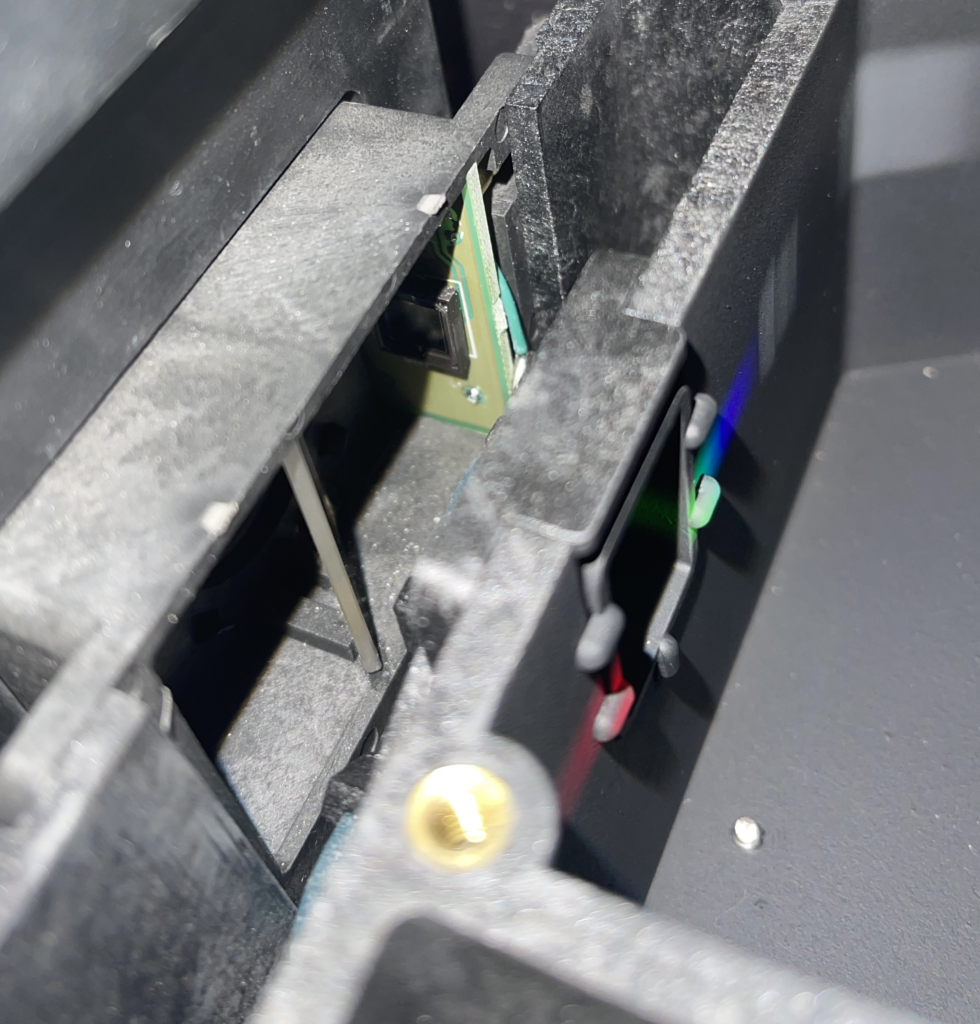
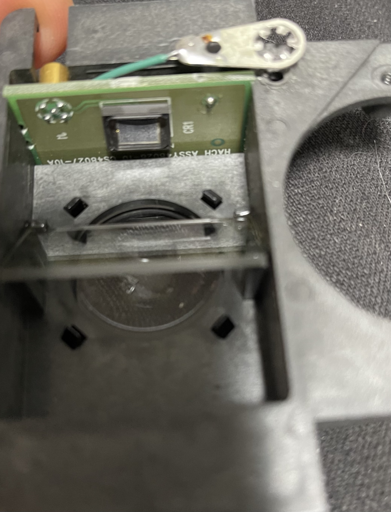
There seems to be a beam splitter and photodiode on the output of the monochromator, there’s a filter wheel here too.
There’s a connector on the cell module, which the instrument uses to detect it’s presence (and I assume type), just a short between a couple of pins…
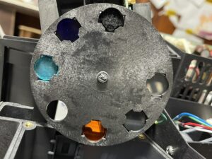
Filter wheel, many of the filters are cloudy which I suspect is the main problem with this instrument…
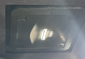
Lamp image of the slit post lamp alignment. I assume it’s essentially projecting the filament image on the slit?
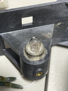
Visible light lamp, it seems to be glued into the carrier.
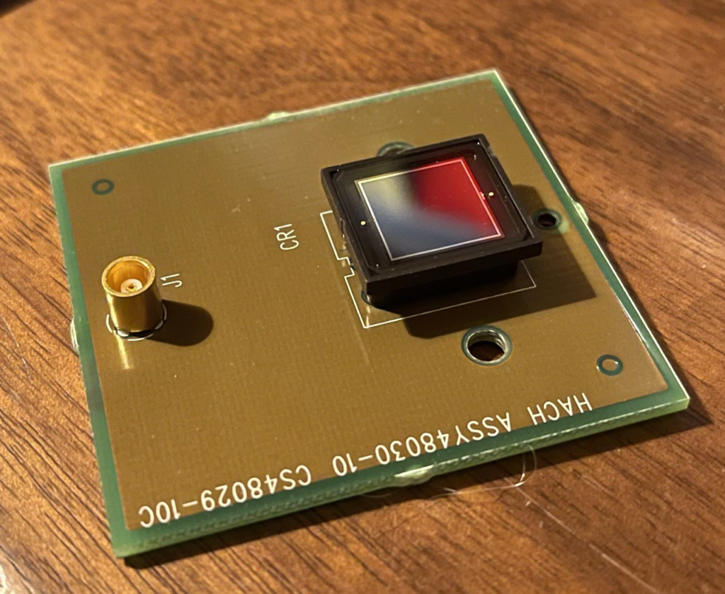
Photodiode from the “output” side of the cuvette. Best I can tell is this is a S1227-1010BQ: https://www.hamamatsu.com/resources/pdf/ssd/s1227_series_kspd1036e.pdf
The smaller (cuvette input side) photodiode and beam splitter.
My name is Nava Whiteford. I’ve worked for a few sequencing companies. I have equity in a few sequencing companies based on my previous employment (I try to be unbiased in my posts). You can contact me at: [email protected]