Moving a 1Kg Static Load
 So… here’s the thing. While I really like motors, My preference is generally to those with nanometer resolution, and where the loads are pretty inconsequential. The other day I was looking at a project where we needed to move a few kilograms through a couple of meters.
All I had was a random (reasonably high torque, but not great) stepper motor and an easydriver. This completely failed to solve the problem.
So, I’ve been trying to get geared (haha, funny guy!) up to solve a range of problems in motion such that when the next project comes along I have a set of motors I can throw at the problem.
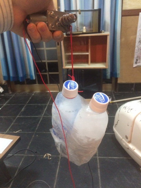
To that end I’ve been looking at geared DC motors and H-bridges. The picture to the right is my current test setup and this post just briefly documents what I have at the moment.
The 2 bottles of (frozen) water there weight about a kilogram. The motor I’m using incorporates a worm gear. It’s a 12V 100RPM motor, which I picked up on eBay.
When driving this from a bench supply it uses about 1.2A moving 1Kg at about 5cm/s.
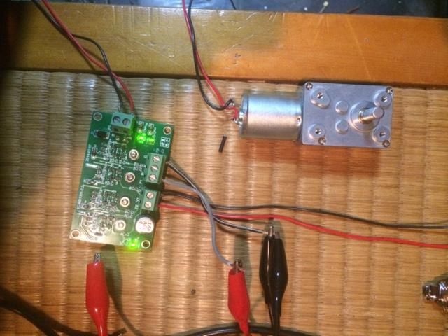
That’s great but obviously if I’m going to do something useful with this I need to be able to rotate the actuator in both direction. For this I need an H-bridge. I’ve picked up a couple the one below (again from eBay) is the one I’ve tested:
It’s pretty simple, attach your power supply (set at 12V) to the drive power input pins. Attach the motor to the “drive output” pins (doesn’t really matter which way round). And then supply the control signals on the input.
 The control signals use PWM to moderate the power supplied to the motor. The drive frequency isn’t hugely critical, but the duty of the square wave is. The direction pin then changes the direction of the rotation (using the H-bridge to reverse the polarity of the supply across out output pins).
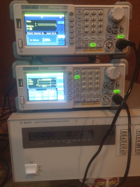
The control signal is (I assume, because that’s what I used) a 5V input. You can easily generate this an Arduino or similar microcontroller board. But for the purposes of testing I used a signal generator. This PWM signal is applied to the “P” pin.
I couldn’t push my generator beyond an 80% duty cycle. But at 80% the motor consumed about 500mA underload. About half what it was from the PSU. It still seemed to move the load without issue but I should probably figure out what’s going on here. To invert the direction you need to apply a voltage to the “D” pin. When reversing direction you also appear to need to invert the duty cycle to maintain the same speed (80% becomes 20%).
That’s pretty much it for now. The picture to the right shows the function generator settings (I used another function generator to generate the 5v direction input because… I happened to have 2 function generators knocking around).
Anyway… that’s about it for now. I’m comfortable that I’m slowly acquiring the tools needed for the next motion project that pops up and will hopefully be able to knock together prototypes of such systems more quickly in the future.
