I was offered a broken WPSD5 Surround Sound system and of course snapped it up. A couple of weeks back someone also offered me a working one but I turned it down. Positioning all those speakers felt like too much for an audio-luddite like me. But a broken one… well that’s an adventure!
While economically un-viable repairing broken consumer electronics gives an interesting insight into the design discussions taken. And for someone like myself who isn’t an experienced EE, wandering through the schematics teaches me all sorts of things. Gratifyingly a service manual is available with both detailed schematics and a overall block diagram:
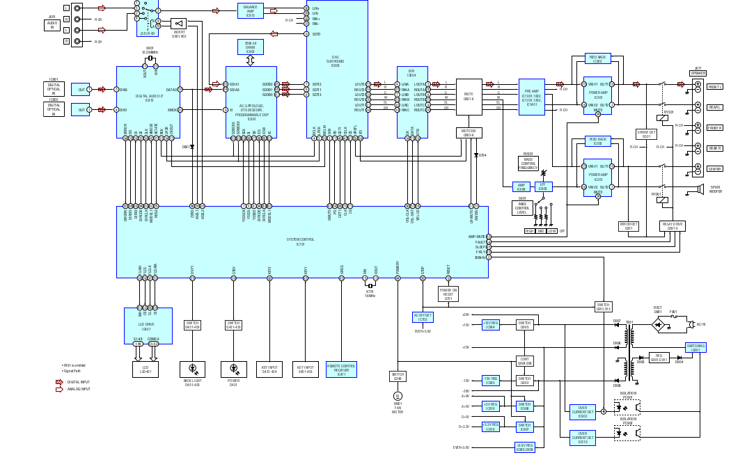 Worryingly the digital side is built about a proprietary microcontroller (IC701). The microcontroller is powered by EVER+5.6V which comes off the main power supply and is always up. Other supply voltages (for the analogue section) are brought up by the microcontroller on soft power on.
The microcontroller itself however doesn’t do very much, it just brings up the system and controls the surround sound DAC. The DAC is an AK4527, for which a datasheet is readily available. This is a fun part, it’s a I2C controlled surround sound synthesizer. It includes ADCs to sample analogue input or can also accept digital signals (S/PDIF via some external ICs). Analogue signals head out of this IC and out of the digital board toward the analogue section.
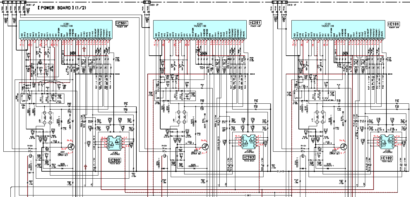
On the analogue board we find 3 TA2022 power amplifiers. These are 2 channel 90W “class-T” amplifiers. Class-T is Tripaths proprietary, switching, class-D amplifier implementation. The TA2020 from this series was listed as one of the 25 microchips that shook the world. It was my first time encountering class-D amps and it was interesting reviewing this part of the design. A datasheet for the ta2022 is also available, and TA2022 modules can be found on eBay easily for about 15USD. They look like fun modules and I’ve seen a number of amateur projects using them.
So… on my system the fault signal was being asserted, by this funky transistor network:
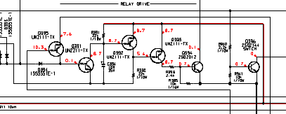 That signaled a fault to the microcontroller, which in turn stopped the main powersupply from coming up and didn’t enable the relays on the speaker outputs so you wouldn’t be able to hear anything anyway. In order to debug further I need to get the amplifiers to come up. I removed the digital board and started digging around.
First of all, you can pull pin 16 (POWER) on CN123 to +4.7V DIRECT (which is also always up). That switches IC906 on. This is a regulator (datasheet) which generates a bunch of supply voltages. I then shorted Q394 which is the transistor controlling the output relays. The amplifiers where still muted (controlled via AMP-MUTE) so I pulled AMP-MUTE high (I think using +4.7V DIRECT again) to turn them out.
In debugging the system I found that 2 of the amplifier ICs weren’t coming up. The TA2022s have built in fault detection and 2 of them were muting themselves. The layout of the 3 TA2022s the largely identical, IC301 however does also generate a reference signal that is fed to the other two:
Strangely the system doesn’t used the HMUTE signal from the TA2022s but has additional fault detection circuitry, and this was causing the fault signal that was being sent to the microcontroller. The TA2022s own fault detection circuitry was also firing however. This is basically where my debugging stopped. I would likely continue by replacing the TA2022s, but it wasn’t worth it for me.
Now… what I’ve actually been wanting is a cheap 2 channel stereo speaker system. So I hacked a 3.5mm stereo jack on to the input of the analogue board and am using the surround sound system as a stereo speaker set. I’m just using a couple of the satellite speakers. This is probably a pretty awful thing to do, I’d guess they don’t produce low frequencies particularly well, but it sounds fine to me and is and order of magnitude better than my laptop speakers so I’m happy… I also had an interesting adventure and learned a lot about how consumer Hi-Fi equipment is put together.

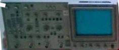 This makes little sense to me. I really don’t know of any scopes with a CRT on the right hand side. Maybe someone can point one out? But I’m pretty confused here (based on the fact that the Nike swipe is also fipped, I’d guess the image is mirrored but I’m going to run with this..).