AD5791 Shield First Rev
 I received the AD5791 Arduino shield PCBs from the fab today. And built them up. There are a number of revisions that I’ll need to make:
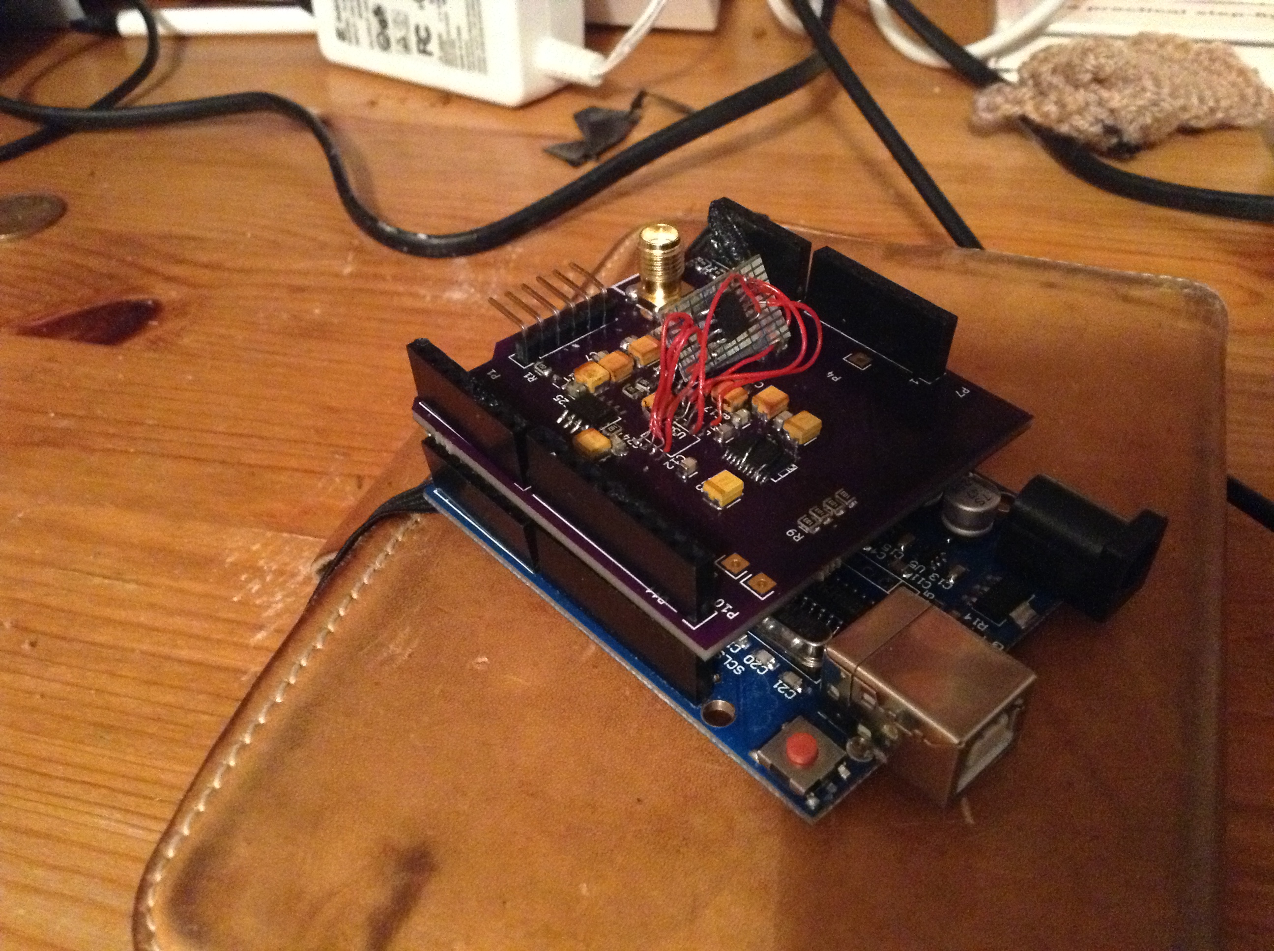
- The holes on the SMA connector are too small.
- AGND and DGND are not tied near the AD5791
- The Pads on U1,U2 and U3 are too far apart for my liking.
- U3 has a via on a pad which I don’t like
- The Tantalum caps should have polarity markings.
- U5 silk marking is unclear (actually a lot of the silk is unclear)
- C23 footprint is wrong cap type
- C5 has the wrong polarity in the schematic
- pin 7 on U1 is NC. It should be connected to the feedback resistor. I blame Kicad.
- pin 5&6 and 2&3 on U3 are the wrong way round (can’t blame Kicad for that!).
- U1B is wrong in the schematic (inverting/non-inverting pins incorrectly labeled) but the layout is correct.
I patched the board and it appears to work. I’m slightly concerned out the output buffer opamp. For some reason it seems to have gain, which causes issues. A new rev is required anyway…