Tank Circuits
In preparation for learning more about the Colpitts Oscillator, I wanted to understand Tank circuits a bit better. A Simple Tank (or LC) circuit is simple a Inductor and a capacitor in parallel:

The tank circuit is useful because it results in a resonance. If you charge the capacitor and then remove power, the capacitor will discharge through the inductor. As the charge passes through the inductor it will build up a magnetic field, storing the energy. When the capacitor finishes discharging the field will collapse. This will result in a current, which will charge the other side of the capacitor, beginning the process again. The process will continue producing a frequency determined by the discharge rate of the capacitor and inductor. This frequency is given by the equation:
![]()
Wikipedia has a great animation of the process, replicated here (and slowed down slightly):
In a perfect world the resonance would keep going for ever, however losses due to the inductor resistance among other things means the resonance doesn’t last very long. You can see it on a scope however. To show this I connected a capacitor and inductor (22nF and 10uH) in parallel. The polarity will be reversing, so it’s likely unwise to use an electrolytic:
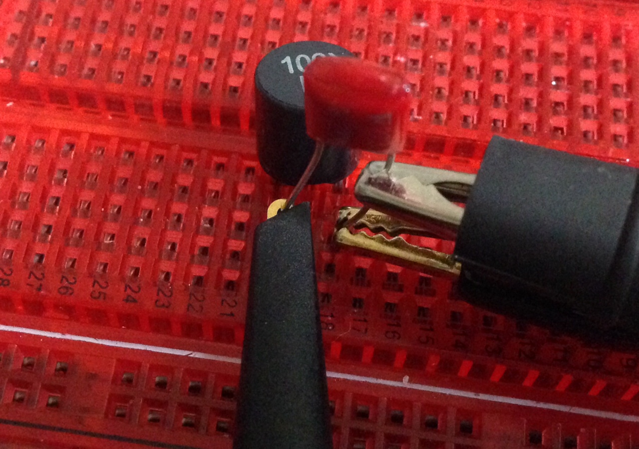
I then connected the power and set my scope to take a single shot, then removed the power. The result was the following trace:
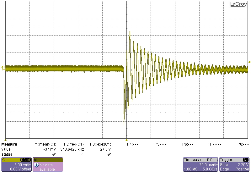
Which as predicted by the equation above is ~340Khz.