Phase Shift Oscillator
Today I’ve been trying to understand the phase-shift oscillator. In order to understand the phase-shift oscillator, you first need to understand the phase-shift caused by a capacitor!
The figure below shows a single capacitor causing a phase shift:
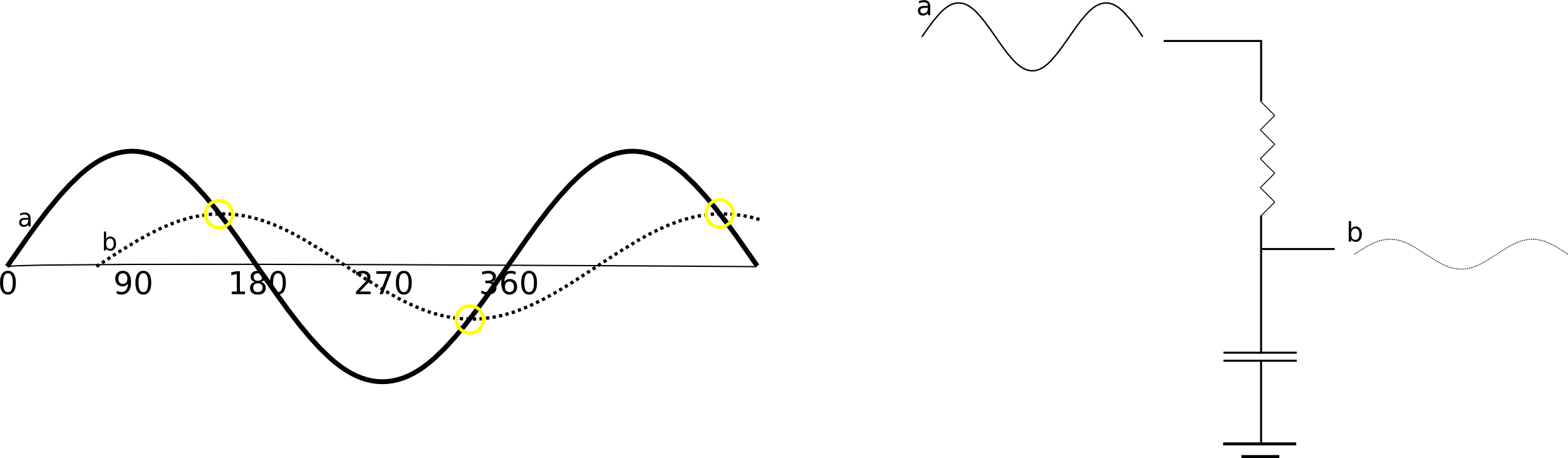
It took me a little while to understand why a capacitor in this configuration causes a voltage phase shift. However, fundamentally the charging of the capacitor causes a lag, it take the capacitor a while to “catch up” with the current voltage, so it appears to lag behind the input. This means the amount shifted will depend on the capacity of the capacitor (how long it takes the capacitor to get up to full voltage). The capacitor can only lag behind the current voltage. This means that you can shift the phase by at most 90 degrees. Any more that this and the capacitor would be fighting the input voltage, rather than approaching it’s current value. The phase-shift will also always cause some attenuation, that the capacitor is trying to “catch up” with the current voltage, but never quit getting there. It’s worth note that if you overlay the original sine wave and the shifted version, the shifted wave will always cross the input at the shifted versions maximum voltage. You can therefore see the relationship between attenuation and the degree of phase-shift.
Hopefully that helps explain phase-shift a little. For a phase-shift oscillator we use this characteristic to generate an oscillation.
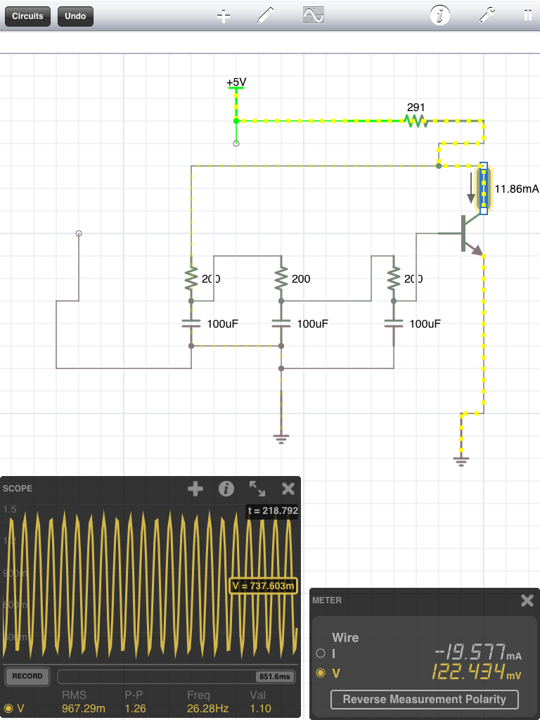
Here’s the phase-shift oscillator circuit, there are different configurations, but this is the one we’re going to talk about:
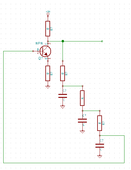
I’ve drawn the schematic so the 3 phase-shift resistor/capacitors line up. Each set will shift the phase of the input ~60 degrees. This results in a 180 degree shift. Remember because we can only shift by less than 90 at a time we need 3 sets of capacitors. We’ll also be significantly attenuating the input with each shift.
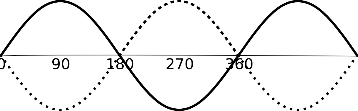
The output of the phase-shift network in this oscillators drives the input to an amplifier (in this case a transistor) in a feedback loop. But why do we want to shift by 180 degrees? Well, if we shift a sine wave by 180 degrees we’ll end up with the exact opposite of our signal. The NPN transistor we’re using is in an inverting configuration (you might want to read my other post about that), this effectively gives another 180degrees of shift. The result is a resonance at a frequency determined by the phase-shift network resulting in an oscillation.
Here’s a simulation of the phase-shift circuit shown above:
You can also download the file for iCircuit here.
I built the circuit up using an 2N2222 and the approximate values in the simulation above:

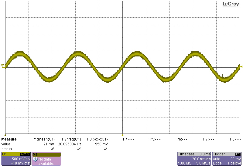
It worked pretty well, output a 20Hz sine wave which is approximately as expected from the simulation:
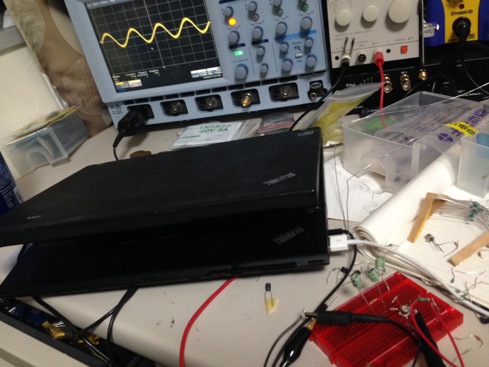
Here’s a clearer picture of the trace: