Driving a tiny stepper on an Arduino (without a driver!)

tiny_stepper2

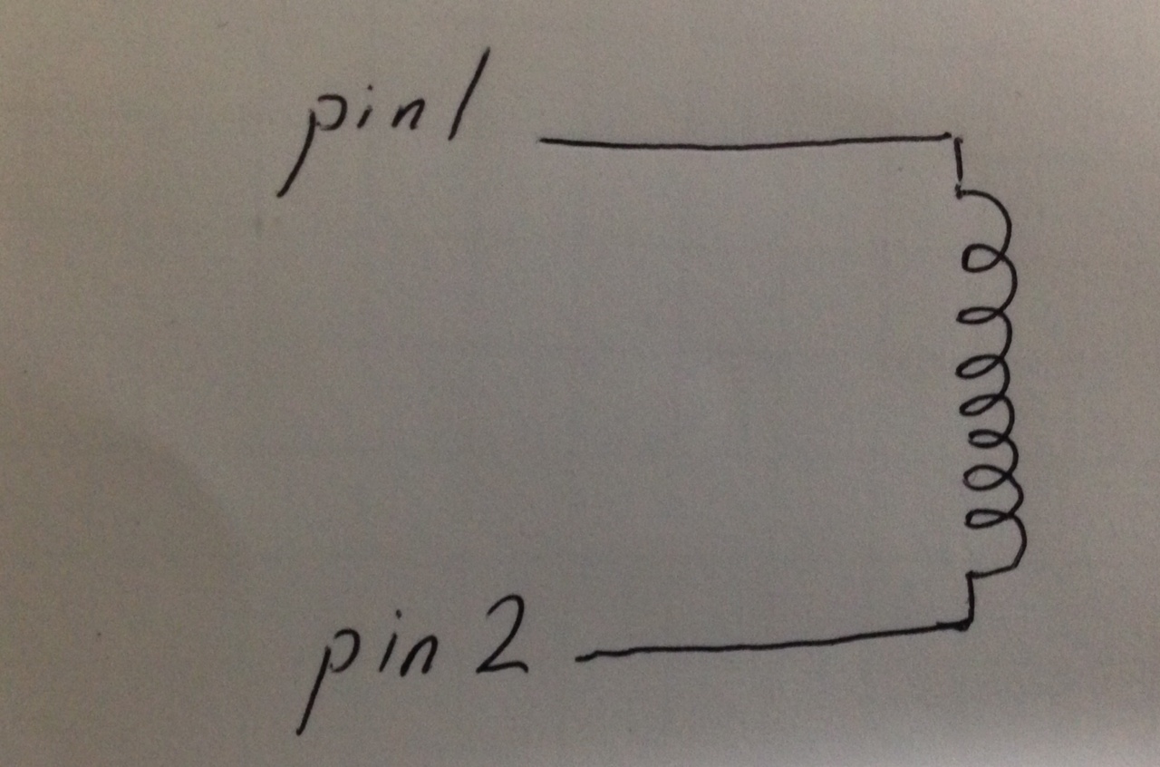
I had this stepper knocking around in my junk draw. And figured it would be interesting to hook it up to an Arduino and play around with. Probing the motor showed it was a Bipolar stepper (no center tap) with 40Ohm windings.

Not really wanting to waste an EasyDriver or motor shield on it I was thinking about what else I could do. Another option was to use a ULN2003 which I’ve done before though it’s slightly problematic driving bipolar steppers with them.

In the end I figured the motor is tiny, and unlikely to require much current. The Arduino itself can source and sink up to 40mA so why not try driving it directly!

tiny_stepper1

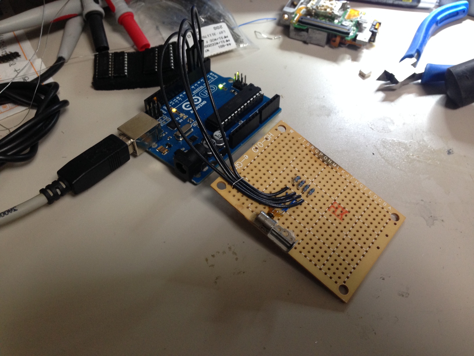
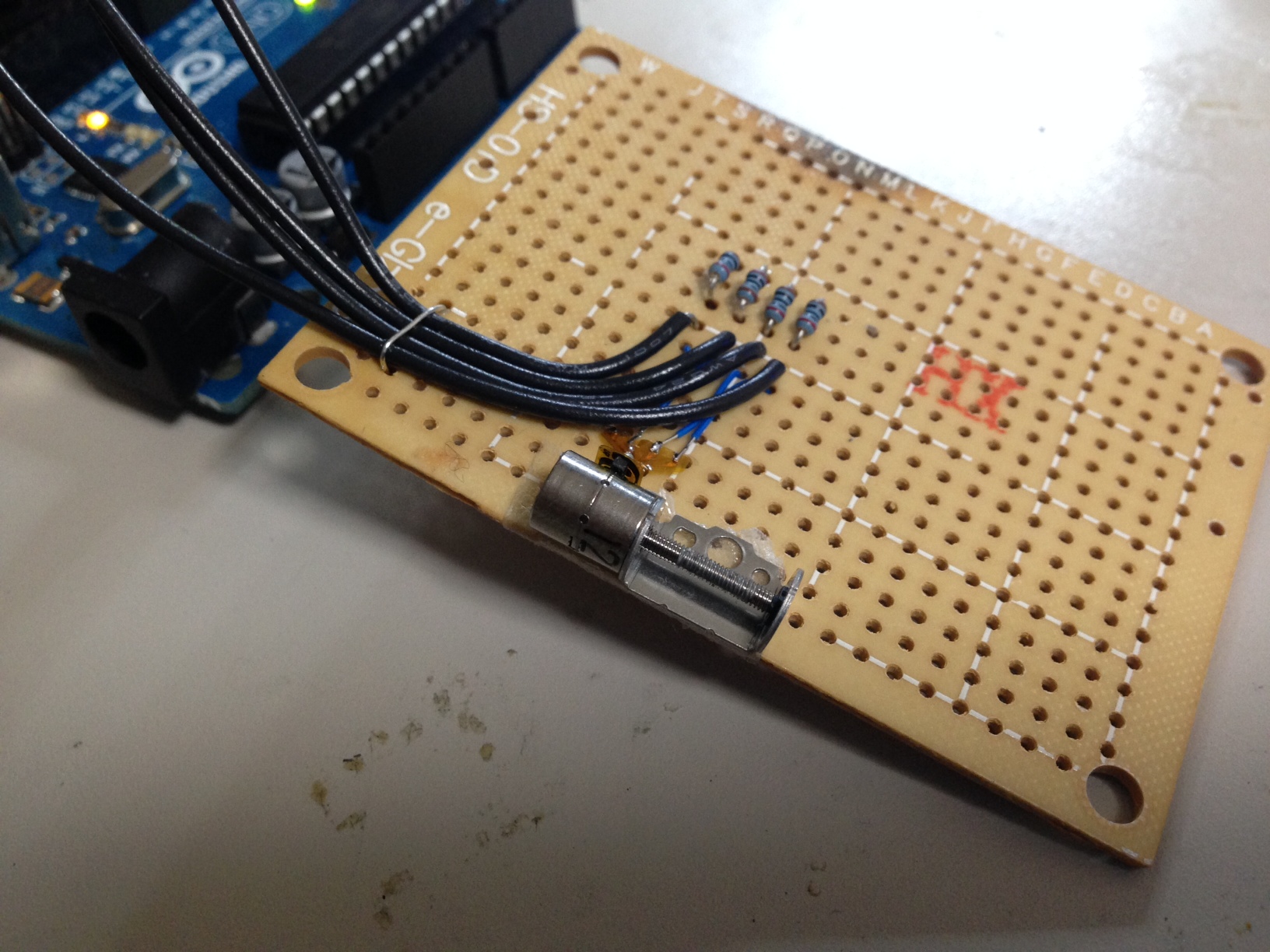
Four Arduino pins are used, a pair for each winding on the stepper:

tinystep_dia

I then used code adapted from elabz to drive the stepper (listing in the notes below). I should really also add some current limiting resistors, as without them I think I’ll be drawing about 100mA and am liable to kill my Arduino if I keep running it in this configuration. Video below shows the stepper working and describes the setup:

I really like these parts, and I’ll have to think of a project to use them in. I’ve been interested in imaging IC dies and these stepper could be used to make a cute little low profile XY stage with just enough torque to move a die around.

Notes


int motorPin1=2;
int motorPin2=3;
int motorPin3=4;
int motorPin4=5;

void setup() {
  // set the digital pin as output:
  pinMode(motorPin1, OUTPUT);      
  pinMode(motorPin2, OUTPUT);      
  pinMode(motorPin3, OUTPUT);      
  pinMode(motorPin4, OUTPUT);
}

void loop()
{ 
  digitalWrite(motorPin1, HIGH);
  digitalWrite(motorPin2, LOW);
  digitalWrite(motorPin3, HIGH);
  digitalWrite(motorPin4, LOW);
  delay(50);
 
  digitalWrite(motorPin1, HIGH);
  digitalWrite(motorPin2, LOW);
  digitalWrite(motorPin3, HIGH);
  digitalWrite(motorPin4, HIGH);
  delay(50); 
   
  digitalWrite(motorPin1, HIGH);
  digitalWrite(motorPin2, LOW);
  digitalWrite(motorPin3, LOW);
  digitalWrite(motorPin4, HIGH);
  delay(50); 
   
  digitalWrite(motorPin1, HIGH);
  digitalWrite(motorPin2, HIGH);
  digitalWrite(motorPin3, LOW);
  digitalWrite(motorPin4, HIGH);
  delay(50);
   
  digitalWrite(motorPin1, LOW);
  digitalWrite(motorPin2, HIGH);
  digitalWrite(motorPin3, LOW);
  digitalWrite(motorPin4, HIGH);
  delay(50);
 
  digitalWrite(motorPin1, LOW);
  digitalWrite(motorPin2, HIGH);
  digitalWrite(motorPin3, HIGH);
  digitalWrite(motorPin4, HIGH);
  delay(50);
 
  digitalWrite(motorPin1, LOW);
  digitalWrite(motorPin2, HIGH);
  digitalWrite(motorPin3, HIGH);
  digitalWrite(motorPin4, LOW);
  delay(50);
   
  digitalWrite(motorPin1, HIGH);
  digitalWrite(motorPin2, HIGH);
  digitalWrite(motorPin3, HIGH);
  digitalWrite(motorPin4, LOW);
  delay(50); 
}

Stepper motors notes

image

Best Video I’ve seen on the basics of what’s going on in a stepper motor (he has a thick accent, but the content is great):

The take home message appears to be to understand how the poles are arranged such that the poles on the stator and electromagnets are offset slightly, so that with each step the rotor is pulled round.

After that it seems wise to investigate unipolar and bipolar configurations, as that will be one of the things you’ll encounter when setting up your steppers. As I understand it a unipolar motor uses two separate coils (or rather a single split coil, where only half is driven at any one time), and drives current in a single direction through each coil. A bipolar motor uses a single coil, the direction of the current is reversed to change polarity. Because unipolar motors just have an additional center tap, it is generally possible to drive them in both a unipolar, and bipolar configuration. Bipolar motors generally do not have a center tap, and therefore can not be driven as unipolar motors.

This is a pretty reasonable video on the topic:

As the strength of the magnetic field in an electromagnet is proportional to the current flowing through the coils, I would guess that you might want a driver that supplies constant current. However, a constant voltage over the winding resistance will give you a constant current in any case. The wikipedia page has some useful info here, the relevant part is replicated below:.


L/R driver circuits

L/R driver circuits are also referred to as constant voltage drives because a constant positive or negative voltage is applied to each winding to set the step positions. However, it is winding current, not voltage that applies torque to the stepper motor shaft. The current I in each winding is related to the applied voltage V by the winding inductance L and the winding resistance R. The resistance R determines the maximum current according to Ohm’s law I=V/R. The inductance L determines the maximum rate of change of the current in the winding according to the formula for an inductor dI/dt = V/L. Thus when controlled by an L/R drive, the maximum speed of a stepper motor is limited by its inductance since at some speed, the voltage U will be changing faster than the current I can keep up. In simple terms the rate of change of current is L / R (e.g. a 10 mH inductance with 2 ohms resistance will take 5 ms to reach approx 2/3 of maximum torque or around 24 ms to reach 99% of max torque). To obtain high torque at high speeds requires a large drive voltage with a low resistance and low inductance.

With an L/R drive it is possible to control a low voltage resistive motor with a higher voltage drive simply by adding an external resistor in series with each winding. This will waste power in the resistors, and generate heat. It is therefore considered a low performing option, albeit simple and cheap.

Chopper drive circuits

Chopper drive circuits are referred to as constant current drives because they generate a somewhat constant current in each winding rather than applying a constant voltage. On each new step, a very high voltage is applied to the winding initially. This causes the current in the winding to rise quickly since dI/dt = V/L where V is very large. The current in each winding is monitored by the controller, usually by measuring the voltage across a small sense resistor in series with each winding. When the current exceeds a specified current limit, the voltage is turned off or “chopped”, typically using power transistors. When the winding current drops below the specified limit, the voltage is turned on again. In this way, the current is held relatively constant for a particular step position. This requires additional electronics to sense winding currents, and control the switching, but it allows stepper motors to be driven with higher torque at higher speeds than L/R drives. Integrated electronics for this purpose are widely available.

This video on driving steppers in also interesting:

Read a local file into a Javascript string

I needed to grab a local file and pull it into a Javascript string, I wanted to do this without any serverside support. I hack together the following short example, the same method can be used to pull in raw files for client-side processing:

<input type="file" id="files" name="files[]" multiple />
<output id="list"></output>

<script>
  function handleFileSelect(evt) {
    var files = evt.target.files; // FileList object

    for (var i = 0, f; f = files[i]; i++) {

      var reader = new FileReader();

      // Closure to capture the file information.
      reader.onload = (function(theFile) {
        return function(e) {
          var s = String.fromCharCode.apply(null, new Uint8Array(e.target.result));
          document.write(s);
        };
      })(f);

      // Read in the file as an ArrayBuffer
      reader.readAsArrayBuffer(f);
    }
  }

  document.getElementById('files').addEventListener('change', handleFileSelect, false);
</script>

Lack of return causes abort() in Emscripten

I received the following Javascript exception from some code compiled with Emscripten. The code was working correctly as a standalone C++ program. This confused me for a while:

uncaught exception: abort() at jsStackTrace@file:///home/new/gitcode/repeatanalysis/progs/r.js:1049:7
stackTrace@file:///home/new/gitcode/progs/r.js:1066:3
abort@file:///home/new/gitcode/progs/r.js:8368:3
_llvm_trap@file:///home/new/gitcode/progs/r.js:4960:7
__Z15test_badret_auxiii [test_badret_aux(int, int, int)]@file:///home/new/gitcode/repeatanalysis/progs/r.js:8079:2
_test_badret@file:///home/new/gitcode/progs/r.js:8089:2
asm._test_badret@file:///home/new/gitcode/progs/r.js:8148:1
ccallFunc@file:///home/new/gitcode/progs/r.js:534:9
@file:///home/new/gitcode/progs/r.html:15:4

The cause was a non-void function failing to return a value. Here’s the complete example:

#include <iostream>
#include <fstream>
#include <vector>
#include "malloc.h"

using namespace std;

int test_badret_aux(int arg1,int arg2,int arg3) {
// return 0;
}

extern "C" {
int test_badret(char *inputstring);
}

int test_badret(char *inputstring) {
test_badret_aux(1,100,100);

return 0;
}

Compiled with (I tried a bunch of options):

 emcc ./r.cpp -o r.js -s EXPORTED_FUNCTIONS="['_test_badret']" -s SAFE_HEAP=1 -g -s ASSERTIONS=1

And driven with the following html:

 <!DOCTYPE html>
<html>
<body>
<script src="r.js"></script>

<script>

var mystring = "test";
var strptr = Module._malloc(mystring.length);
Module.writeAsciiToMemory(mystring, strptr);

var ret = Module.ccall('test_badret', // name of C function
  'number', // return type
  ['number'], // argument types
  [strptr]); // arguments

</script>


</body>
</html>

If I uncomment the return in the above C program, the code no longer aborts. Understandable perhaps. But seemed unusual to me. This was using Firefox (Iceweasel 31.2.0 on Debian Jessie).