December 15, 2014, 6:49 pm
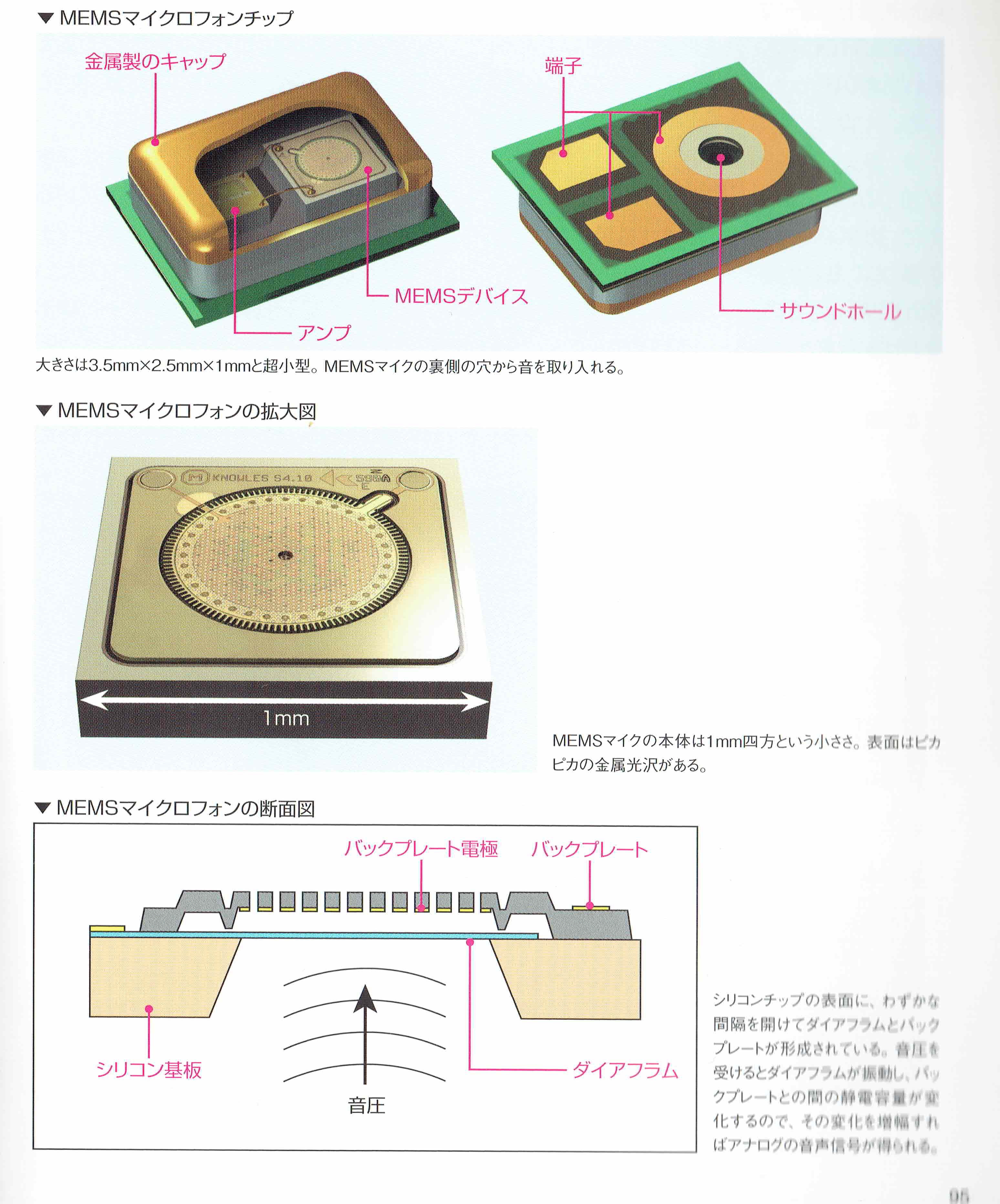
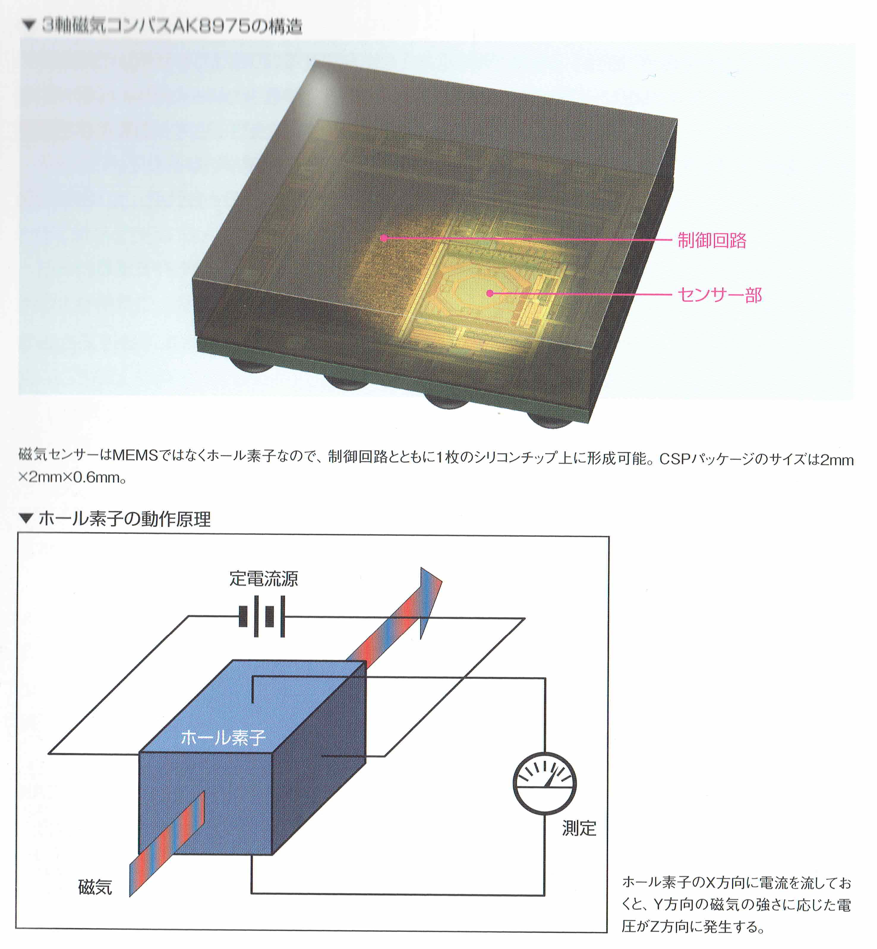
I picked up this book called “inside of iPhone” a while ago. While it’s all in Japanese, I couldn’t resist it based on the illustrations. It’s full of excellent and detailed illustrations, like those of the MEMS sensors below:

Knowles MEMS microphone
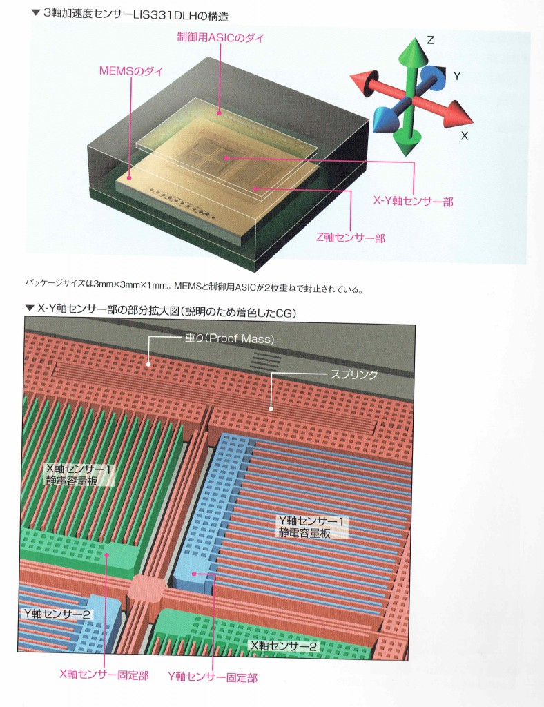
LIS331DLH, 3-axis accelerometer.
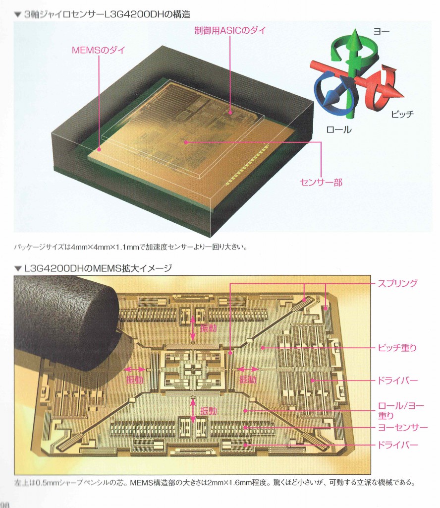
L3G4200DH Motion Sensor

AK8975 Compass
Category:
Uncategorized |
Comments Off on The iPhone’s MEMS sensors
December 15, 2014, 1:52 am

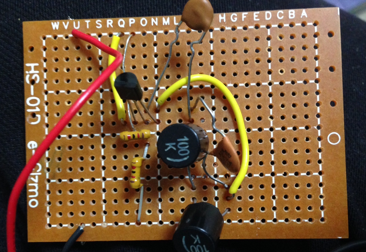
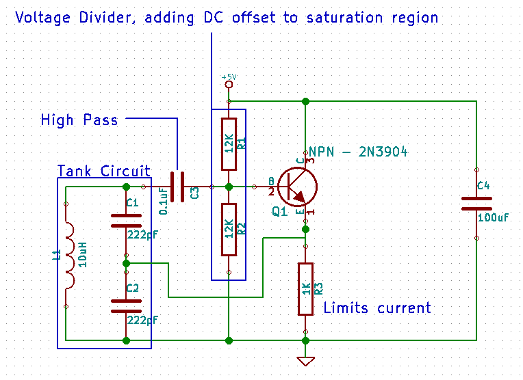
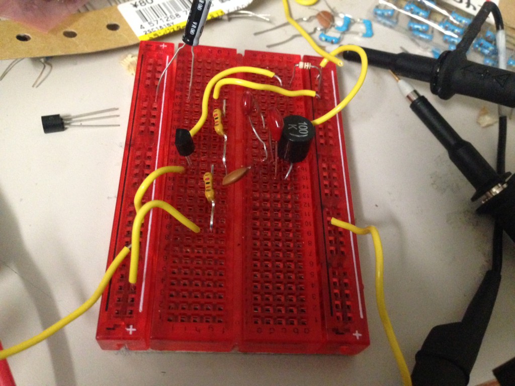
Today I built up the Hartley Oscillator shown above, I used the following design:
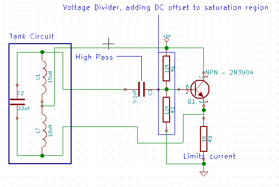
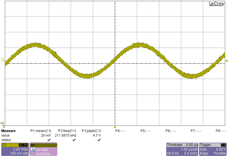
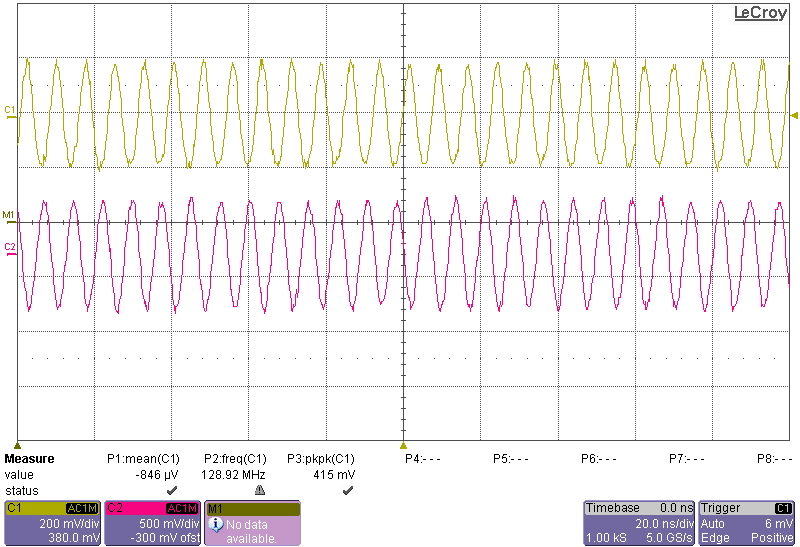
The Hartley Oscillator is the dual of the Colpitts. I’m still hazy on the details of the tank circuit. I’ll be reading up on this and will update this post accordingly. The circuit however oscillates well:
Category:
Uncategorized |
Comments Off on A Common Emitter Hartley Oscillator Notes
December 14, 2014, 5:03 pm

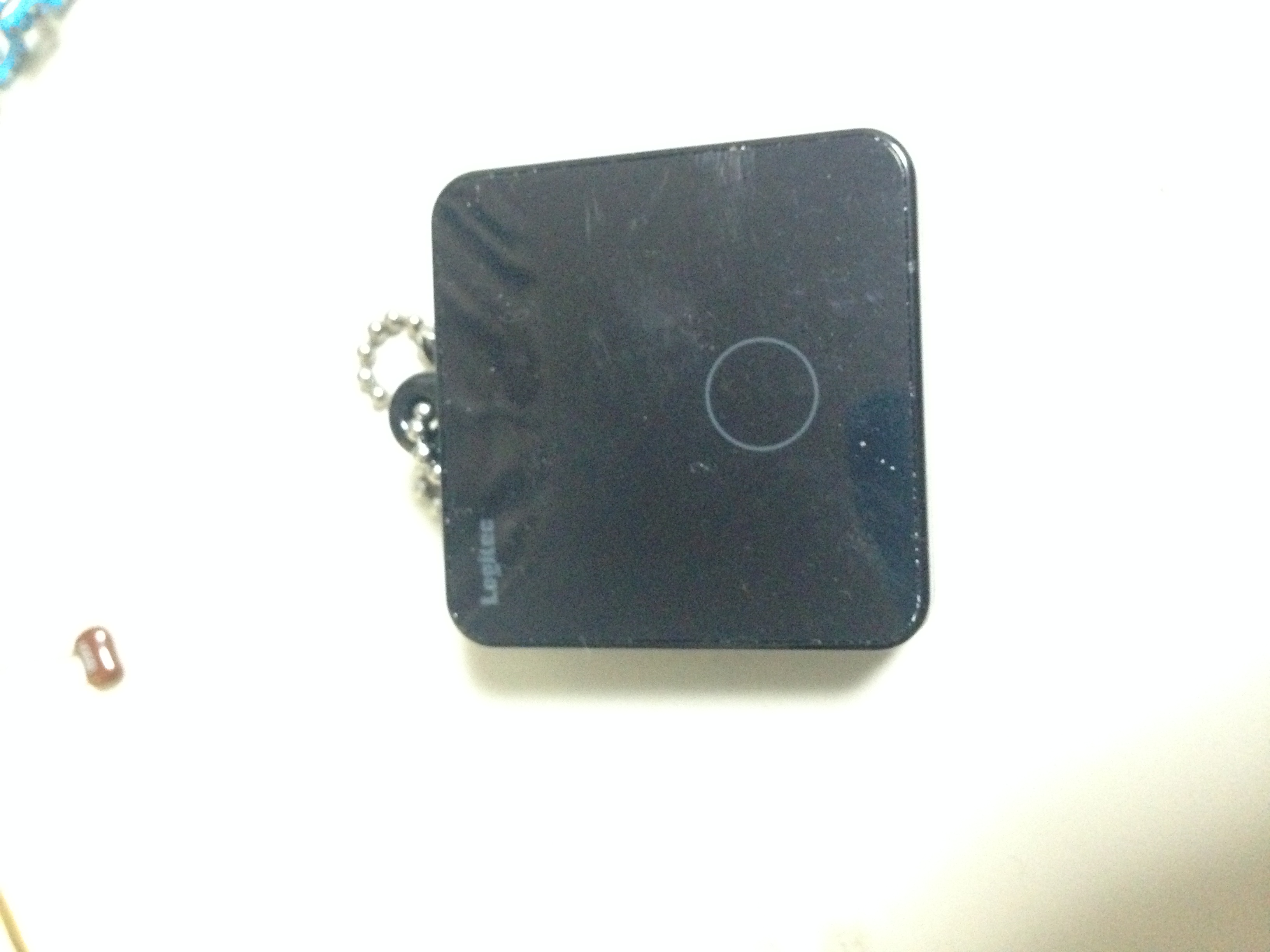
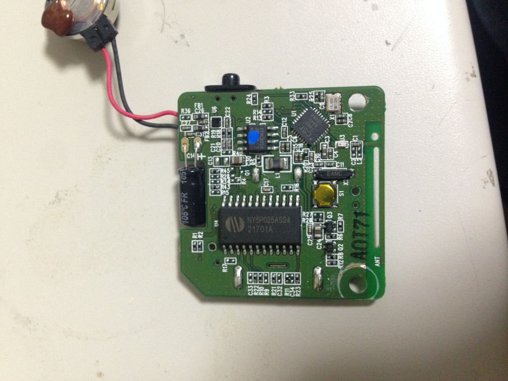
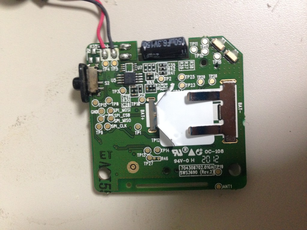
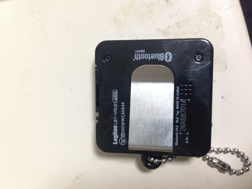
I picked this up in Akihabara yesterday. It was 100JPY (about 1USD). It appears to be a bluetooth LE dongle that makes your iPhone vibrate when you press the button. The Japanese documentation is here. I guess the idea is you use it to find your phone when you’ve lost it… wonder what you do when you lose it though…
It looks like it might be reasonably hackable, you can see from the pics below it’s using SPI parts, and the SPI signals have been broken out on to pads which is nice.
The main components seem to be:
NY5P025AS24: A cheap 4bit? CPU
CSR-1000A04U152AZ: The bluetooth LE part
ATMLH216: A small EEPROM
Category:
Uncategorized |
Comments Off on Logitec LBT-VRU01 (bluetooth LE iPhone locator?)
December 14, 2014, 1:31 am
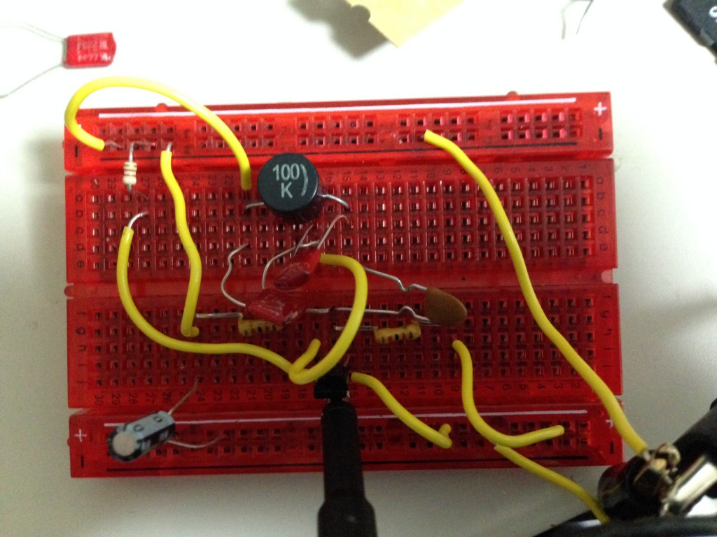
Today I built up a colpitts oscillator (shown above). The Colpitts oscillator is a tank (or LC network oscillator). It uses the resonance of an LC network which I looked at yesterday in a feedback loop to generate a oscillation.
The circuit I used is shown above, I’ve annotated the function of the different parts of the circuit as I understand it.
I’ve a lot more to learn to understand how this is working properly, but this is my vague understanding so far…
In terms of conventional current flow, when the circuit powers up, C1 and C2 are charged with a positive voltage at the point where they are connected to the emitter. As they charge, C1 pulls the base negative, reducing the current flow. The inductor also gets current pulled through it, inducing a magnetic field as it does so. The transistor will reduce the flow of current on out of the emitter as the current on the base decreases. Meaning C1 and C2 will being to discharge. As they do so, current will no longer flow through the inductor. The magnetic field will therefore collapse, the breakdown of the field again generates a current, but this time in the opposite direction. It charges C1 and therefore C2, resulting in a resonance. This resonance is maintained my the positive feedback from the transistor.
Here are some waveforms I recorded:
[UPDATE]
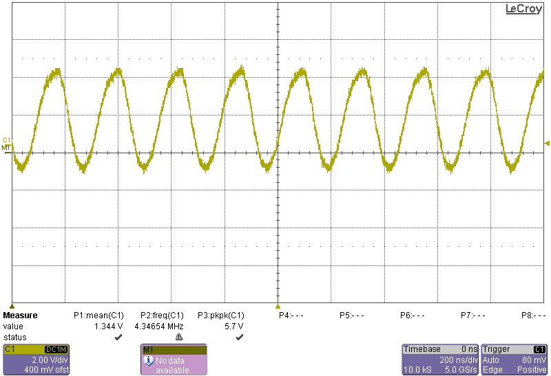
After reviewing the circuit, I realized 2 things. 1) It should have been oscillating at 4MHz. 2) I’d omitted the feedback from the emitter to the tank!
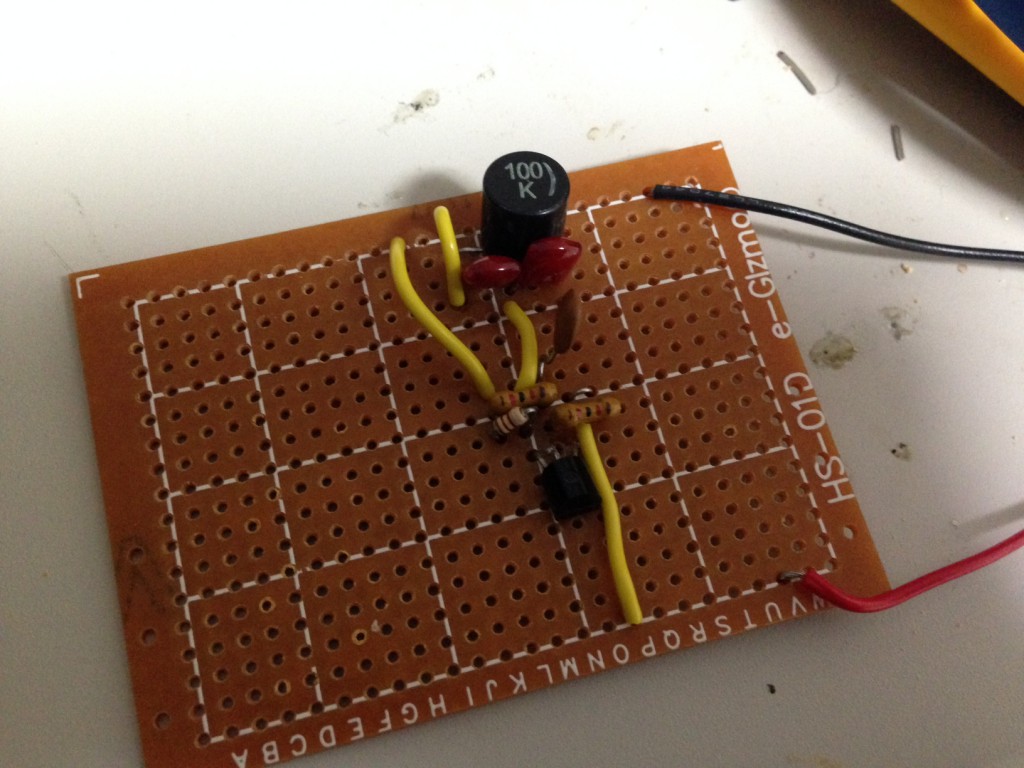
After fixing this the circuit correctly oscillated at 4MHz, I also no longer needed the decoupling capacitor! Here’s the new output waveform:
Category:
Uncategorized |
Comments Off on NPN Common Collector, Colpitts oscillator notes