December 18, 2014, 5:55 am
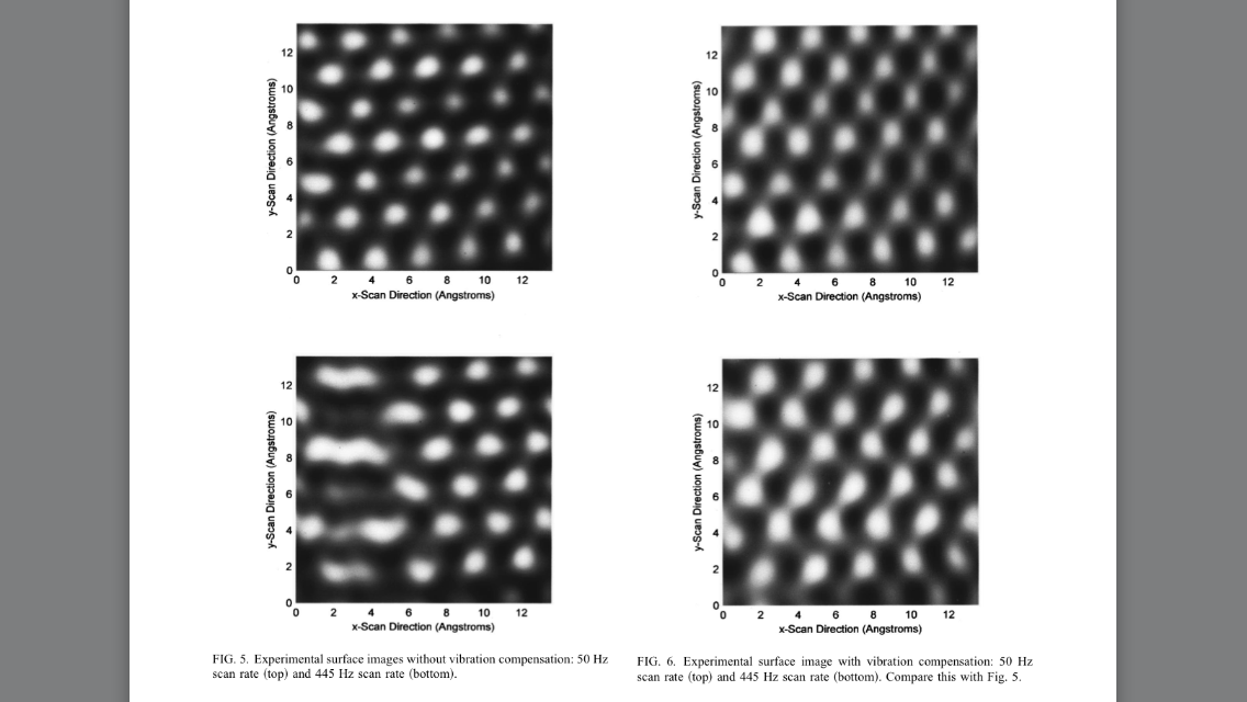
I’ve a long standing interest in STM projects since seeing the various low cost and amateur project attempts many years ago. I recently came across this paper describing a method for compensating for the probe vibration. The results (shown on HOGP below) see quite impressive. And allow for a scan rate of a few hundred Hertz.
Vibration compensation for high speed scanning tunneling microscopy
D. Croft and S. Devasia,
Rev. Sci. Instrum. 70, 4600 (1999)
Category:
Uncategorized |
Comments Off on STM vibrational compensation
December 17, 2014, 11:31 pm

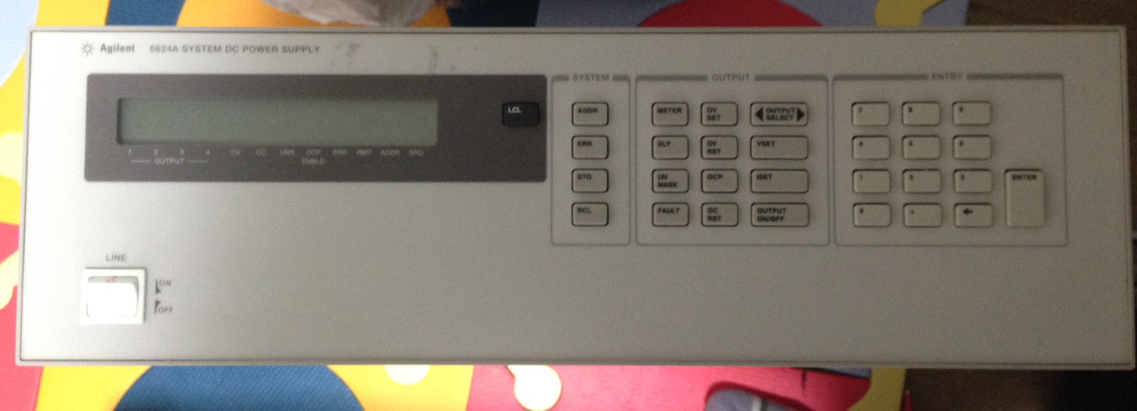
I picked up a 6624A power supply the other day, it was going for about 20USD so I couldn’t resist it. The thing is a beast, 4 channels, 2 going to 50V, and 2 going to 20V. It can source 5A at 7V, 2A at 20V and 0.8A at 50V. And the thing is HUGE. I have to admit to being slightly scared of this thing (probably wise given how much voltage/current it can source).
Being a “system” power supply, it has no banana plugs on the front. I opened it up to see if I could add any. It does look like there’s space, but it certainly wasn’t designed for them to be fitted as an option. I’ll need to cut through the front metal shielding.
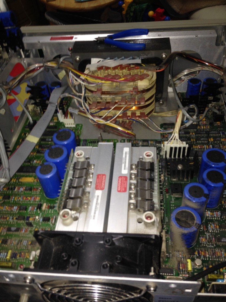
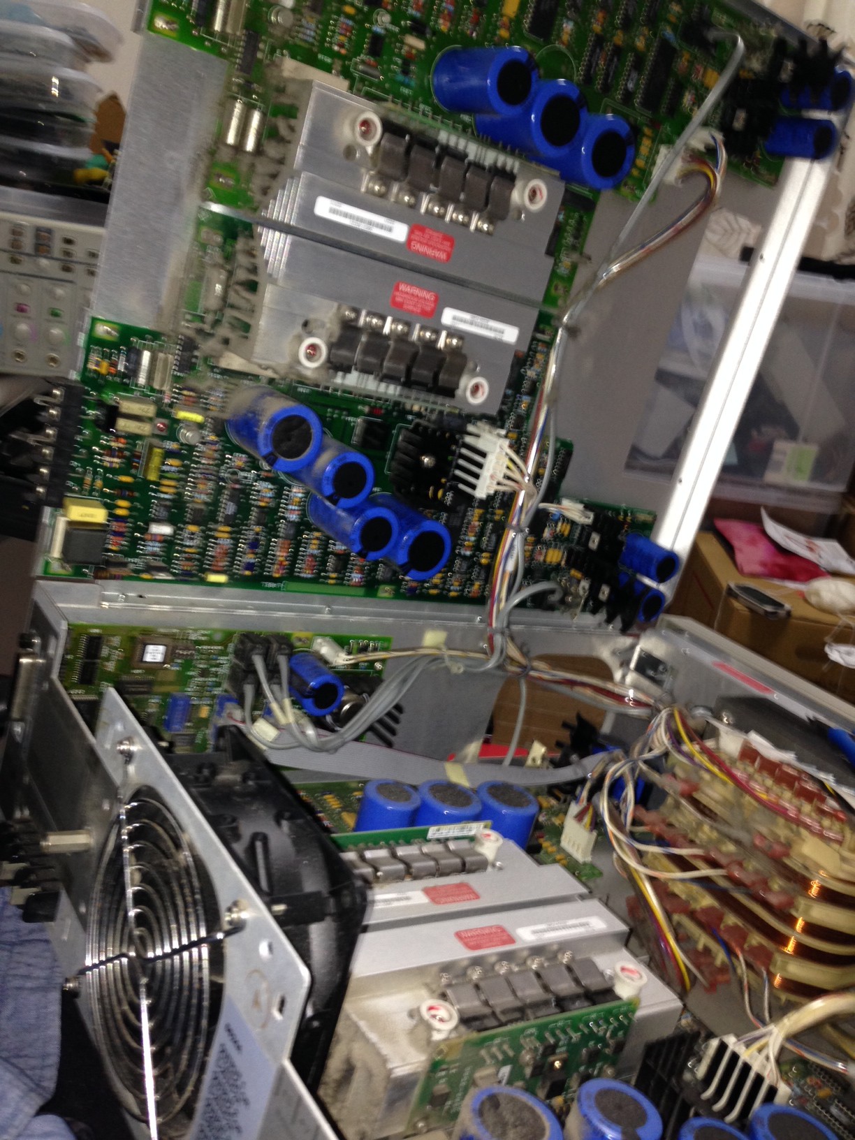
For some reason I’m reminded of pulling apart washing machines as a kid. This transformer is massive! I know why it’s so heavy now.
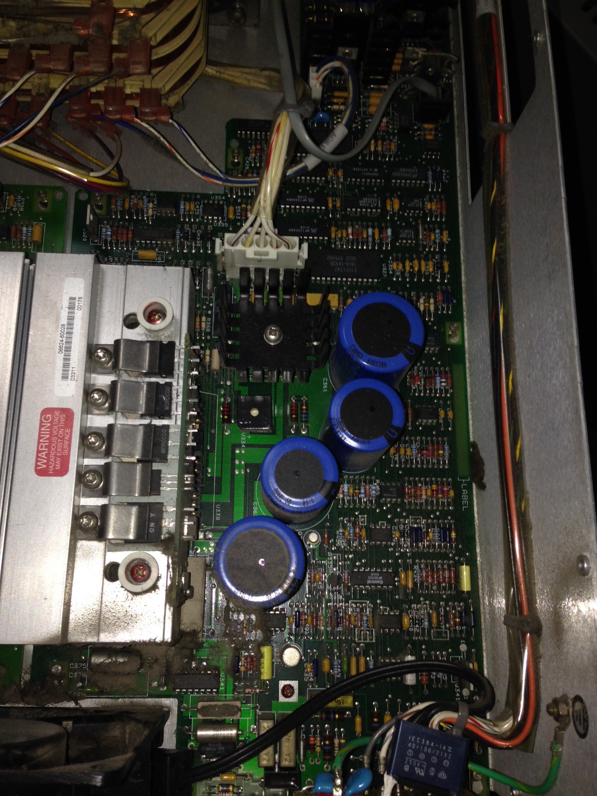
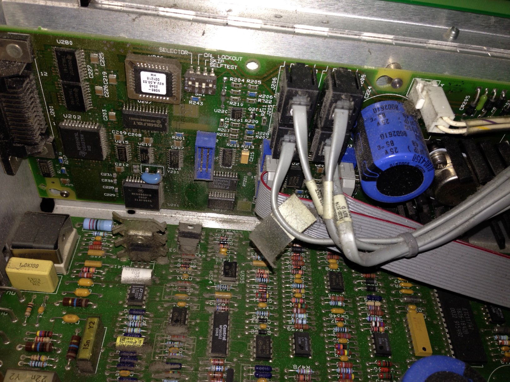
A few other pics. You can see that the channel modules are entirely separate the design varies significantly between the 20 and 50V channels.

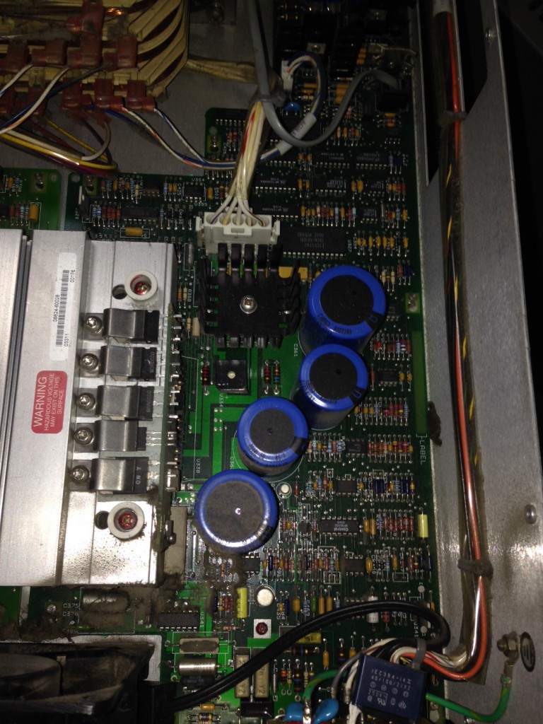

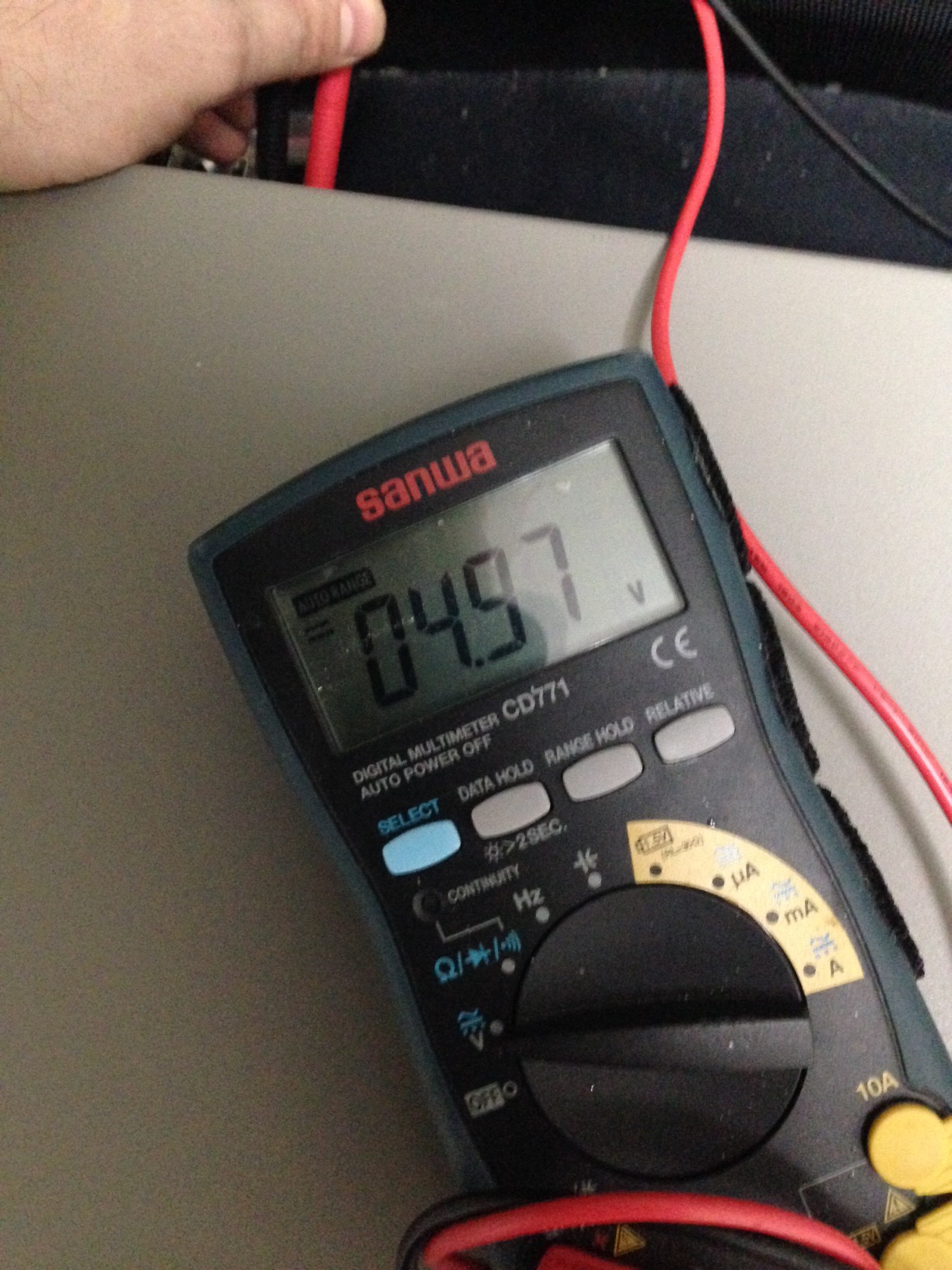
I briefly checked the first channel, (set at 5V). Not too bad for 20USD:

Category:
Uncategorized |
Comments Off on Agilent 6624A DC System Power supply
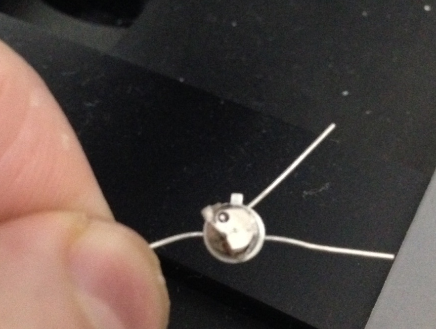
December 16, 2014, 10:51 pm
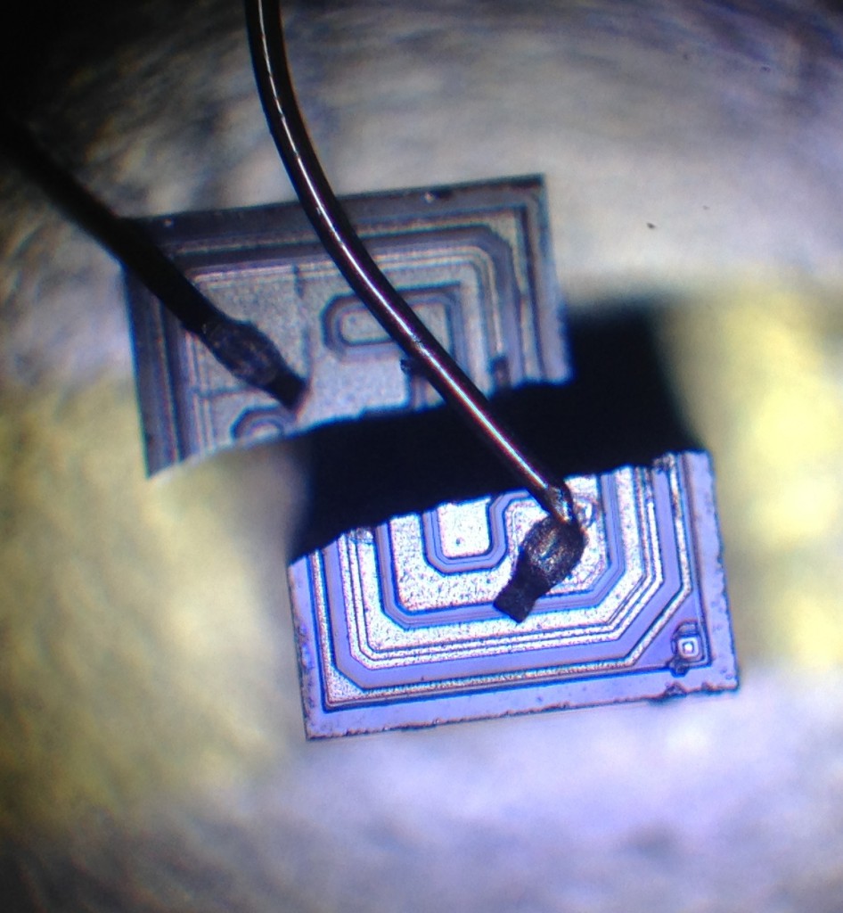
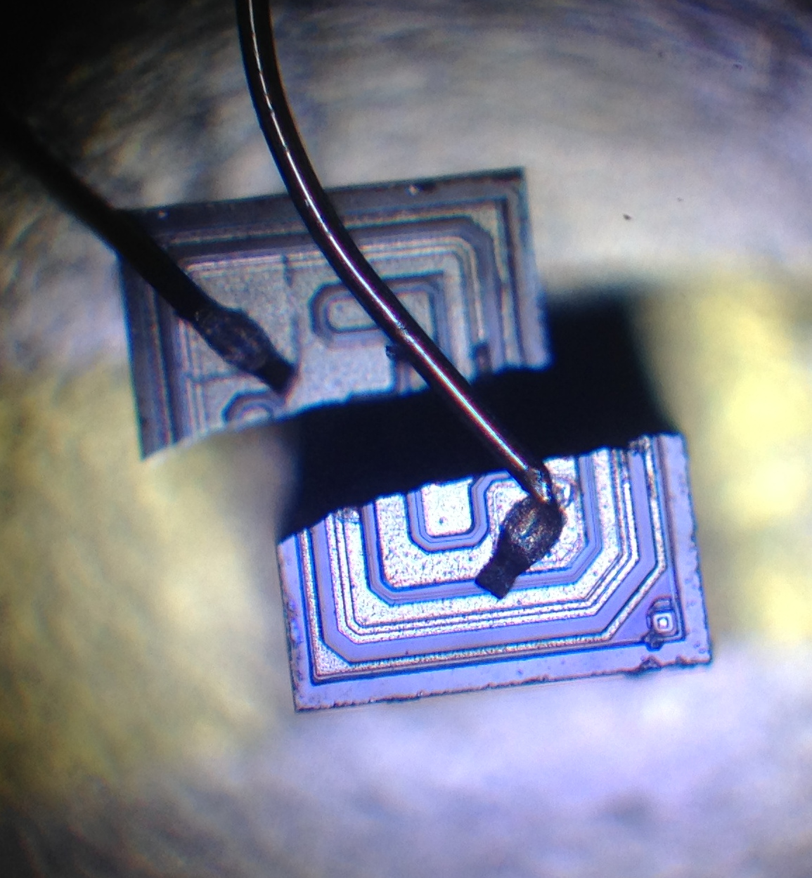
I was curious to know what a transistor die looked like so I hacked the can off a 2N2222 and up it under my recently acquired microscope. The die image is above, I’m not sure if I cracked it opening the can or blew it up (it was suspect anyway). Interesting to note that it only has 2 wirebonds. I assume this means that the base is connected directly to the substrate which is P type material?
December 16, 2014, 12:58 am
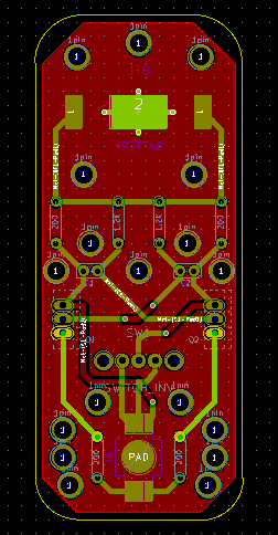
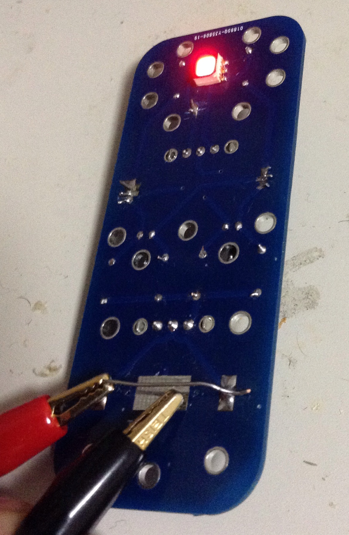
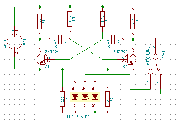
Based on the Astable multivibrator circuit I built the order day I put together the PCB design shown above. The design is also on githib here. Tomorrow I’ll print it out and make sure everything looks right then send it out for fabrication. Schematic below for reference:
UPDATE:
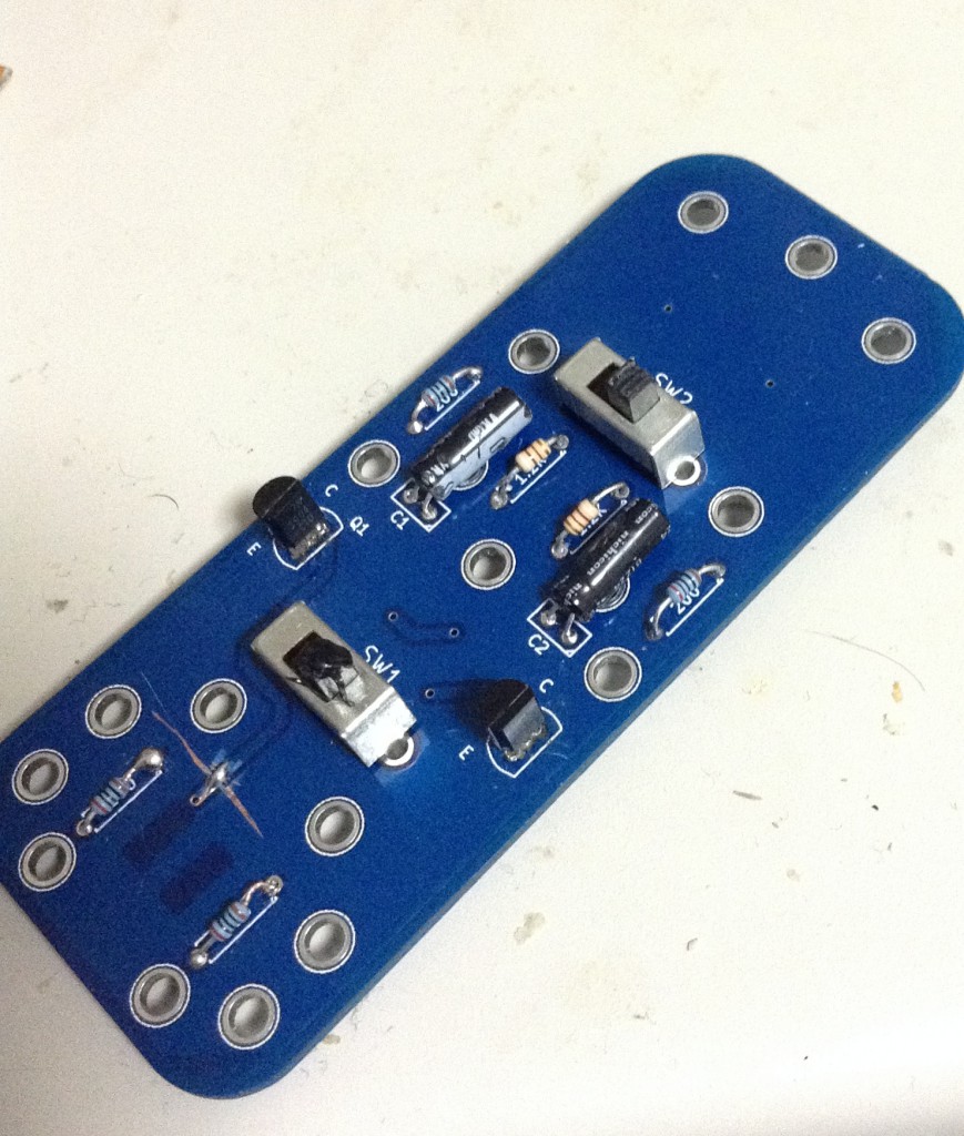
I got the PCB fabricated and built it up, it works well. Pictures below, bodges on the board are entirely myself during the build process, they layout is fine. If I fab them again I’ll probably stick the RGB LED on the component side!

Category:
Uncategorized |
Comments Off on Astable multivibrator RGB flasher PCB design