BMP180 Barometric Pressure Sensor

BMP180

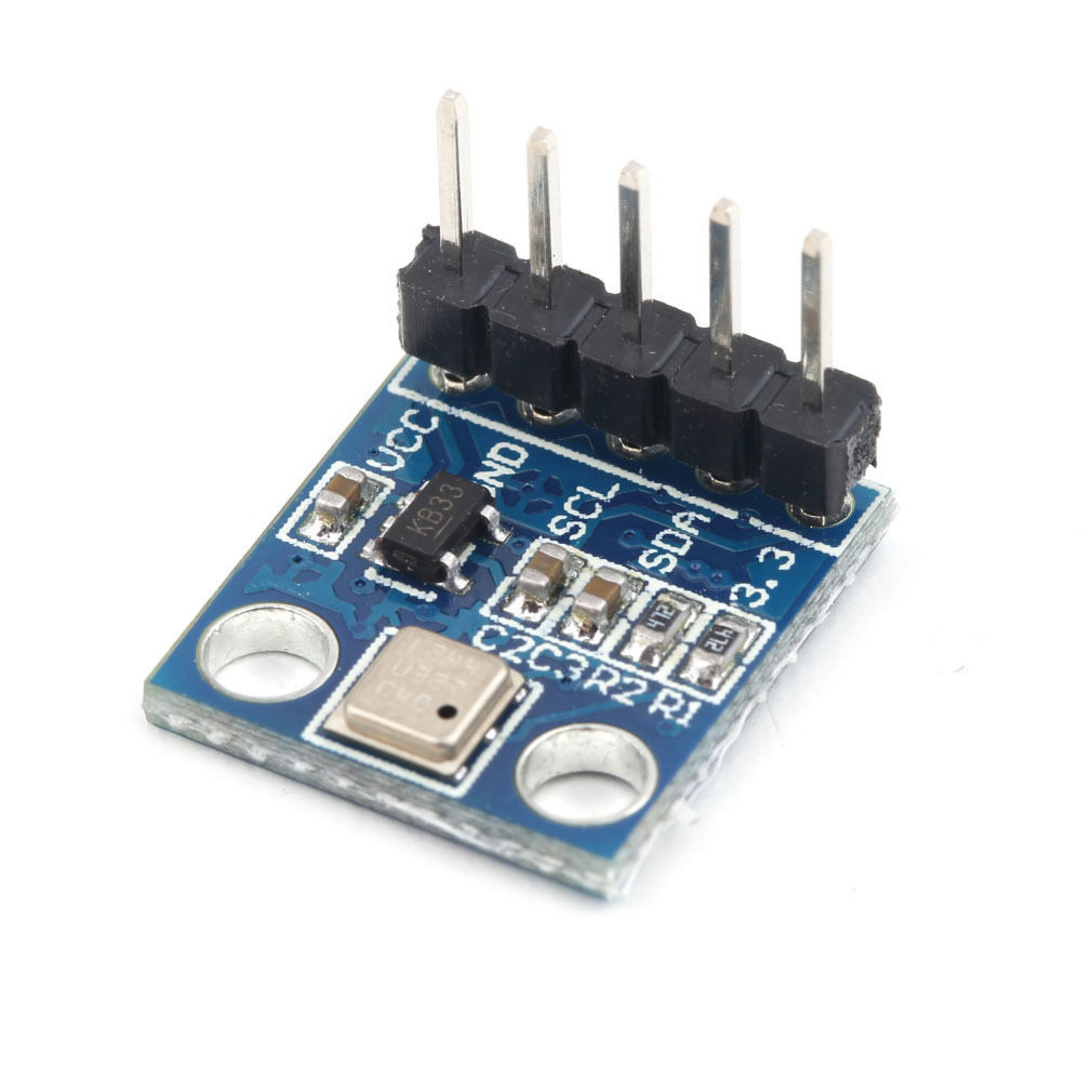
I pick the module above up on ebay for about 2USD shipped. I figured at that price it would be interesting to pay around with. As a first step I attached it to a bus pirate v4 to see if I could get some basic readings, this post contains my notes on reading the temperature from the device. It should be pretty easy to modify this for pressure readings. The bus pirate setup looked like this, pretty standard I2C connection:

busp_bmp180

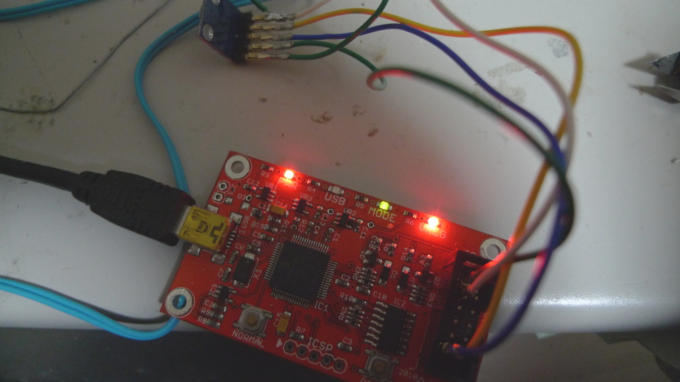
For these tests the initial, I2C setup was as described here. Both the 3.3V and VCC lines on the module needed to be connected to the 3.3V supply. The output of the bus scan was as follows:

I2C>(1)
Searching I2C address space. Found devices at:
0xEE(0x77 W) 0xEF(0x77 R)

The address values above are correct according to the datasheet. After the initial scan I shorted the power and ground lines (clever me!) and the magic smoke was released from VR2. Looks like I’ll be replacing that. However, surprisingly everything still works.

Before you can do much with the BMP180 you need to read the calibration values from its EEPROM. These start at EEPROM address 0xAA and are described on page 15 of the datasheet. Here’s an example of how you’d read the first calibration value, which is stored at indexes 0xAA and 0xAB with the bus pirate. Writing 0xAA to 0xEE selects the register. Reading from 0xEF then reads the register bytes. It looks like it auto-increments too:

I2C>[0xee 0xaa]
I2C START BIT
WRITE: 0xEE ACK
WRITE: 0xAA ACK
I2C STOP BIT
I2C>[0xef rr]
I2C START BIT
WRITE: 0xEF ACK
READ: 0x1F
READ:  ACK 0x98
NACK
I2C STOP BIT

Here are the register values I read on my device, with the values required for temperature conversion decoded as decimal.

NAME: REG IDX  : VALUES    : DEC
AC1 : 0xAA 0xAB: 0x1F 0x98 : 8088
AC2 : 0xAC 0xAD: 0xFB 0x9E : -31646
AC3 : 0xAE 0xAF: 0xC7 0x17 : -18199
AC4 : 0xB0 0xB1: 0x81 0x51 :
AC5 : 0xB2 0XB3: 0x62 0x3A : 25146
AC6 : 0xB4 0xB5: 0x3B 0xB2 : 15282
B1  : 0xB6 0xB7: 0x19 0x73 :
B2  : 0xB8 0xB9: 0x00 0x2A :
MB  : 0xBA 0xBB: 0x80 0x00 :
MC  : 0xBC 0xBD: 0xD1 0xF6 : -20982
MD  : 0xBE 0xBF: 0x0A 0xAB : 2731

As I understand it writing 0x2e to register 0xf4 selects temperature reading:

I2C>[0xee 0xf4 0x2e]
I2C START BIT
WRITE: 0xEE ACK
WRITE: 0xF4 ACK
WRITE: 0x2E ACK
I2C STOP BIT

The temp can then be read by writing 0xf6 to select the MSB (and 0xf7 for LSB), and then reading from register 0xef:

I2C>[0xee 0xf6]
I2C START BIT
WRITE: 0xEE ACK
WRITE: 0xF6 ACK
I2C STOP BIT
I2C>[0xef r]
I2C START BIT
WRITE: 0xEF ACK
READ: 0x59
NACK
I2C STOP BIT

I2C>[0xee 0xf7]
I2C START BIT
WRITE: 0xEE ACK
WRITE: 0xF7 ACK
I2C STOP BIT
I2C>[0xef r]
I2C START BIT
WRITE: 0xEF ACK
READ: 0xC3
NACK
I2C STOP BIT

The above reads show a value of 0x59 for the MSB and 0xC3 for the LSB. Converting these to a single decimal gives 22979. Page 15 of the datasheet describes how to convert the temperature and the calibration values into a reading in Celsius. I threw this all into bc:

x=(22979-15282)*(25146/(2^15))
y=(-20982*(2^11))/(x+2731)
z=x+y
((z+8)/(2^4))/10
5.873557310957312033718

So approximately 6 degrees. Given it’s about 4 degrees outside in Tokyo, and I don’t have the heating on that seems about right!

If I decide to move forward with this part I’ll likely attach it to a dedicated microcontroller now I have basic I2C comms working.

Creating an SVG in Javascript using FabricJS and downloading it locally

simplesvg

This following short example creates an canvas image using FabricJS. Pressing the draw, then save button creates an SVG representing this image, then creates a file based on this image using session local storage. Finally it adds a download link to this file to the html. The user can then download the SVG file to local storage. This has only been tested on Firefox.

UPDATE: FabricJS 1.4.0 appears to have issues where line coordinates get randomly offset. I’ve updated the example below to link to 1.4.13, however 1.4.0 is still linked as the latest CDN version on the FabricJS site. The example below will work with 1.4.0, but I don’t recommend using it.

<html>

<script src="http://cdnjs.cloudflare.com/ajax/libs/fabric.js/1.4.13/fabric.min.js"></script>
<script langauge="javascript">

  var m_canvas;

  function do_draw() {
    // create a wrapper around native canvas element (with id="c")
    m_canvas = new fabric.Canvas('c');

    // create a rectangle object
    var rect = new fabric.Rect({
      left: 100,
      top: 100,
      fill: 'red',
      width: 20,
      height: 20
    });

    // "add" rectangle onto canvas
    m_canvas.add(rect);
  }

  function do_save() {
    var filedata=m_canvas.toSVG(); // the SVG file is now in filedata

    var locfile = new Blob([filedata], {type: "image/svg+xml;charset=utf-8"});
    var locfilesrc = URL.createObjectURL(locfile);//mylocfile);

    var dwn = document.getElementById('dwn');
    dwn.innerHTML = "<a href=" + locfilesrc + " download='mysvg.svg'>Download</a>";
  }
</script>

<body>

<canvas id='c'></canvas>
<input type="button" id="drawBtn" value="draw" onclick="do_draw()"></input>

<input type="button" id="saveBtn" value="save" onclick="do_save()"></input>
<div id='dwn'></div>

</body>
</html>

Creating an SVG in Javascript, trivial example

I’m no JS coder, but for my reference below is a simple example showing how to create an SVG image in Javascript. The code below also shows how the SVG element itself might be created in JS.

UPDATE: If you’re looking at creating SVGs in Javascript, I recommend checking out FabricJS, I found it much easier to get what I wanted working.

<html>

<body>
<script language="javascript">

var svgNS = "http://www.w3.org/2000/svg";  

function do_draw() {

  // The following commands can be used to create an SVG programatically
  // var mySVG = document.createElementNS("http://www.w3.org/2000/svg", "svg");
  // mySVG.setAttribute("height",300);
  // mySVG.setAttribute("width" ,300);
  // document.body.appendChild(mySVG);
  
  var mySVG = document.getElementById('mySVG')

  var circles = document.createElementNS("http://www.w3.org/2000/svg", "circle");
  circles.setAttribute("cx",20);
  circles.setAttribute("cy",20);
  circles.setAttribute("r",20);
  mySVG.appendChild(circles);
}

</script>


<svg id="mySVG" style="width:300px; height:300px" xmlns="http://www.w3.org/2000/svg" xmlns:xlink="http://www.w3.org/1999/xlink"/>
<input type="button" id="drawBtn" value="draw" onclick="do_draw()"></input><br><br>
<div id='main'></div>

</body>

</html>

esp8266 esp1 device programmer gerbers

esp8266esp1prog

esp8266esp1prog2

I decided I wanted a fabricated board for my esp8266 programmer. I’d previous made a quick board with wire wrap. So I put this design above together in Kicad. You can find the gerbers below, or if you like one drop me an email. One word of warning, the silk on these boards is wrong (it’s on the wrong side!). So if you do decide to build this be careful sticking the connectors on. You can also find all the files on github.

Download the gerbers here: esp8266prog

UPDATE:

Assembled and tested, works well:
progboard

This is a continuation of my notes on the esp8266 microcontroller, you can find a complete list of my esp8266 posts here