January 24, 2015, 12:07 am
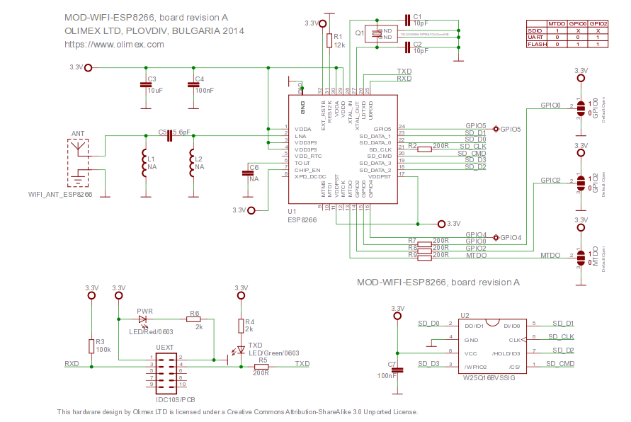
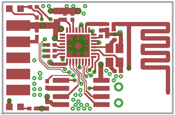
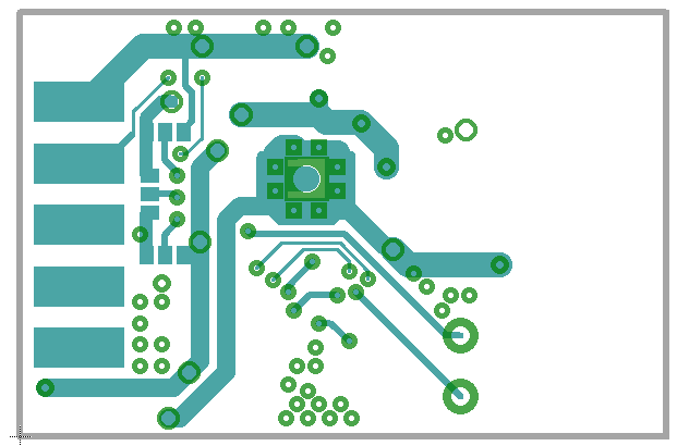
Olimex have made their esp8266 layout available here. It’s under a pretty permissive CC license (allowing commercial use with attribution). I’m interested in using this as a basis for my own designs. However Olumex use Eagle, and I’ve mostly using Kicad lately. This page contains image dumps of the schematic and layout for my reference in case I decide to use them as a basis for a Kicad design, I also generated the gerbers and attached them below.
Plug: I have a bunch of esp8266 related boards in my shop.
Gerbers using eagle (untested): espg.tar
The original Eagle file (also available on the Olimex site):
MOD-WIFI-ESP8266_eagle_sources
January 23, 2015, 8:45 pm
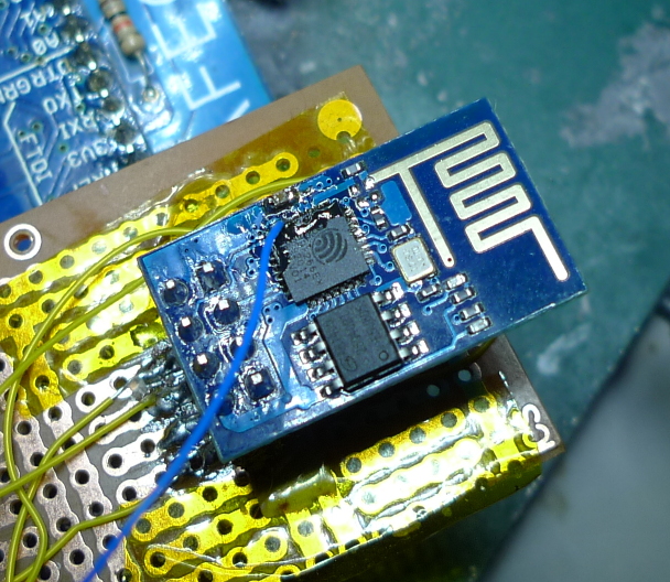
The esp8266 contains a 10bit ADC. There are apparently various issues, including instability when transmitting over Wifi, and the lack of a voltage reference. However it is usable. The analogue input is labeled “tout” on the pinout below:
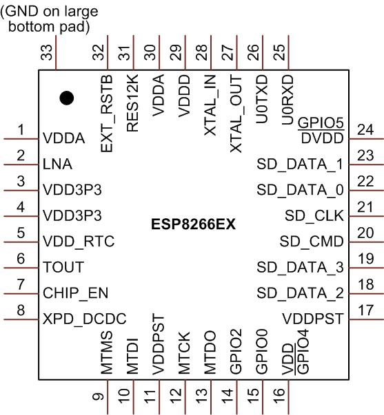
Unfortunately this isn’t broken out on the cheapest esp8266 boards (the esp1) but it’s possible to get access to it with some wirewrap wire and careful soldering (see image above).
The ADC input can then be read using some relatively simple C code as shown below. This code was adapted from an old version of the SDK (it doesn’t seem to be present in the current version).
I’ve also attached a complete working example that uses the function below: adc_test.tar
uint16 ICACHE_FLASH_ATTR adc_read(void) {
  uint8 i;
  uint16 sar_dout, tout, sardata[8];

  rom_i2c_writeReg_Mask(0x6C,2,0,5,5,1);

  // disable interrupts?
  SET_PERI_REG_MASK(0x60000D5C, 0x200000);
  while (GET_PERI_REG_BITS(0x60000D50, 26, 24) > 0); //wait r_state == 0
  sar_dout = 0;
  CLEAR_PERI_REG_MASK(0x60000D50, 0x02); //force_en=0
  SET_PERI_REG_MASK(0x60000D50, 0x02); //force_en=1

  os_delay_us(2);
  while (GET_PERI_REG_BITS(0x60000D50, 26, 24) > 0); //wait r_state == 0
  read_sar_dout(sardata);

  // Could this be averaging 8 readings? If anyone has any info please comment.
  for (i = 0; i < 8; i++) {
    sar_dout += sardata[i];
  }
  tout = (sar_dout + 8) >> 4; //tout is 10 bits fraction

  // I assume this code re-enables interrupts
  rom_i2c_writeReg_Mask(0x6C,2,0,5,5,1);
  while (GET_PERI_REG_BITS(0x60000D50, 26, 24) > 0); //wait r_state == 0
  CLEAR_PERI_REG_MASK(0x60000D5C, 0x200000);
  SET_PERI_REG_MASK(0x60000D60, 0x1); //force_en=1
  CLEAR_PERI_REG_MASK(0x60000D60, 0x1); //force_en=1
  return tout; //tout is 10 bits fraction
}
UPDATE: There’s also a system_adc_read function in the library symbols, I’ve not used it but it could be worth looking at.
This is a continuation of my notes on the esp8266 microcontroller, you can find a complete list of my esp8266 posts here
January 23, 2015, 2:45 pm
January 23, 2015, 12:26 am
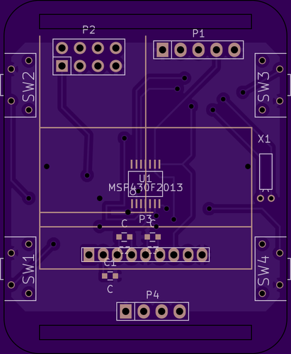
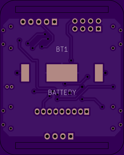
A long while ago, I played with an hacked together watch, based on the msp430. Recently I’ve been playing with a few interesting parts, the esp8266, an interesting I2C LCD and a cheap barometric sensor.
I decided to throw all these components together in a watch layout, just for fun! The PCBs are now out to fab and I’ll update this post when I’ve built everything up. I’m not sure I’ll actually place the esp8266 and if I do, for any kind of sensible power consumption it would need to be off most of the time.
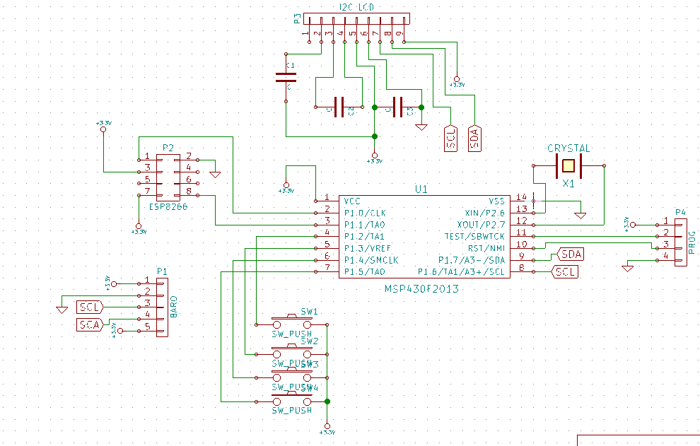
The schematic is below, and you can also find everything on github here.
Notes
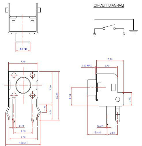
The switch used:
Other footprints are from the Kicad libraries.