January 25, 2015, 9:11 pm
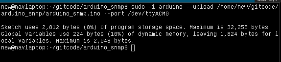
I’m not a huge fan of GUI tools, my workflow is mostly on the commandline. As such, I find the standard Arduino interface a bit painful, so I figured it was time to figure out how to get this working on the commandline. Historically, there have been a number of alternatively, the Arduino tools themselves are of course a wrapper round avrdude, so it’s possible to use that directly. There have also been other projects such as inotools, and sets of Makefiles which will work against Arduino ino files. However with version 1.5 of the Arduino tools command line support has been introduced natively.
Debian Jessie, unfortunately doesn’t appear to have 1.5 in it’s repository (it is after all still in beta). So you’ll need to download it. You can download the latest Beta here (1.5.8 at the time of writing).
First of all if you have the arduino package installed, you should probably remove it (apt-get remove arduino). You can then install the new arduino tools, for example (make sure you have a /opt directory):
tar zvxf arduino-1.5.8-linux64.tgz
sudo mv arduino-1.5.8 /opt/
sudo ln -s ./arduino-1.5.8 ./arduino
echo "PATH=\$PATH:/opt/arduino" >> ~/.bashrc
sudo sh -c 'echo "PATH=\$PATH:/opt/arduino" >> /root/.bashrc' # if you want it in the root path
You will need to restart your terminal to pickup the new arduino path. (note sudo arduino wont work, because sudo on Debian defaults to using “secure_path” for the path, you need to use sudo -i arduino). You can then upload a sketch from the commandline as follows:
sudo -i arduino --upload /home/new/gitcode/arduino_snmp/arduino_snmp.ino --port /dev/ttyACM0
You may, or may not need to use the full path, or specify the port/other configuration info. The tool is supposed to retain the port configuration set in the UI. A full list of command line options is available here.
January 24, 2015, 10:56 pm
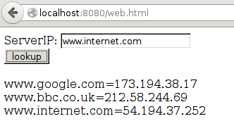
I wanted the ability to resolve DNS addresses in client side Javascript. Unfortunately you can’t do DNS lookups in browser. As a hack I wrote a quick DNS proxy in golang which allows the JS to perform GET requests to a golang server which will lookup and DNS entry and return IP addresses.
The HTML and golang code is below, there’s also a tarball here. You can run the go code with “go run”. If the html file is stored in the same directory you will be able to access it from localhost at http://localhost:8080/web.html.
<html>
<head>
<meta charset="UTF-8" />

<script>

  function gethostbyname(hostname) {
    var xmlHttp = new XMLHttpRequest();
    xmlHttp.open("GET", "http://localhost:8080/dns?hostname=" + hostname, false);
    xmlHttp.send(null);
    return xmlHttp.responseText;
  }

  function press() {
    var hostname = document.getElementById('hostname').value;
    document.getElementById('comms').innerHTML += hostname + "=" + gethostbyname(hostname)  + "<br>";
  }

</script>

</head>
<body>
  ServerIP: <input id="hostname" type="text" /><br>
  <input type="button" id="lookup" value="lookup" onclick="press()"></input><br><br>
  <div id='comms'></div>
</body>
</html>
package main

import (
    "net/http"
    "net"
    "fmt"
)

func DNSProxyHandler(w http.ResponseWriter, r *http.Request) {

  r.ParseForm()
  hostname := r.Form.Get("hostname")

  fmt.Printf("hostname: %s\n",hostname)

  addrs, err := net.LookupIP(hostname)

  var sendbytes string;
  if err == nil {
    sendbytes = addrs[0].String()
    fmt.Printf("sending: %s",sendbytes)
  } else {
    fmt.Printf("fail in dnsroxy\n")
  }

  fmt.Fprintf(w, "%s",sendbytes);

}

func main() {
  http.HandleFunc("/dns" , DNSProxyHandler)
  http.Handle("/", http.FileServer(http.Dir(".")))
  err := http.ListenAndServe(":8080", nil)
  if err != nil {
    panic("Error: " + err.Error())
  }
}
January 24, 2015, 12:50 pm
A new version of the SDK was released today. A few additional APIs have been introduced, but it appears that no existing functions have been changed/removed. I was able to replace the 0.9.3 SDK with this and compile my codebase successfully. I’ll update here after I’ve tried flashing a device. (UPDATE: I tested the ADC code from yesterday with the new SDK and it worked well)
There are a few interesting additions, there appears to be a new API called smartconfig, it looks like this allows the device to be configured from a smartphone. The protocols used are called AirKiss and ESP-TOUCH. I had a quick look through the library symbols, there wasn’t anything new that jumped out at me.
UPDATE: I’ve left what’s written below for reference, but the esp-open-sdk is a better solution, you can see my notes of that here.
As part of the process of installing the new version of the SDK, I’ve been tidying up my toolchain a bit. A complete tarball of my setup is here. This is the Linux setup. To download an install it you should be able to do the following:
sudo su
cd /opt
wget http://41j.com/blog/wp-content/uploads/2015/01/Espressif.0.9.5.tar.gz
tar xvzf Espressif.0.9.5.tar.gz
ln -s Espressif ./Espressif.0.9.5
cd Espressif
#install the Xtensa compiler
git clone -b lx106 git://github.com/jcmvbkbc/crosstool-NG.git
cd crosstool-NG
./bootstrap && ./configure --prefix=`pwd` && make && make install
./ct-ng xtensa-lx106-elf
./ct-ng build
PATH=$PWD/builds/xtensa-lx106-elf/bin:$PATH
However I’ve not yet tried the above, if you are interesting in giving it ago please let me know. But these notes are currently for my reference. Once the SDK is installed, I used the following Makefile for building my projects Makefile. Here’s an example project I’ve been working on which uses this Makefile: bGeigieNano_ESP8266.tar
This is a continuation of my notes on the esp8266 microcontroller, you can find a complete list of my esp8266 posts here
January 24, 2015, 12:07 am
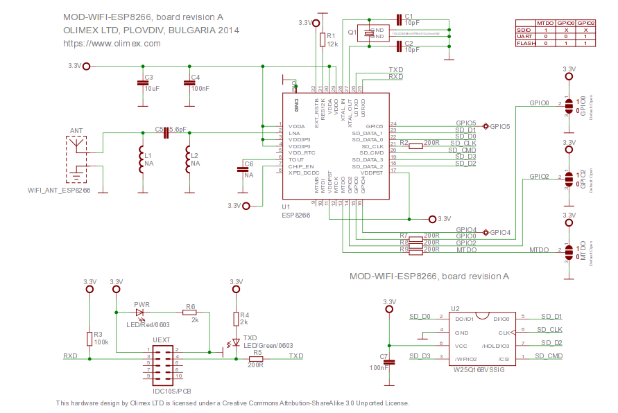
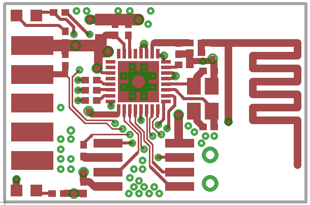
Olimex have made their esp8266 layout available here. It’s under a pretty permissive CC license (allowing commercial use with attribution). I’m interested in using this as a basis for my own designs. However Olumex use Eagle, and I’ve mostly using Kicad lately. This page contains image dumps of the schematic and layout for my reference in case I decide to use them as a basis for a Kicad design, I also generated the gerbers and attached them below.
Plug: I have a bunch of esp8266 related boards in my shop.
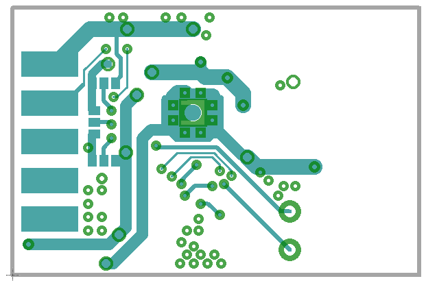
Gerbers using eagle (untested): espg.tar
The original Eagle file (also available on the Olimex site):
MOD-WIFI-ESP8266_eagle_sources
 RSS
RSS