Visit to see a SEM (electron microscope)
Today I went with some friends, my wife and 8 month old baby to see a SEM. We’re planning to buy one for shared use at a local hacker space (here in Japan).
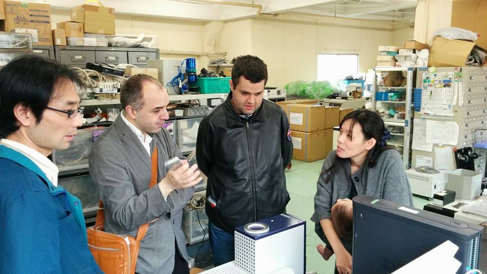
I’m the balding one, wearing a jacket and trying to look like I should be allowed to own an SEM.
The instrument bears little relation to the SEMs of old, or even the models from the 60s and 70s, it’s a ~2003 era instrument billed as a “deskside SEM”. Unfortunately, as far as I know, it’s only available in Japan. The device we looked at is similar to these current models.
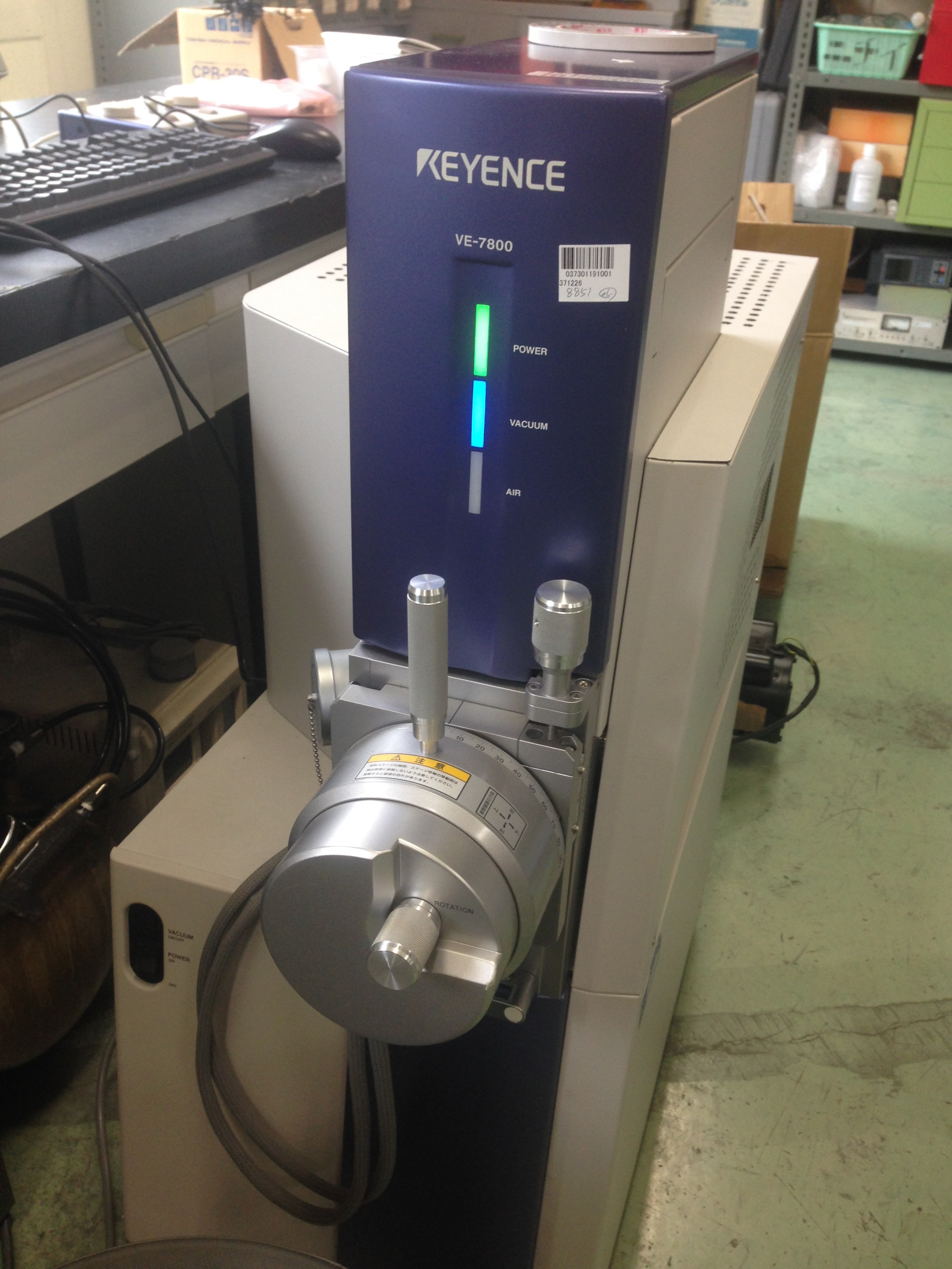

It’s also very quiet. SEMs operate at vacuum, and the unit uses as external roughing pump: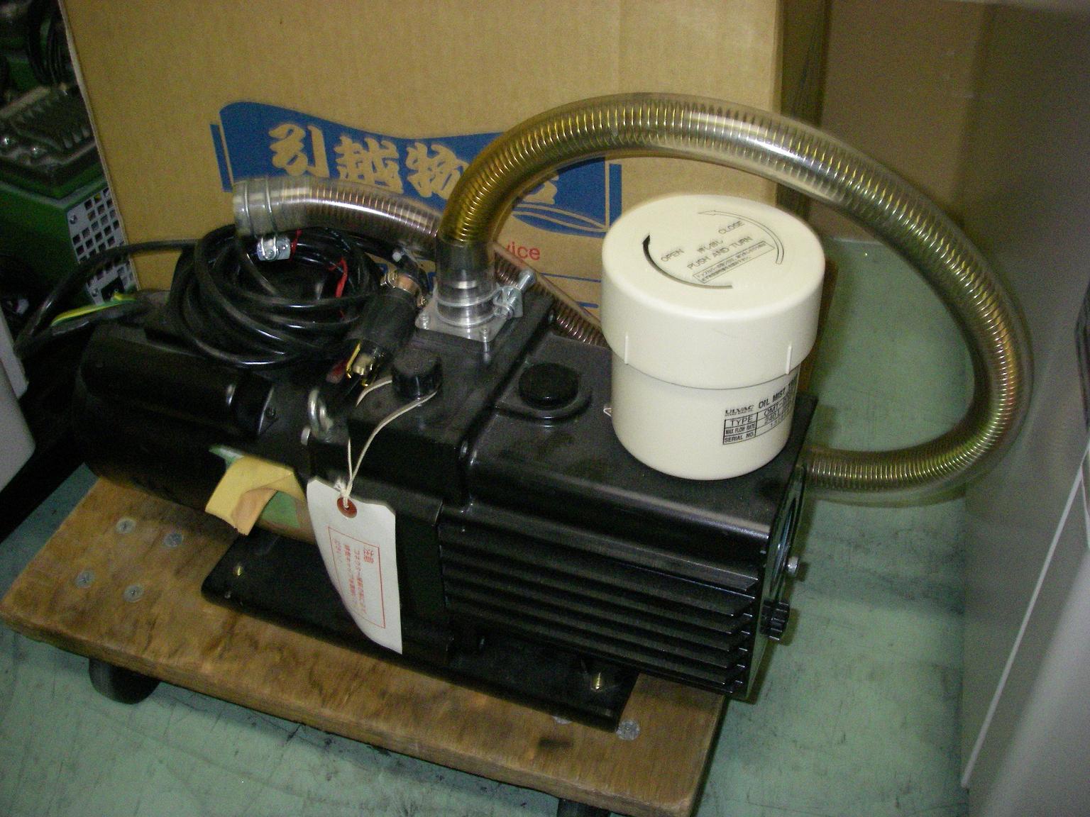
As well as an integrated turbo molecular while compressors and turbo molecular pumps have a reputation for being somewhat noisy the instrument was very quiet in operation. We could easy see this being operated in a residential environment if required.
It’s also very easy to run a sample on this machine, it takes about 5 minutes for the vacuum to come up before imaging. Here’s the sample chamber:
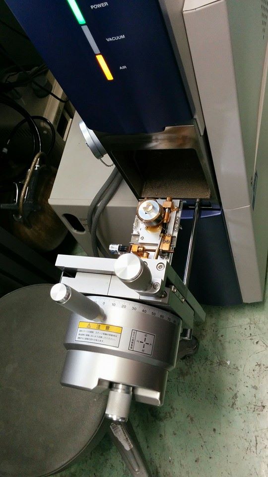
I was concerned that there might be special mounting requirements, but the sample just sits on some (I assume conductive) tape. It can also take what I believe is a standard sample mount, but this isn’t required.
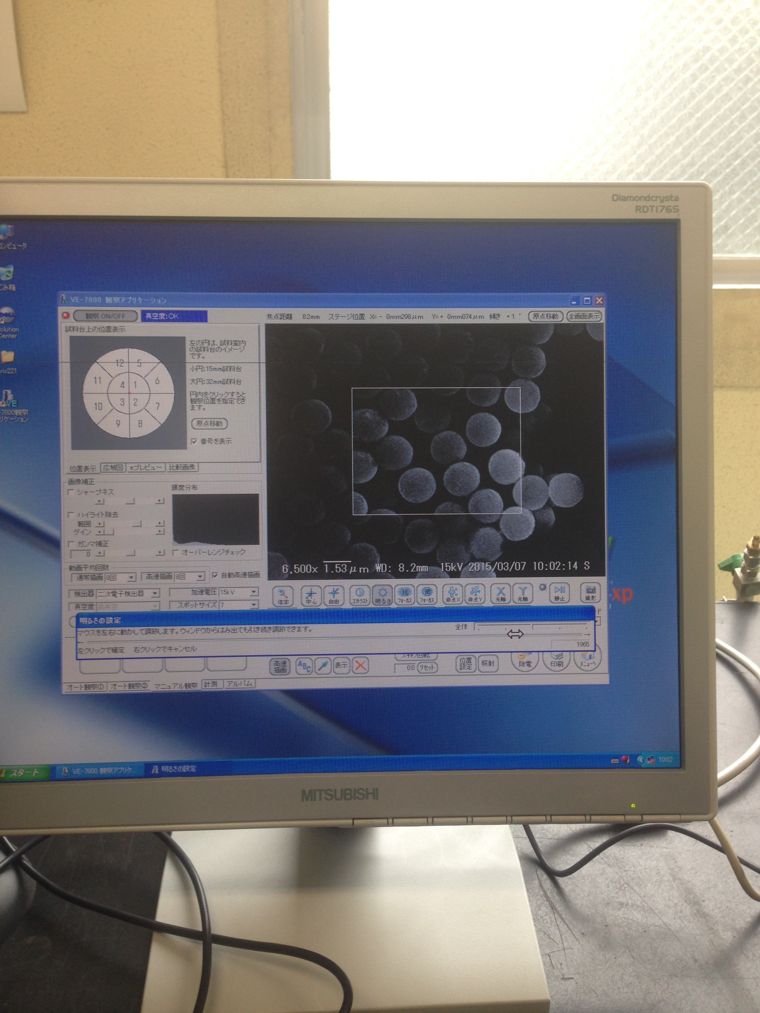
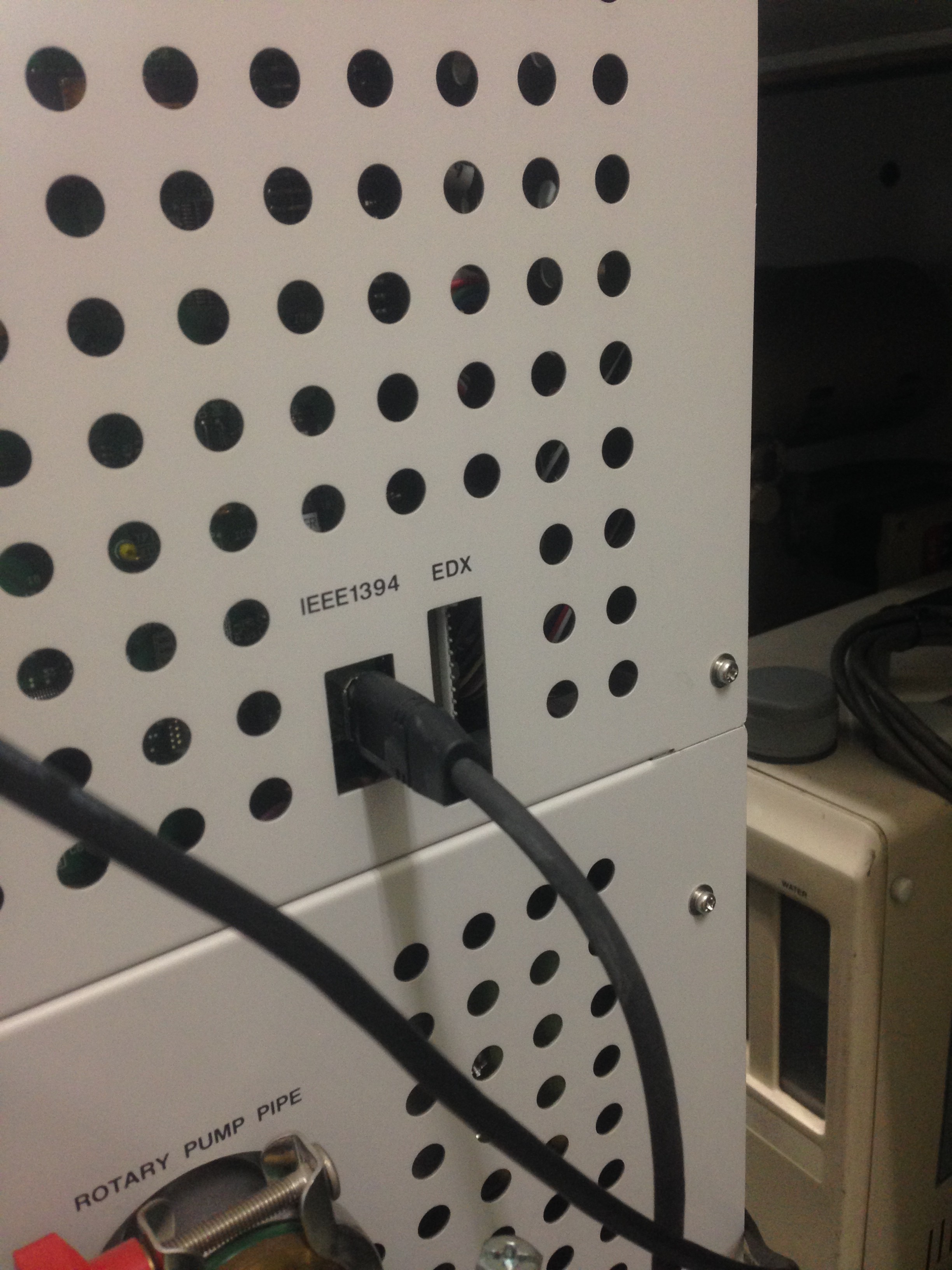 The instrument interfaces to the device PC over Firewire and USB. The software on the PC is locked to the instrument via a license file. After poking around the machine it was onto imaging. We started while a sample provided by the salesman. He said this was gold sputtered on a surface, I wasn’t aware that gold balled up like this when sputtered. I think something was possibly lost in translation (please leave a comment or email me if you have some background here). They however did appear to be uniform spheres of ~1micron in diameter:
Here we are at 35000x:
 The instrument is vibration sensitive, and you can see some noise at this point (there was nearby construction going on which might have affected things). This vibrational noise was only present on this image, it went away pretty quickly, but we’ll be keeping this in mind when we setup the instrument.
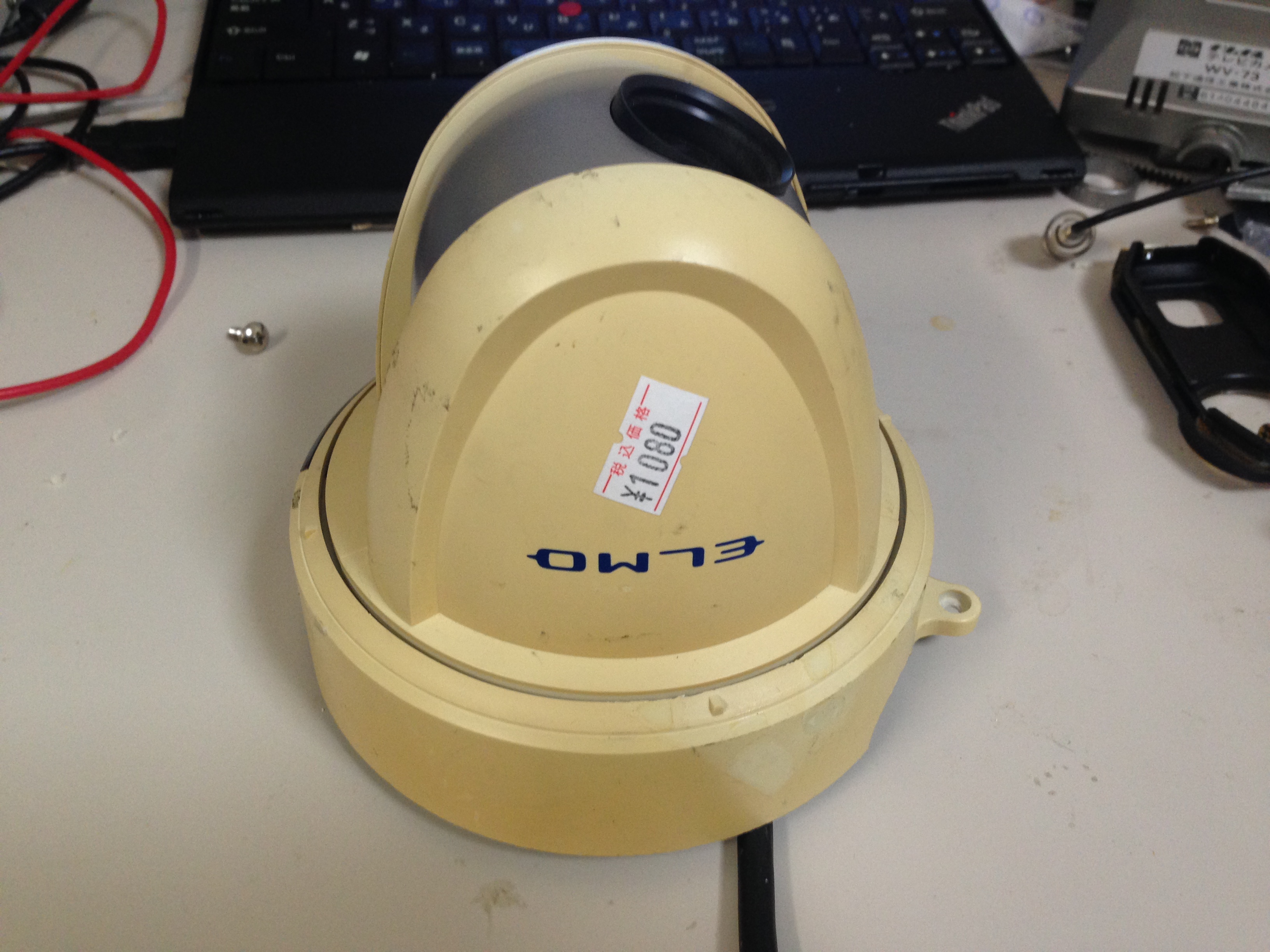
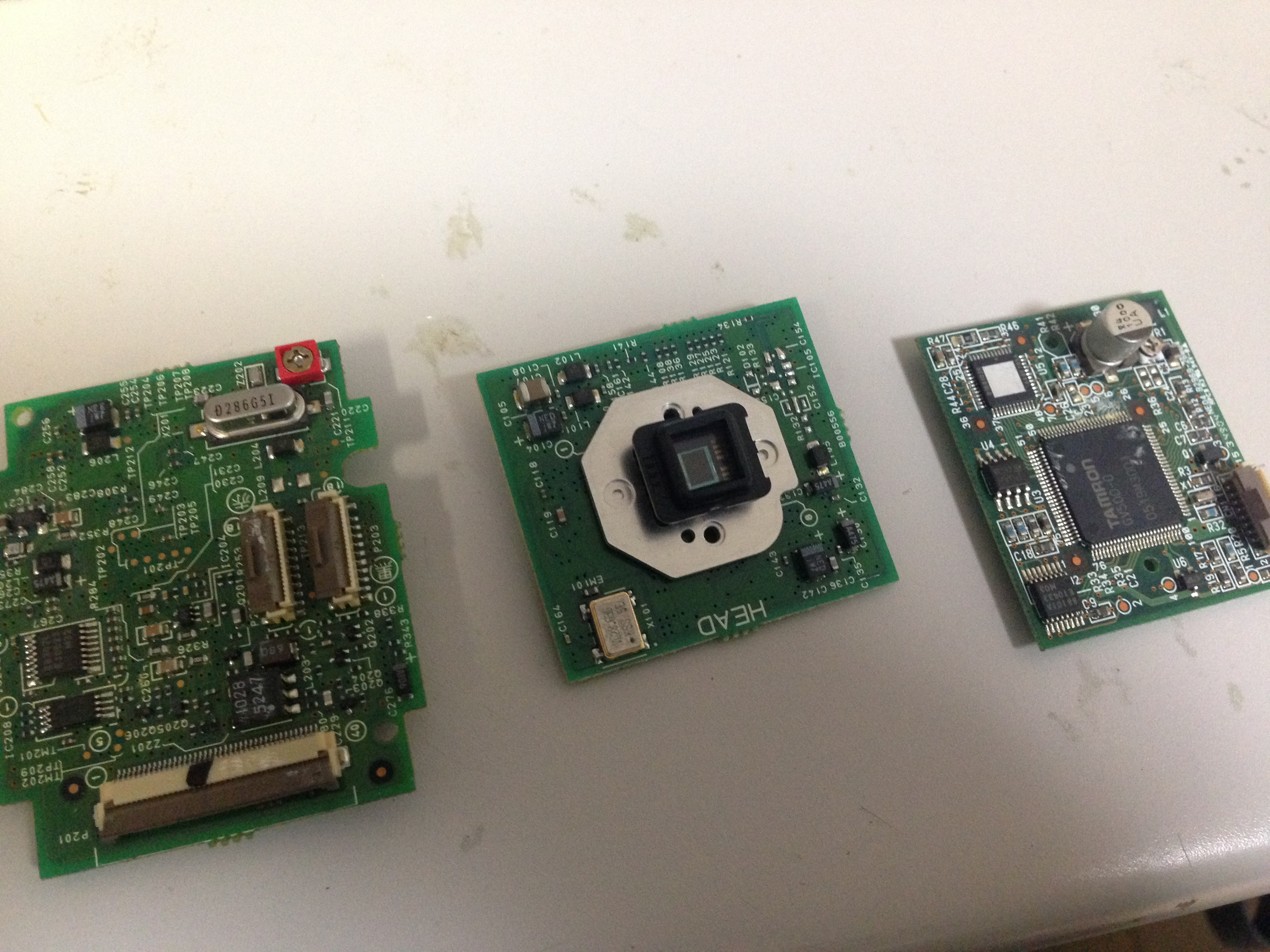
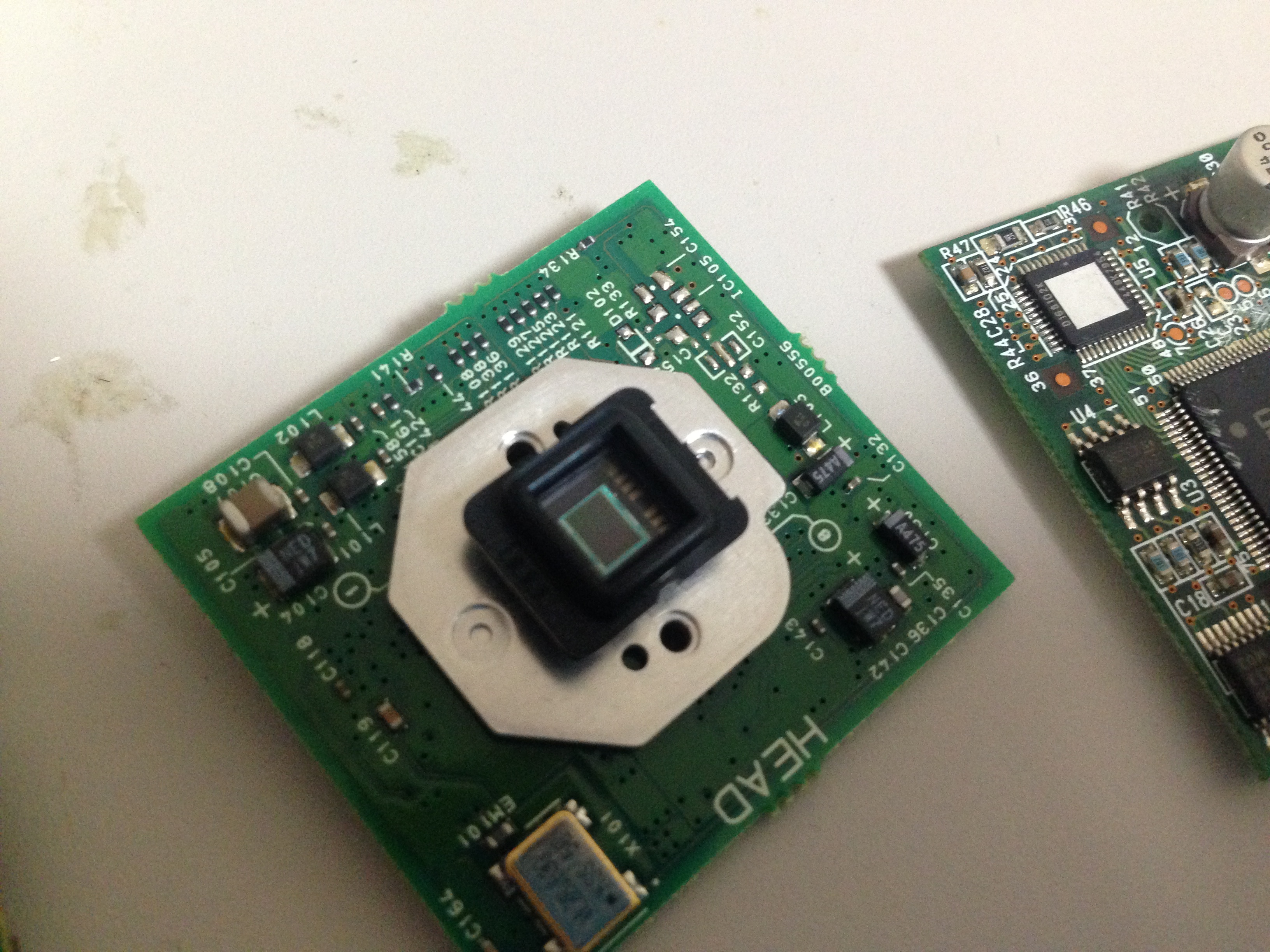
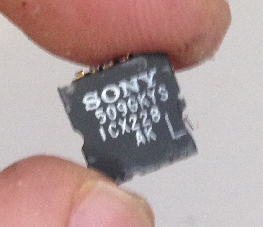
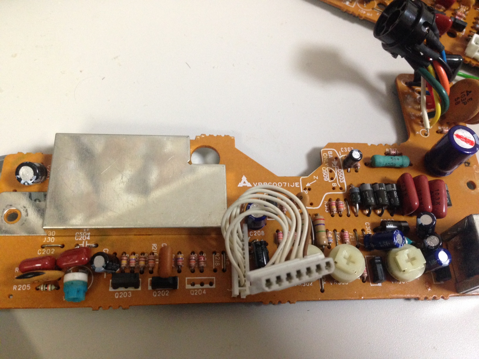
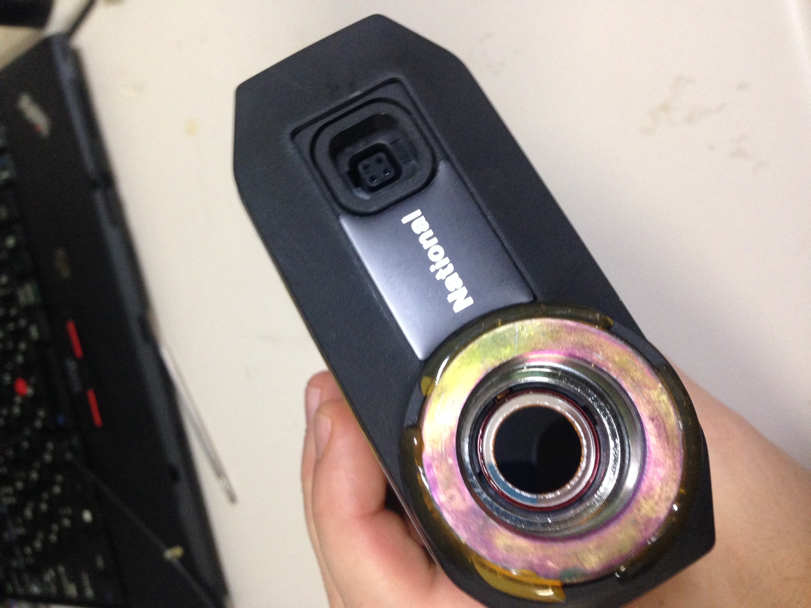
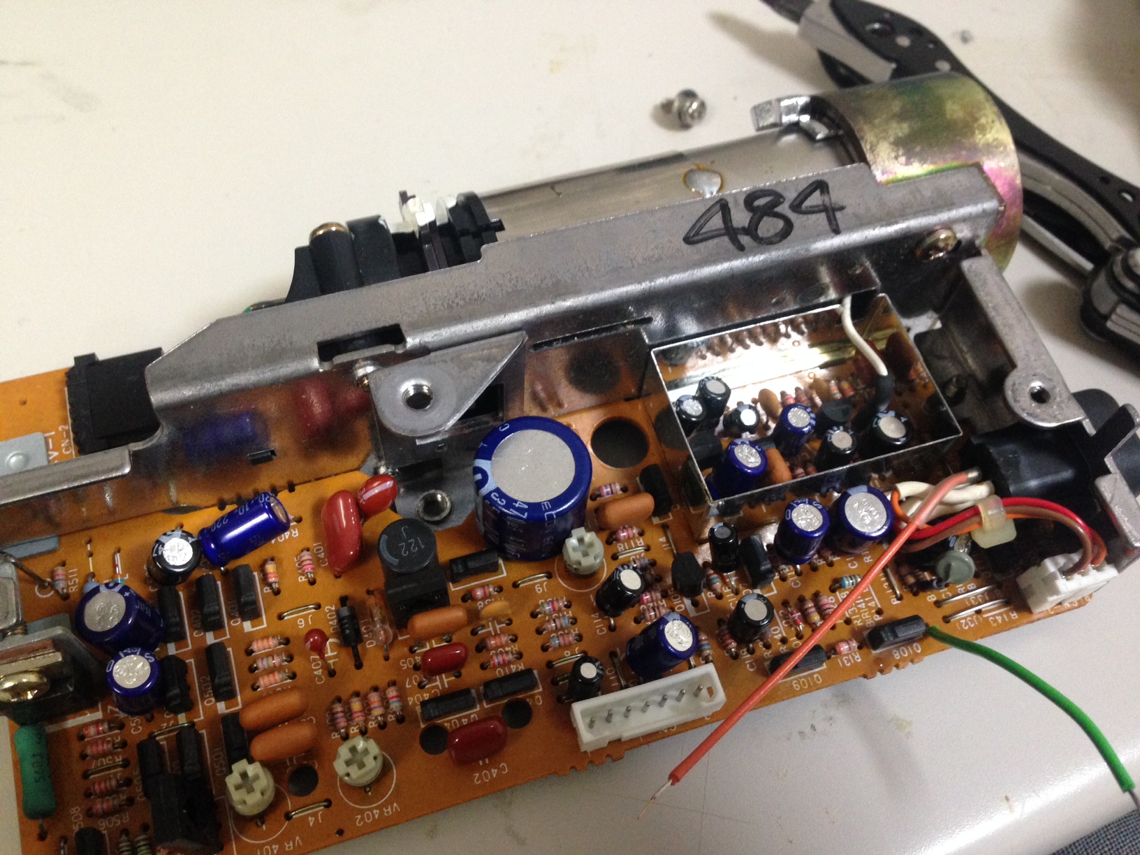
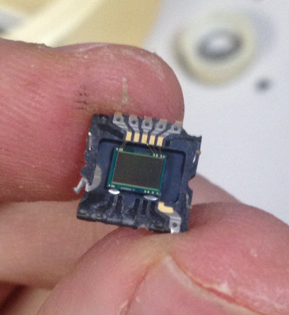
Now we’d confirmed that the machine was working we moved onto other samples, starting with the CCD IC I extracted yesterday. Here’s the chip again:
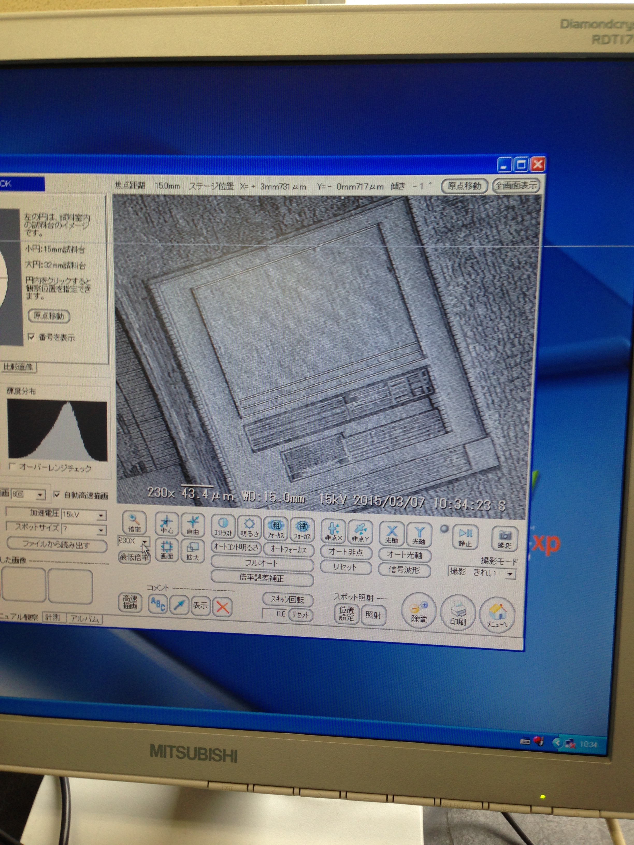
Under the SEM at x200:
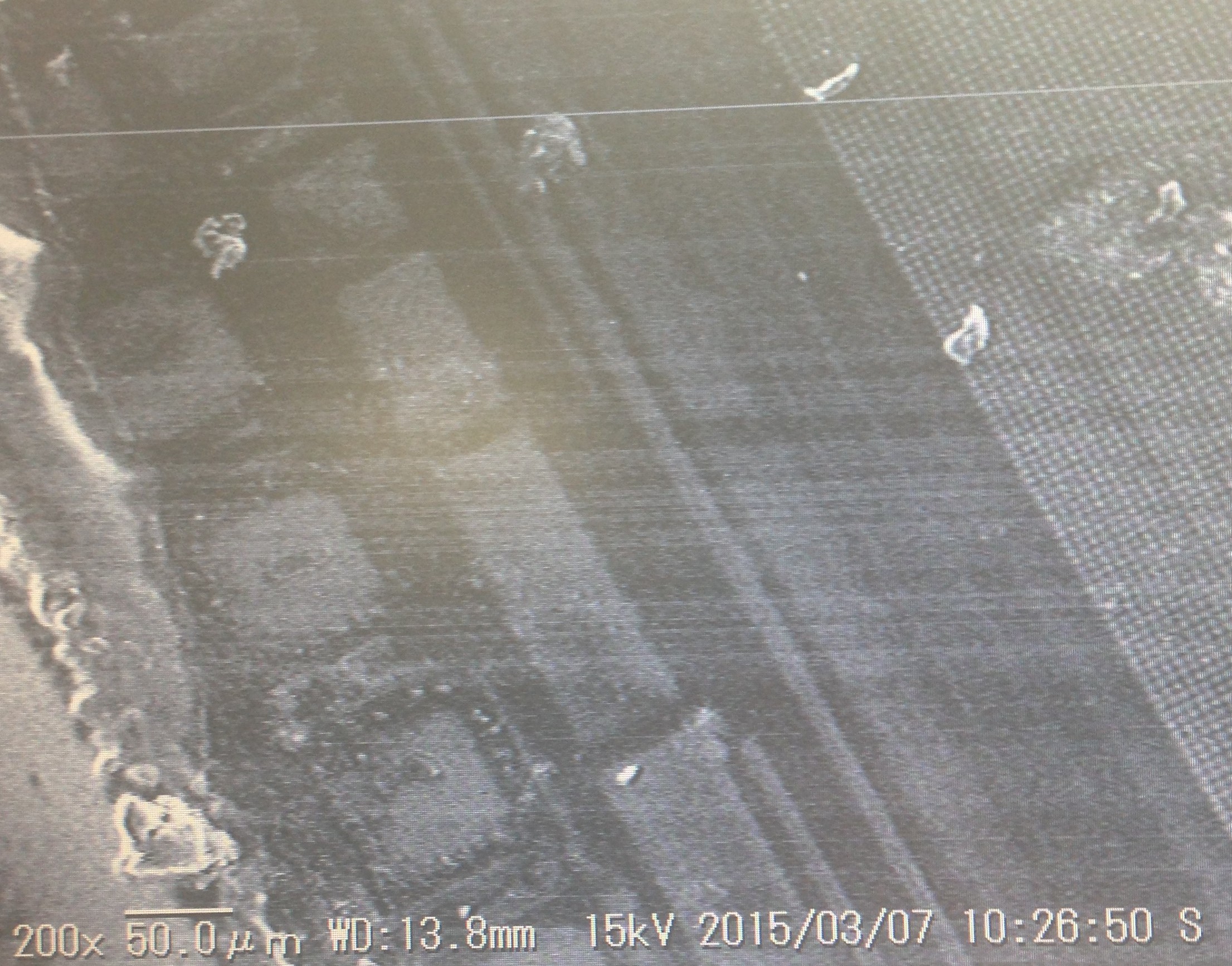
You can already get an idea of the feature sizes involved here. These is an old CCD and the lens on the right of the image are a few microns. I believe the bond pads are on the left, and between the two should be part of the shift register.
 It was interesting to note that after zooming in/out a few times we could start to see damage to the lens. It wasn’t critical in this case but you have the option of playing with the acceleration voltage to try and avoid this.
Next it was onto the really interesting stuff, one of our group had extracted and mechanically decaped a GPU.
This was if I remember correctly part of what we think is the OTP ROM:
At 9000x: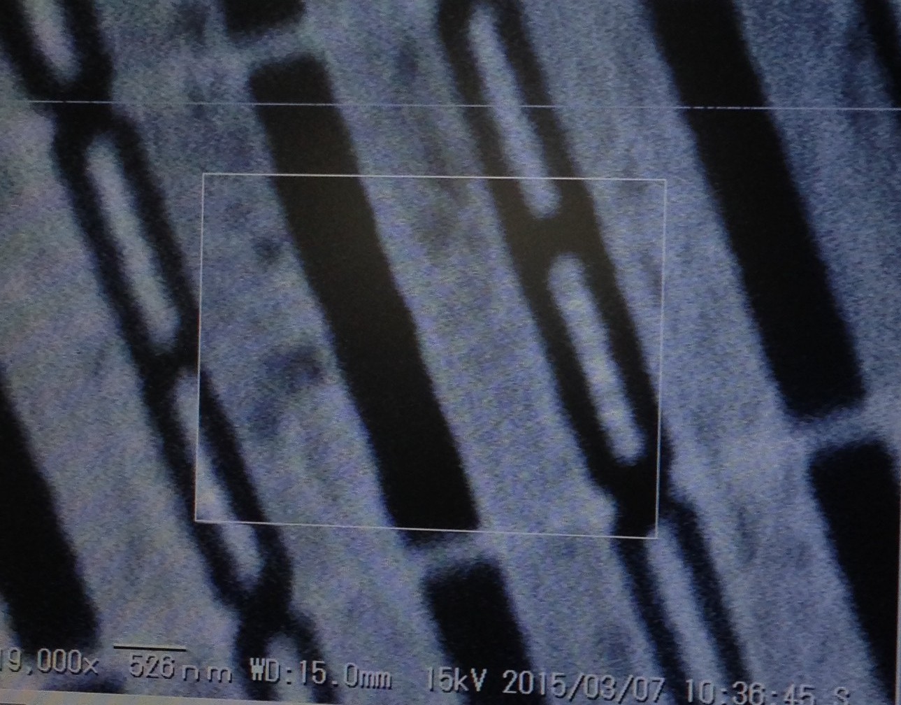
RAM:
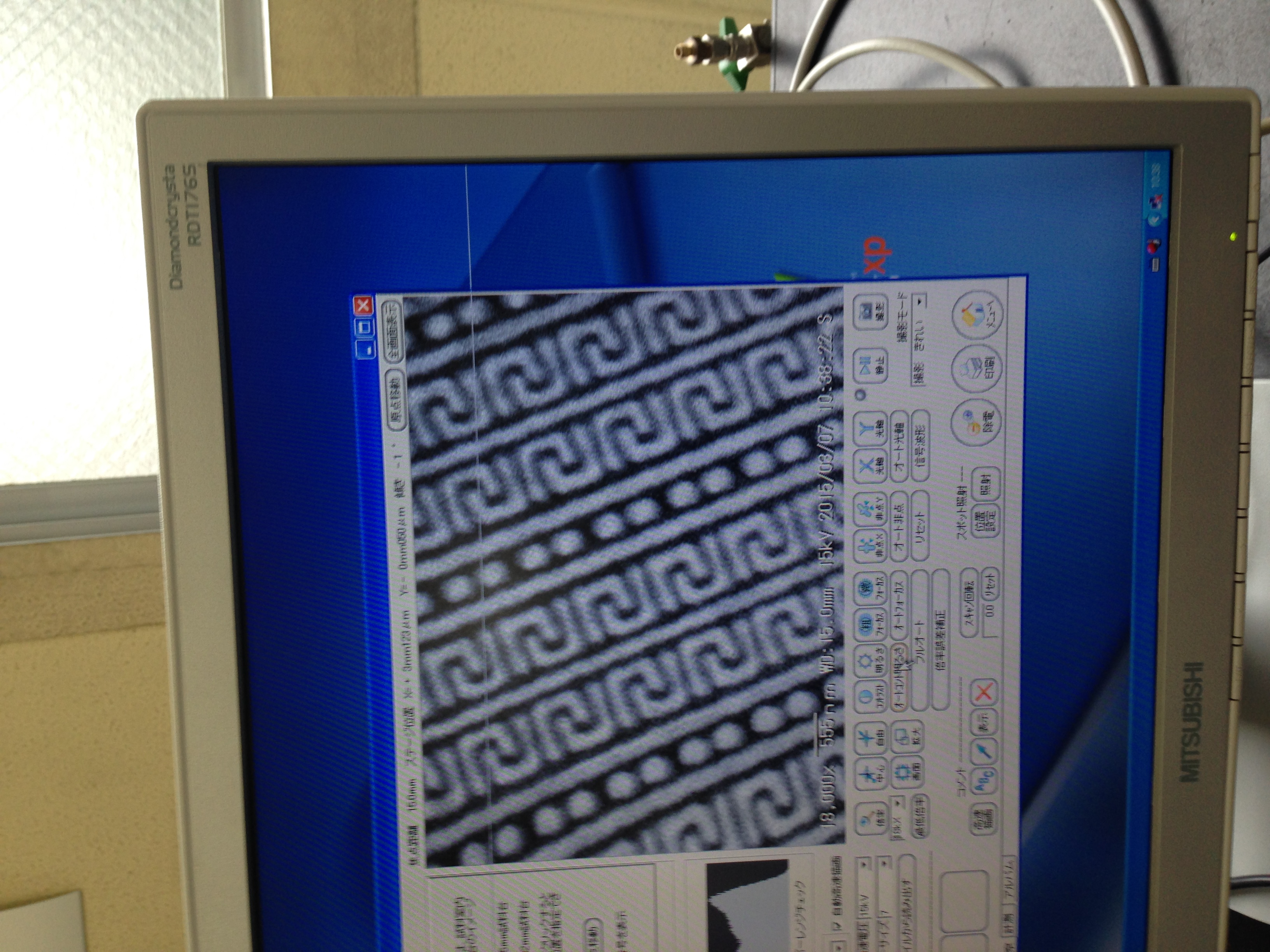
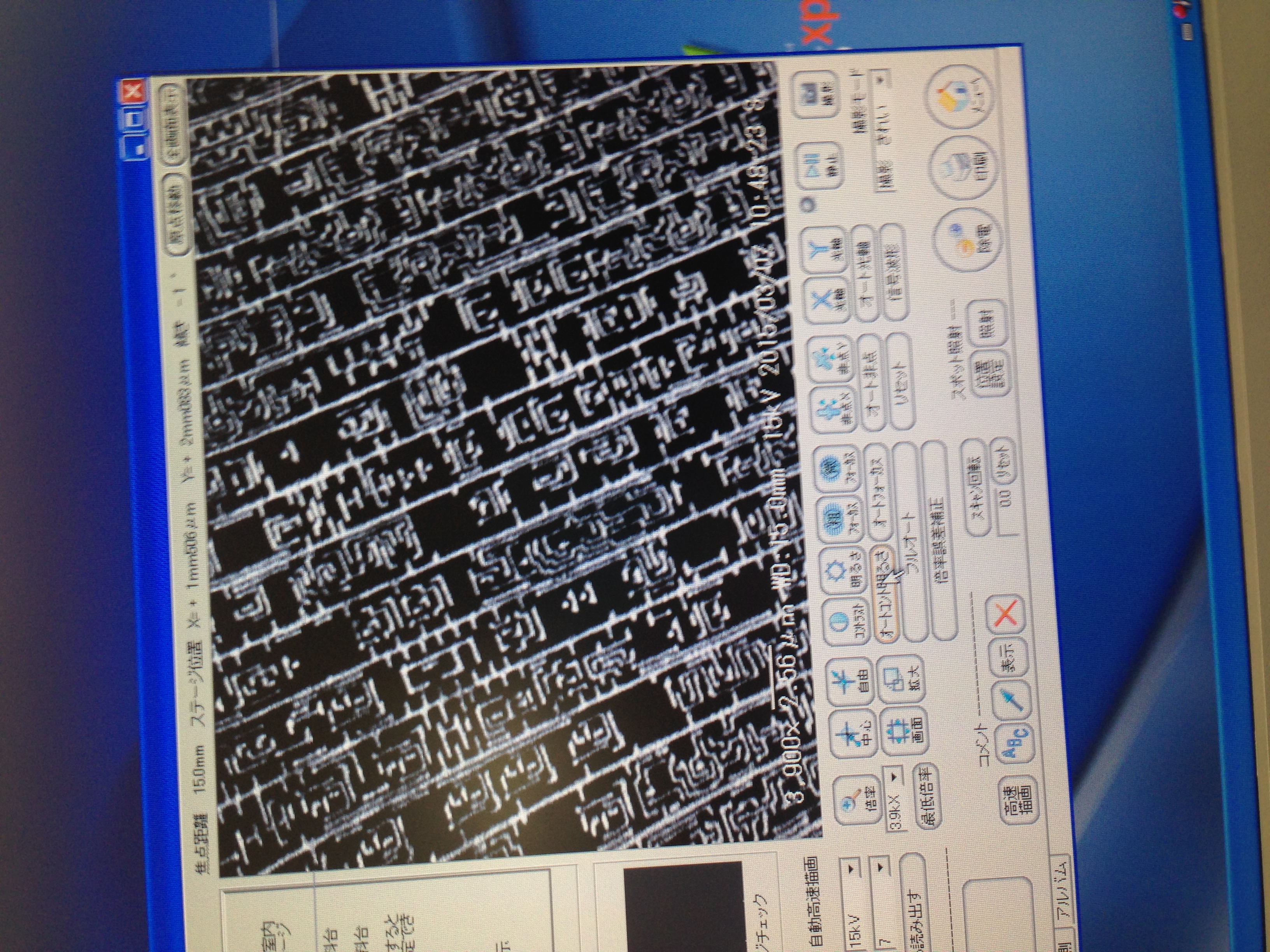
And some random logic:
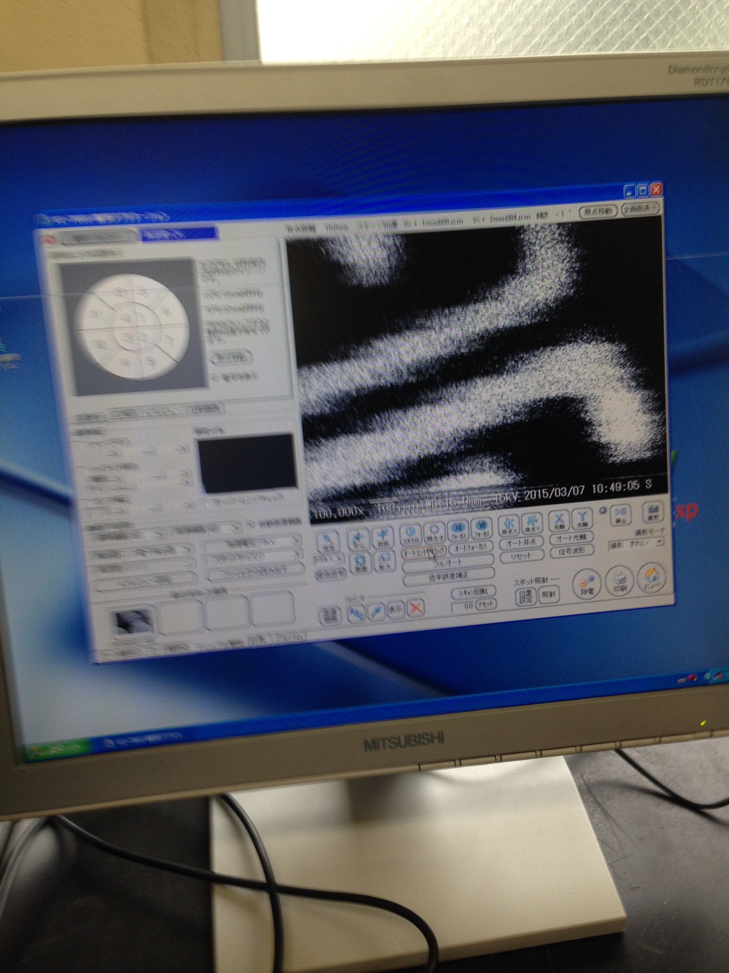
Here we are at 100000x, the features here are ~50nm:
You can take a look at the pictures Marcan took here, much better than mine.