Interfacing Chuo Seiki stages

P1000665

I finally got a chance to setup the Chuo Seiki motorized stages I bought at auction a while back. The stages use oriental motor 5 phase stepper motors (PH533s). Of course, being second hand they didn’t come with any drivers, and stepper 5-phase drivers are far less common than 2-phase ones.

I picked up an oriental motor UDK5214NW 5-phase driver. Looking at the stage it seemed that only 5 wires went to the stepper, the rest go to limit switches (I assume optical). 5 wires doesn’t seem to match with the PH533 datasheet, and the colors didn’t match those shown on the driver but I tried wiring it up anyway (I assume it uses the wiring shown below).

The most painful part of the whole process is obtaining the connectors. The stage uses HR10A-10P-12S (Hirose) connectors which cost about 20USD each. The stepper driver uses a CN1 connector which also costs about 15USD. So for an XYZ stage you’re spending 100+USD on connectors alone. It would in fact be straight forward to hack the Hirose connectors off and stick D-type connectors on but I didn’t want to mess up the stages.

Pins 1 to 5 on the HR10A appear to go to the motor. I wired these through to the stepper driver ignoring the color coding on the driver. Somewhat surprisingly this worked.

Pins 1 and 2 rotate clockwise, 3 and 4 anti-clockwise. The inputs are opto-isolated, and require a ground and signal connection.

I tried the following stages: ALV-600-H1M, ALS-602-HOM and MMU-60X-H1. They all appear to have the same pinout.

Using a 100Hz pulse it took approximately 10s to move 1mm, which sits well with the stated 1 micron resolution of these stages.

Misc. Pictures:

5phase

P1000662

P1000661

P1000660

P1000659

P1000658

P1000657

P1000656

P1000655

P1000654

P1000653

P1000652

P1000651

P1000650

P1000690

Axopatch 200A Internal Pics

I picked up an Axon instruments Axopatch 200A on ebay (it’s a patch clamp which can be used for ion channel experiments among other things). Here are some PCB pics for your viewing pleasure. No headstage pictures yet, but I’ll add them at some point [UPDATE: added below].

Late 80s early 90s electronics at its finest!

P1000647

I also took some pics of the headstage, it uses a custom can most likely with a bunch of transistor dies (like their other stages). There’s also a OPA627 opamp in there:

P1000675

P1000642

P1000643

P1000644

P1000645

P1000646

Lab workbench build notes

bench16

I’ve been setting up a new work area for my lab in Somerset. As part of this I needed to prepare some workbenches. I guess I could have bought them, but I don’t think I’d find anything that would suit my requirements at a reasonable price. So I decided to build them.

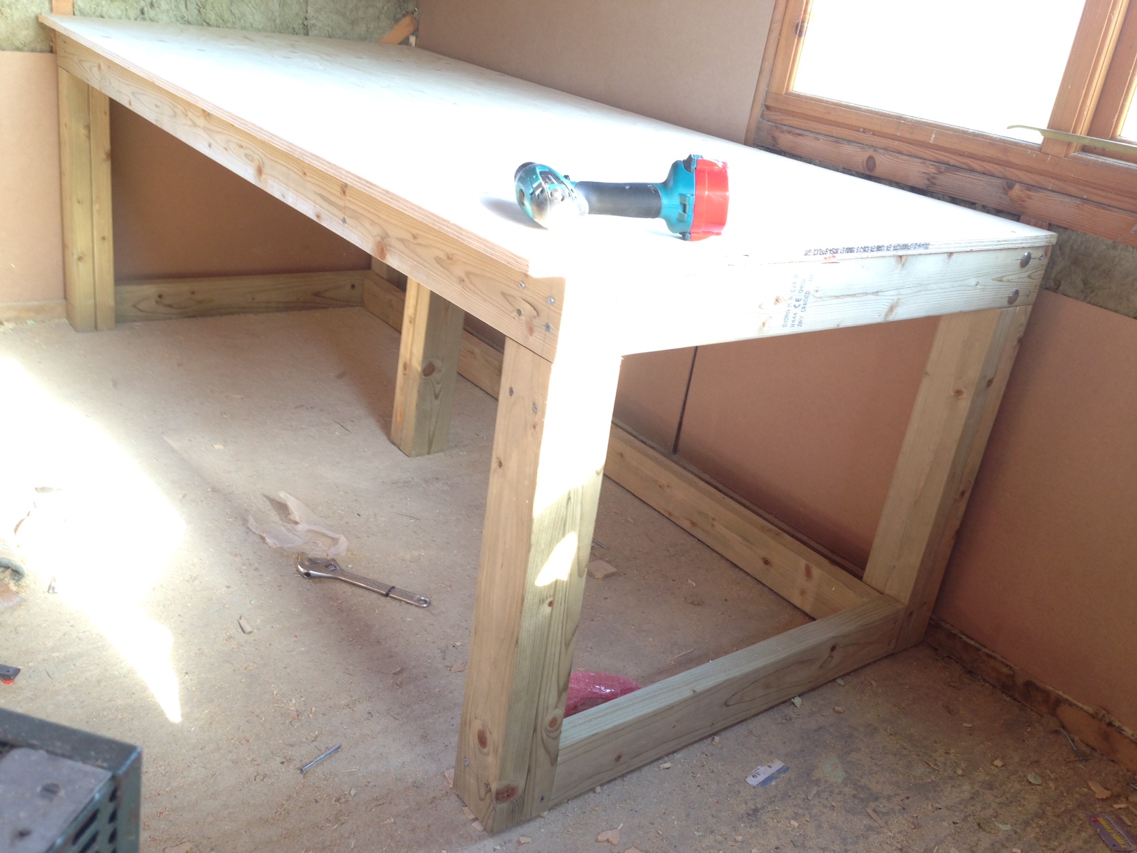
I wanted a solid bench, that would basically take anything I’d put on it. I also wanted it to be a metre deep. I tend to find that as I pile up test equipment I lose all the usable work area. By making it a metre deep I should have ample space for test equipment, and still have room to work. So the dimensions were 2 metres long by 1 metre deep.

I used this video from Mr Knackers to guide my build. I’m no woodworker, and there were some screwups along the way but I’m happy with the results. Hopefully the next bench will take less time.

My build notes follow, which will hopefully remind me what to do next time.

The bench frame is made from 2×4 whitewood timber. I bought 15 3 metre pieces on ebay though it was actually delivered by Jewsons. It cost me 100GBP delivered (~150USD). The build used 7.5 pieces, so I should have enough for 2 benches. The top is 16mm plywood which I bought from Wickes.

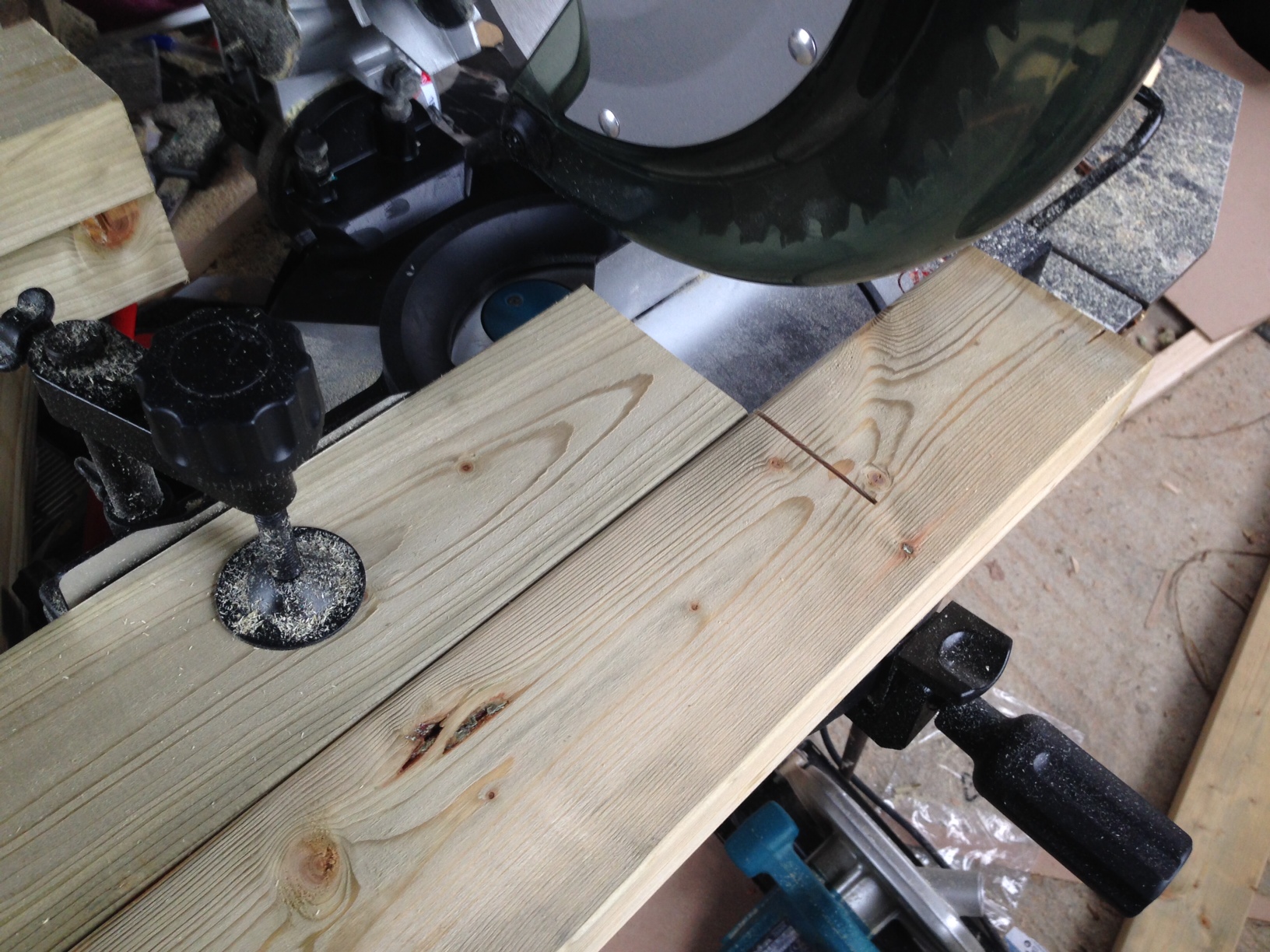
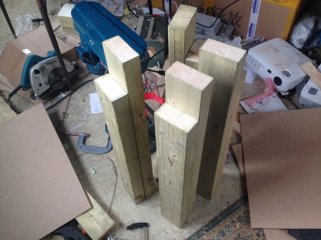
First I constructed the legs, I cut 4 lengths to 750mm-16 (734mm). And another 4 to 734mm-2inches (632.4mm). The 2 lengths are screwed together creating a notch for the frame to sit in. I cut the pieces out on a mitre saw. To make sure I got everything cut to the same length I clamped to pieces in, using my first as a reference like this:

bench5

Once all the legs are cut out, the two pieces are screwed together (two screws at the top, two at the bottom). I used 60mm screws for this.

bench17

You now need to cut an additional notch out of the larger piece so the frame will sit on the corner. You need to pay attention to the orientation of the legs when doing this. The remaining part of the longer piece will be on the inside of the bench. The shorter pieces should therefore all be facing out. 2 facing left, and 2 facing right. Otherwise things will look weird.

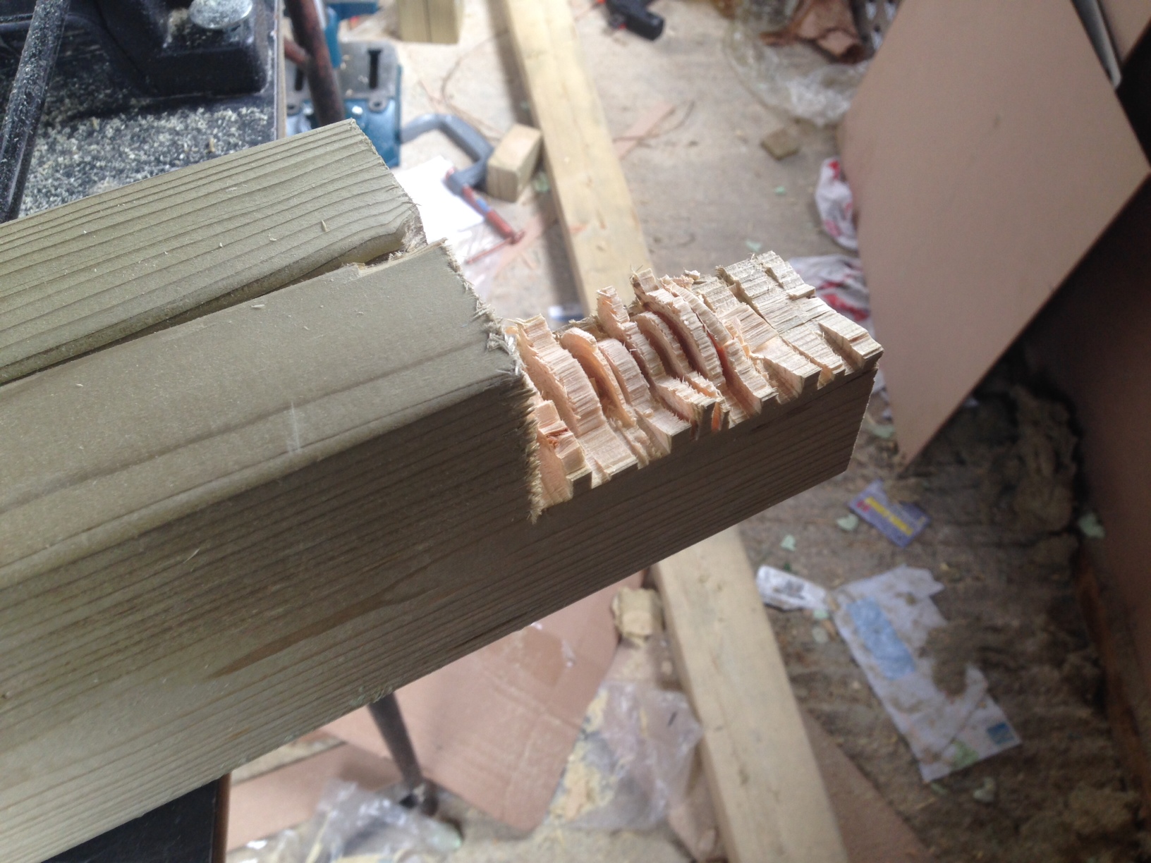
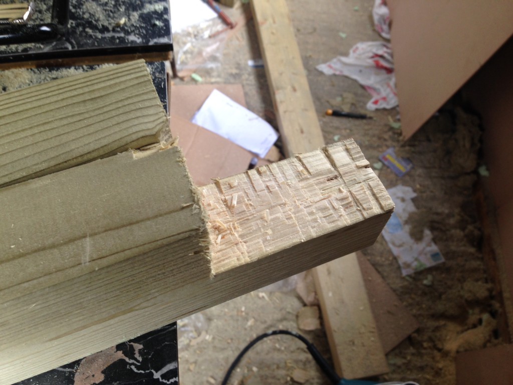
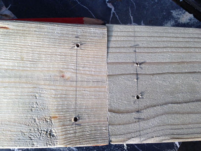
Mr Knackers suggests cutting a bunch of slots with a circular saw and then bashing them out with a chisel to cut the the longer piece down. I did this, but it was hard to get a clean finish. I’ll be looking for a new method if I do this again.

Here are the cuts made by the circular saw:
bench2

Then bashed out:
bench8

And cleaned up:
bench6

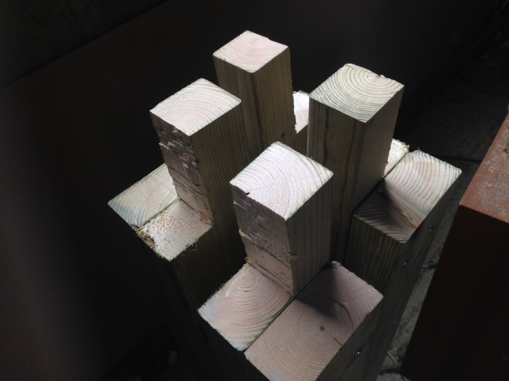
And here are all the legs with the notices cut out:

bench14

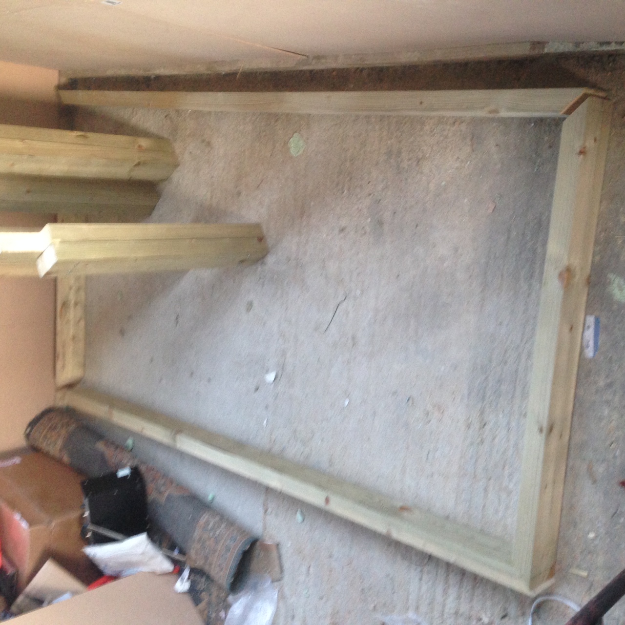
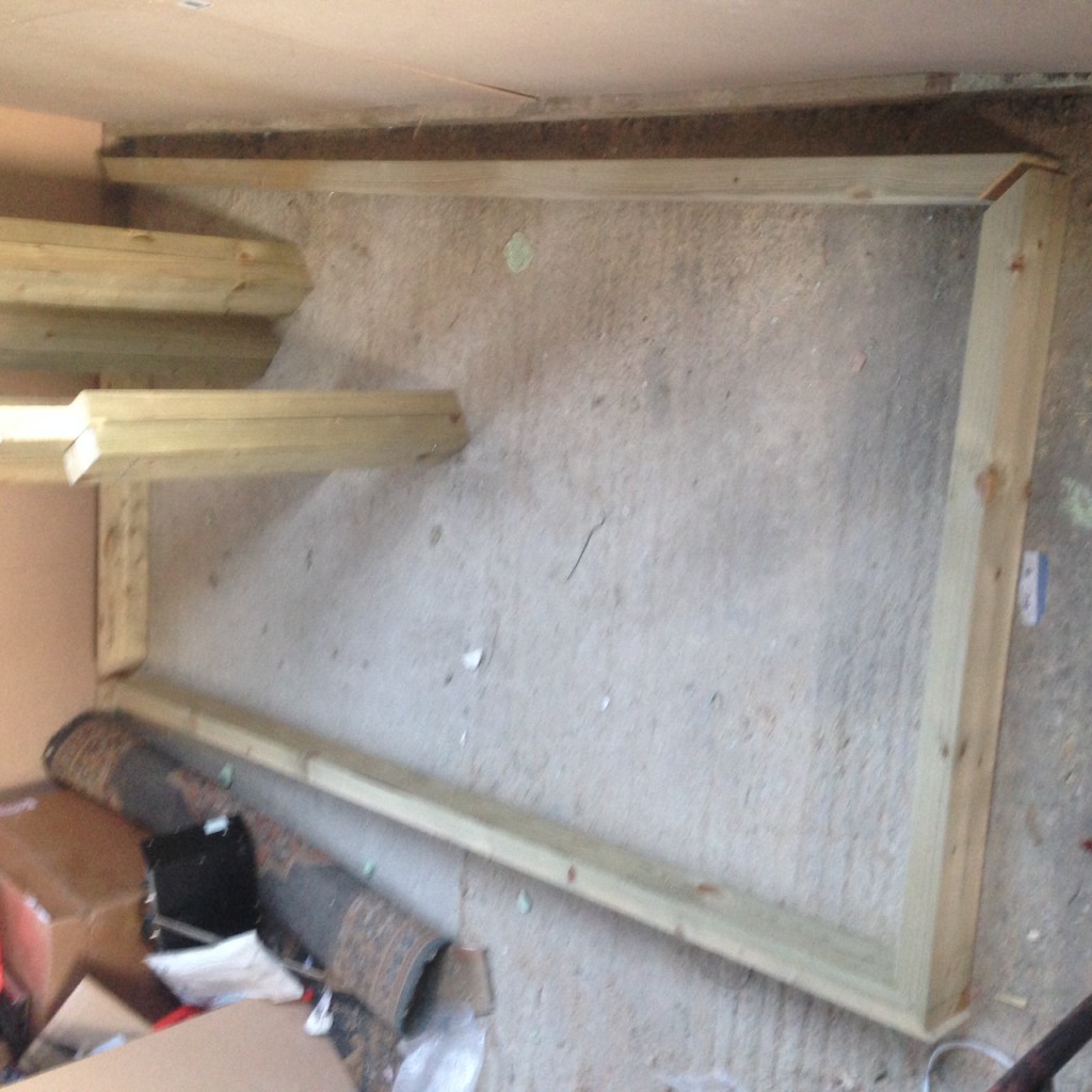
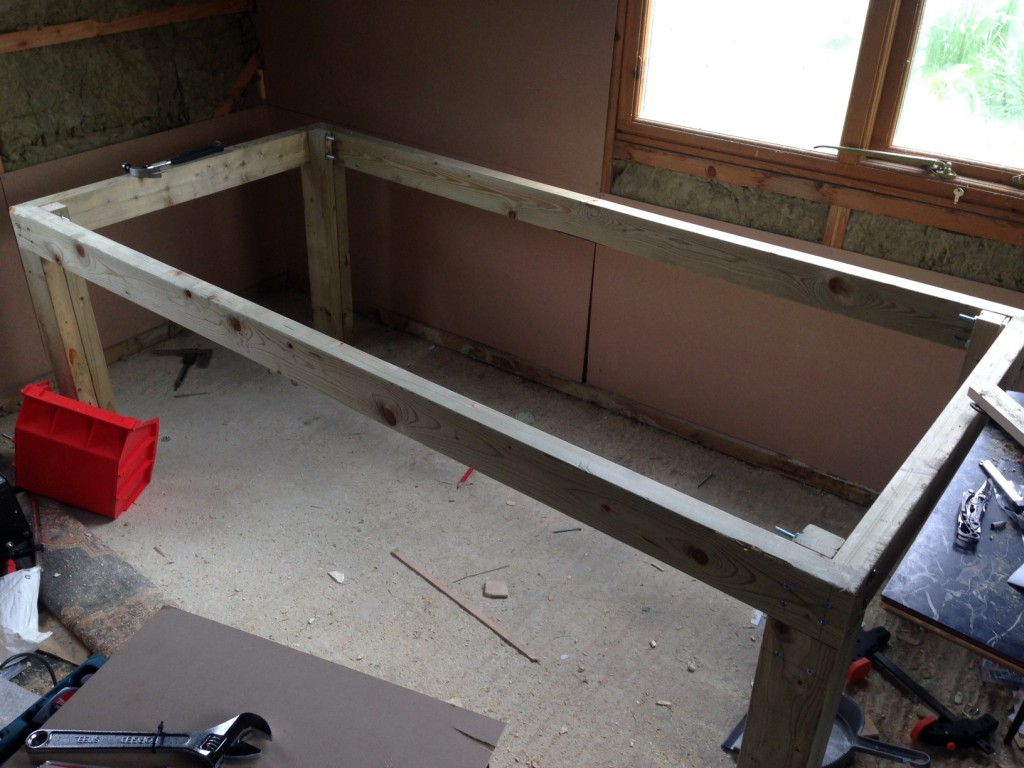
Once the legs are finished it’s time to build the frame. The outer dimensions of my frame where 2metres by 195cm as I wanted to 5cm overhang on the front for clamping things to.

The corners of the frame where cut at a 45 degree angle on the mitre saw. This gives a stronger and cleaner joint than just having the two pieces sitting at right angles.

bench7

bench15

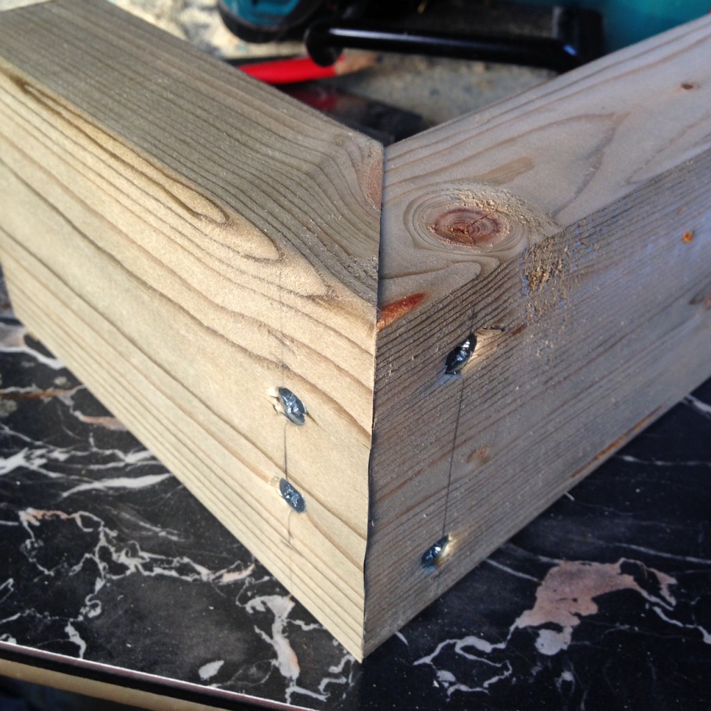
The frame is screwed together at the corners with 4 screws. These obviously need to be offset slightly:

bench9

I found it necessary to use pilot holes everywhere.

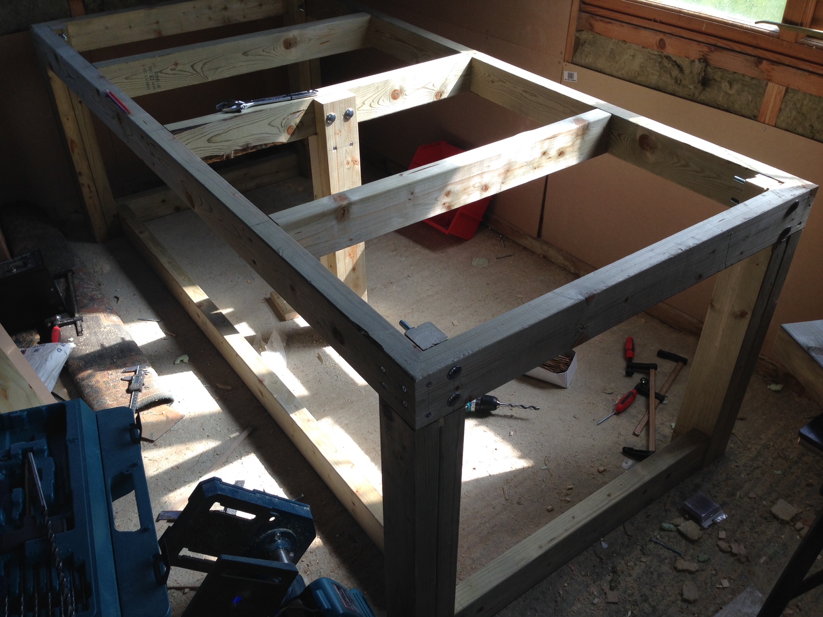
The legs can then be installed. They are screwed in to the frame on one. Alignment is important here, and I found that the cut out section was imperfect in some places. But things fit together well enough.

bench19

Coach bolts are used on the other side to fix the legs to the other edge of the frame. I used M10 bolts, and found getting them screwed in at right angles using a cordless drill problematic. Using a right angled cut in a piece of would to align the bit as it goes in seems to help. But I wonder if there’s a better way.

Next I installed additional pieces to strengthen the bench. These were held in by 2 screws on each side:

bench4

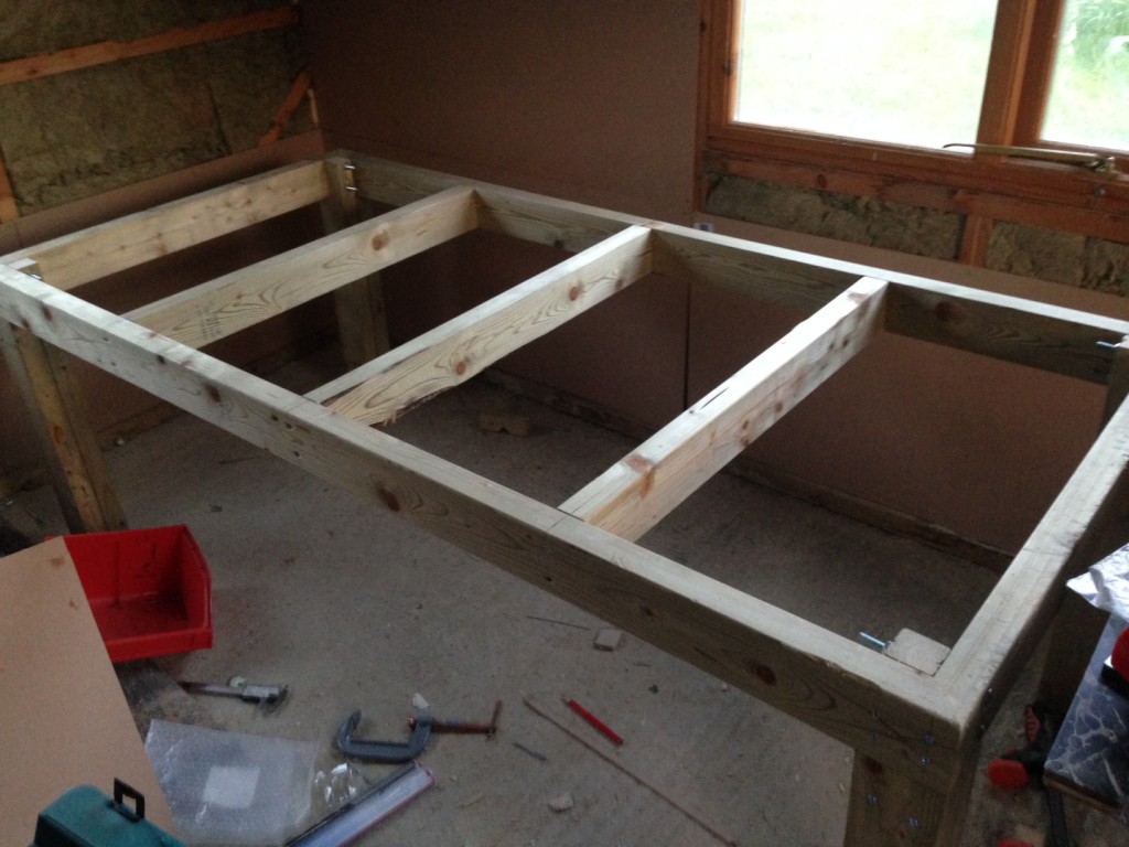
Finally I braced the legs at the back sides. The braces are only held in place by one screw each. I removed one of the screwed used to hold the legs together and replaced it with a long screw going through the leg and into the brace. I wasn’t particularly happy with this and may add another screw here. I also added a central leg to take any weight in the middle of the bench. I felt this might be required as it’s so deep.

bench10

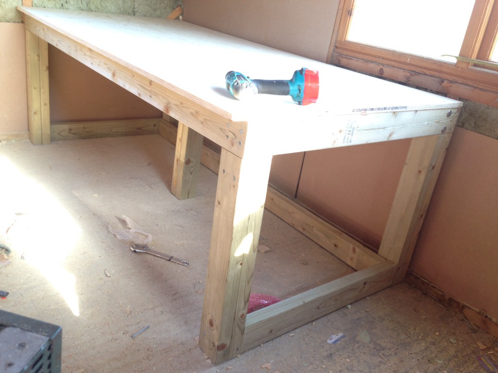
Finally I cut down the plywood with a circular saw, clamping a piece of wood to the plywood to align the saw. This was then glued and screwed down.

bench12

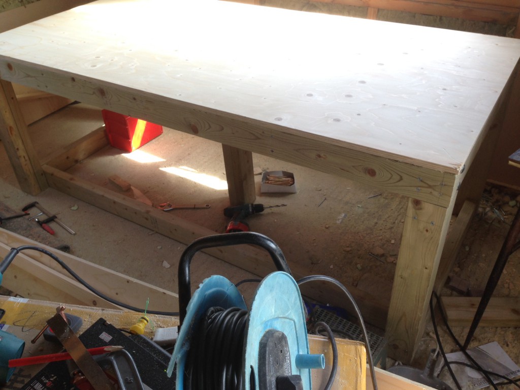
Overall I’m happy with the results and it appears to take a bunch of weight:

bench20

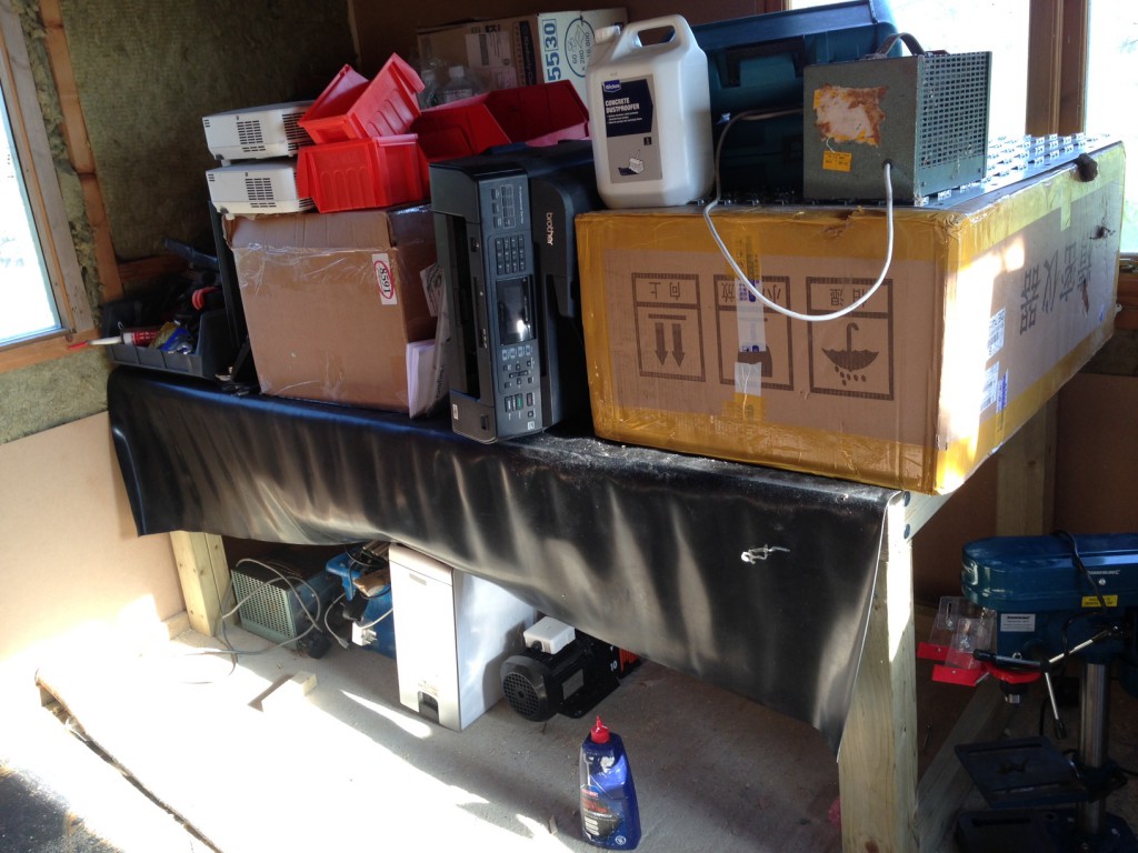
I plan to build another one, and when I finally get to use it may add a rubber mat covering and trim to protect the plywood.

In-place Radix sort O(k) space overhead

The following code implements an in-place Radix sort with O(k) space overhead. It currently doesn’t deal with signed values however that should be relatively easy to add this, the high bit just needs to be sorted in reverse order.

Unlike comparison sorts Radix sort only operates on integers with a complexity linear in the terms of the number of elements in the list (n) as a multiple of the number of digits in the integer. The implementation below operates in base 2.

This implementation sorts each bit in turn starting with the most significant bit. It operates by maintaining pointers to the top and bottom (I term them left and right below) of the array shuffling those elements with one at the current bit position to the left and zero to the right. It does this by swapping elements each time it encounters a pair in the wrong place and moving the left and right pointers toward each other until they meet.

While this sorts a single bit position, in order to sort the entire array the algorithm proceeds recursively. Once the one’s and zero’s have been sorted in the current position the Radix sort proceeds to sort all the one’s for the next lowest bit, and all the zero’s for the next lowest bit separately. While most easily described recursively, the implementation keeps track of the partitions in a vector and sorts these in a loop.

The implementation below keeps track of all the bin partitions, and thus space overhead is O(2^k) where k is the number of digits. A recursive solution would possibly be more efficient, as the algorithm would not need to keep track of all partitions down to the final bit.

#include <iostream>
#include <vector>
#include <stdint.h>
#include <stdlib.h>
#include <stdio.h>

using namespace std;

int bits = 32;

void dump_array(vector<int32_t> array);
void bin_dump(int32_t v);
void inplace_radix_sort_bit(vector<int32_t> &a,int start,int end,int bit,int &breakpoint);

void swap(vector<int32_t> &a,int l,int r) {

  int32_t x = a[l];
  a[l] = a[r];
  a[r] = x;
}

bool bit_is_set(int32_t v,int bit) {
  if((v & (1 << bit)) > 0) return true;
                      else return false;
}


void inplace_radix_sort(vector<int32_t> &a) {

  int breakpoint;
  vector<int> breakpoints;

  inplace_radix_sort_bit(a,0,a.size(),bits-1,breakpoint);
  breakpoints.push_back(0);
  breakpoints.push_back(breakpoint);
  breakpoints.push_back(a.size());

  for(int bit=bits-2;bit>=0;bit--) {

    cout << "breakpoints: ";
    for(int n=0;n<breakpoints.size();n++) cout << breakpoints[n] << " ";
    cout << endl;

    vector<int> newbreakpoints;
    for(int n=0;n<breakpoints.size()-1;n++) {
      if(breakpoints[n] != breakpoints[n+1])
     // inplace_radix_sort_bit(a,breakpoints[n]+1,breakpoints[n+1],bit,breakpoint);
      inplace_radix_sort_bit(a,breakpoints[n],breakpoints[n+1]-1,bit,breakpoint);
      newbreakpoints.push_back(breakpoint);
    }

    // create new breakpoint list (equiv for recursion)
    vector<int> mergebreakpoints;
    for(int n=0;n<breakpoints.size();n++) {
      mergebreakpoints.push_back(breakpoints[n]);
      if(n!=(breakpoints.size()-1)) mergebreakpoints.push_back(newbreakpoints[n]);
    }
    breakpoints = mergebreakpoints;

    // remove duplicates
    vector<int> cleanedbreakpoints;
    cleanedbreakpoints.push_back(breakpoints[0]);
    for(int n=1;n<breakpoints.size();n++) {
      if(breakpoints[n] != breakpoints[n-1]) cleanedbreakpoints.push_back(breakpoints[n]);
    }
    breakpoints = cleanedbreakpoints;
  }

}

void inplace_radix_sort_bit(vector<int32_t> &a,int start,int end,int bit,int &breakpoint) {

  // sort each bit posiiton

  cout << "sorting bit: " << bit << "  pos: " << start << " " << end << endl;
  int l_pos = start;
  int r_pos = end;

  for(;l_pos < r_pos;) {
    cout << "l_pos: " << l_pos << " r_pos: " << r_pos << endl;
    cout << "comparing: " << a[l_pos] << " " << a[r_pos] << " ";
    bin_dump(a[l_pos]);
    cout << " ";
    bin_dump(a[r_pos]);
    cout << endl;
      
    bool l_bit = bit_is_set(a[l_pos],bit);
    bool r_bit = bit_is_set(a[r_pos],bit);
    if(l_bit) cout << "l_bit: 1" << endl; else cout << "l_bit: 0" << endl;
    if(r_bit) cout << "r_bit: 1" << endl; else cout << "r_bit: 0" << endl;

    if(!l_bit &&  r_bit) { swap(a,l_pos,r_pos); l_pos++; r_pos--; cout << "swp"          << endl; if(l_pos == r_pos) if(bit_is_set(a[l_pos],bit)) {l_pos++; break;}} else
    if( l_bit && !r_bit) {                      l_pos++; r_pos--; cout << "10 linc rdec" << endl; } else
    if( l_bit &&  r_bit) {                      l_pos++;          cout << "11 linc"      << endl; if(l_pos == r_pos) {l_pos++; break;}} else
    if(!l_bit && !r_bit) {                               r_pos--; cout << "00 rdec"      << endl; if(l_pos == r_pos) { break;}}
  }
  breakpoint = l_pos;
  dump_array(a);
}

void bin_dump(int32_t v) {

  for(int n=bits-1;n>=0;n--) {
    if(v & (1 << n)) cout << "1"; else cout << "0";
  }

}

void dump_array(vector<int32_t> array) {
  
  for(int n=0;n<array.size();n++) {
    printf("%20d ",array[n]);
    bin_dump(array[n]);
    cout << endl;
  }

}

int main() {

  vector<int32_t> array;
  for(int n=0;n<20;n++) {
    array.push_back(rand());
  }

  cout << "random array" << endl;
  dump_array(array);

  inplace_radix_sort(array);

  cout << "sorted array" << endl;
  dump_array(array);
}