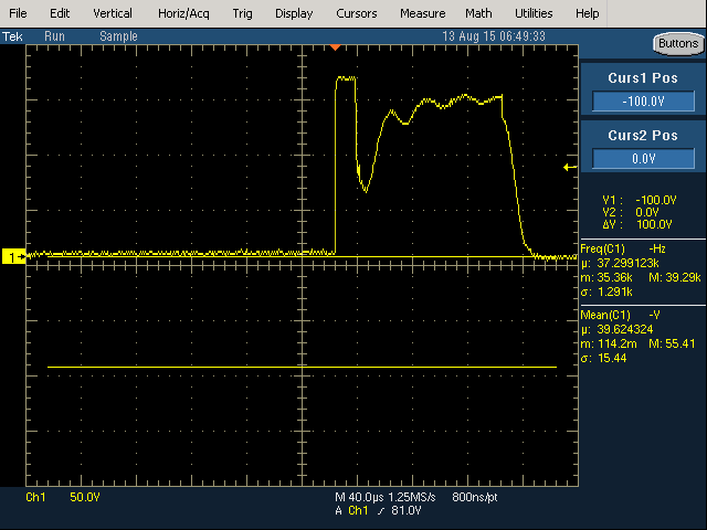
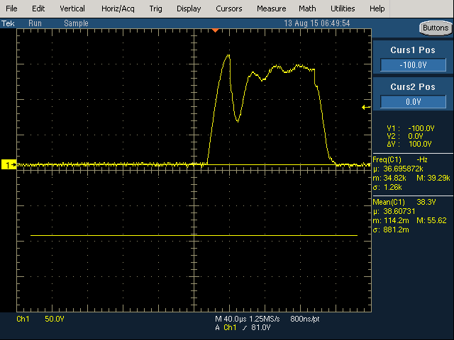
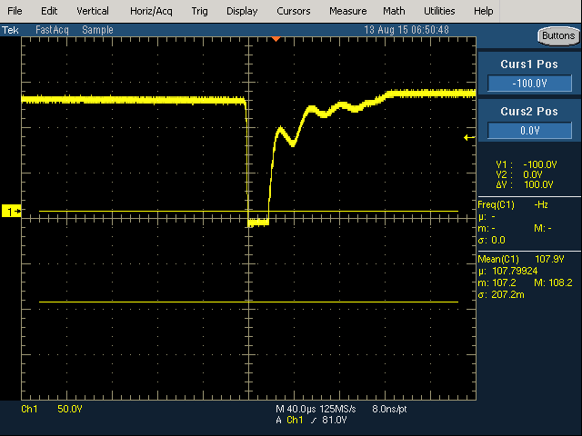
Picomotor driver scope traces
I previously posted about getting the picomotor up and running. Picomotors are awesome little motors which provide 30 to 100 nanometer resolution without gearing. Anyway, I cleverly almost blew it up the driver other day, by sticking 15 volts into the 5v line. A repair would be tractable, as it’s all discrete 1980s logic, however luckily all I need to do is change one of its many fuses.
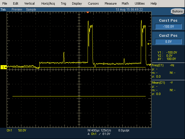
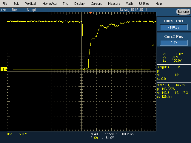
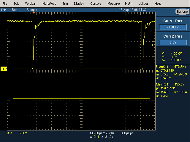
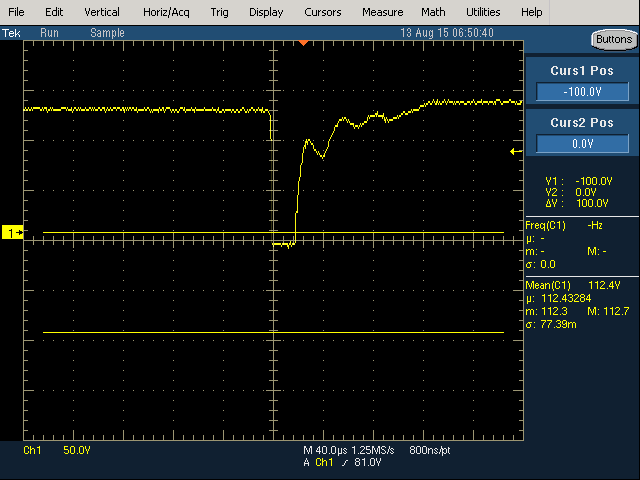
Anyway, I really don’t ever want to by another driver, as it was too expensive for a bunch of 74 series logic and some big inductors. So I figured I’d grab some waveforms just in case I ever decide to build one. The waveforms however are somewhat confusing… my understanding is that when moving in one direction I should see a sort pulse, followed by a long pulse. In the other direction a long followed by a short. That’s not really what I saw. The baseline appeared to shift between forward and reverse motion. And it didn’t look like the pulses changed order… I may revisit this in the future and grab some more traces. But the useful information is that the driver uses 150v to drive the stack, short pulse width is ~20us, long ~100us. Maybe…
[UPDATE: I think my non-sleep deprived brain understands these traces a little better basically we’re interested in the rise and fall time, not the durations of the traces. So I think these traces make sense, in the first set we have a fast rise time and a slow fall, the second fast fall, slow rise. The fact that the baseline I don’t think matters too much, though there’s probably a reason for this that I don’t yet fully understand]
+/- 15V and 5V REF board
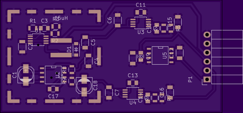
This is a first pass at a power supply board for use with the AD5791 DAC board. It should run from 3v up. It uses an LM3224 to boost the 3v to +/- 16V and a MAX889 to invert this to give -16V. TPS7A3001 and TPS7A4901 linear regulators are used in an effort to avoid any switching noise and regulate down to +/- 15V. The board also contains an ADR445 5V reference for the DAC. The switching components sit under an RF shield. I’m hoping that helps reduce noise in the system.
Out to fab, fingers crossed it works!
[UPDATE] Already found out the MAX889 is the wrong part. Only goes to 8V. Will be trying a LT1054.
New LT1054 version: powerbrd.tar
Old MAX889 version: powerbrd.tar
AD5791 Arduino Shield
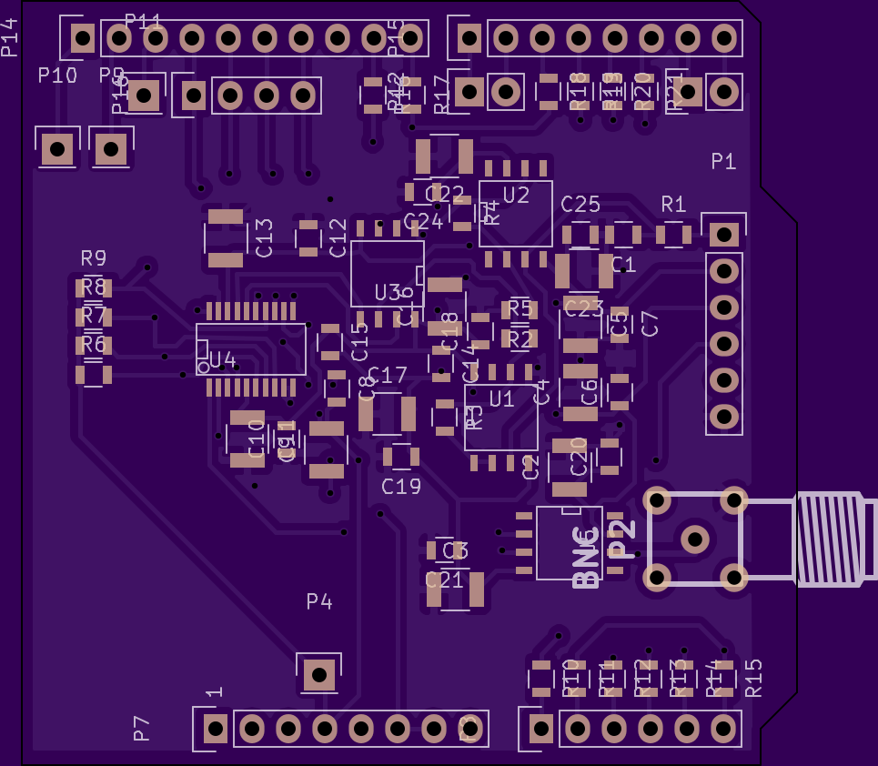
[UPDATE: Current version is HERE]
I’ve made a first pass at an AD5791 20bit DAC Shield. It’s out to fab and I’ll update this page as the project progresses. Kicad files below. I’ve already noticed some issues (AGND, and DGND not connected, should be connected near the DAC) so they’ll be some patches for testing and a respin at some point.