September 1, 2016, 3:54 am
 Yesterday I was working on the mirror switch which is a network switch with static port mirroring config. This basically mirrors all traffic on one port to a second interface which lets you monitor and inspect traffic.
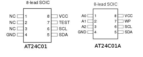
The switch loads config from a small EEPROM. The datasheet specifies a 24C01~16… I picked up some more AT24C32s which looked compatible with the AT24C01A and ordered a few AT24C01As… of course it didn’t work. Which led me down the rabbit hole.
These EEPROMs use a 2-wire protocol, basically serial clock and an I/O pin that switches between input and output based on the serial instruction. I spent some quality time with a scope trying to figure out why exactly the AT24C32 wasn’t working. It’s a 2-wire EEPROM in the same series… seemed like it should work.
After some head scratching I looked again at the datasheet. It specifies a 24C01… no A… The AT24C01 has long been deprecated by Atmel. But looking at the parts the AT24C01 and AT24C01A seem similar… largely compatible pinouts (just some added address lines)… they have the same function…
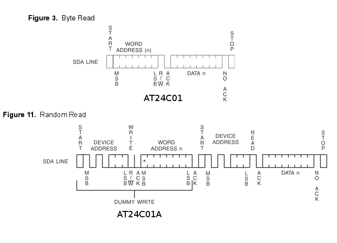
Protocol differences between the at24c01 and at24c01a
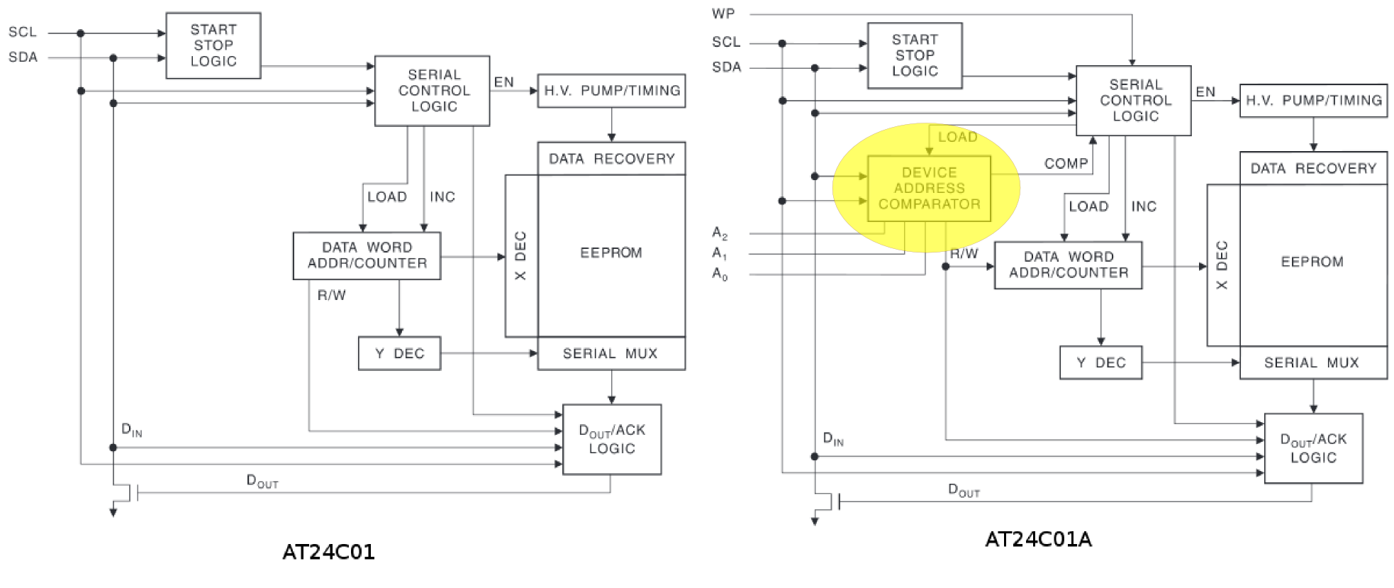
Differences in the block diagrams..
But the protocol is different. Somewhere between the AT24C01 and AT24C01A Atmel decided that they needed per device addressing. Each command sent to the device therefore includes the device address, making the part non-backward compatible.
What’s interesting is that AT24C01 style parts are still being used in current generation products in Shenzhen. You can find knockoff AT24 C01s as jellybean parts on taobao. My guess is that somewhere around the release of the AT24C01 the ecosystem decided to standardize on this for a bunch of products and that was that.
Outside of Shenzhen things moved on, while Microchip has a great compatibility chart showing common devices compatible with the AT24C01, almost none are available (in fact many of the companies they mention don’t even exist anymore). There’s a single part on digikey which looks like it should be compatible… the 24AA01. Which is on it’s way to me… I live in hope (UPDATE: neither the 24AA01-I/SN-ND or 14C01BT-I/SNCT-ND which I purchased from digikey appear to be compatible despite the compatibility matrix saying they are, closer inspection of the datasheet kind of implies this, I’m working on another solution).
What’s interesting to me is that all this is probably common knowledge in Shenzhen, and a 5min chat at a EEPROM booth would probably reveal all… but for me it’s half a day of debugging. 🙂
August 31, 2016, 2:58 am
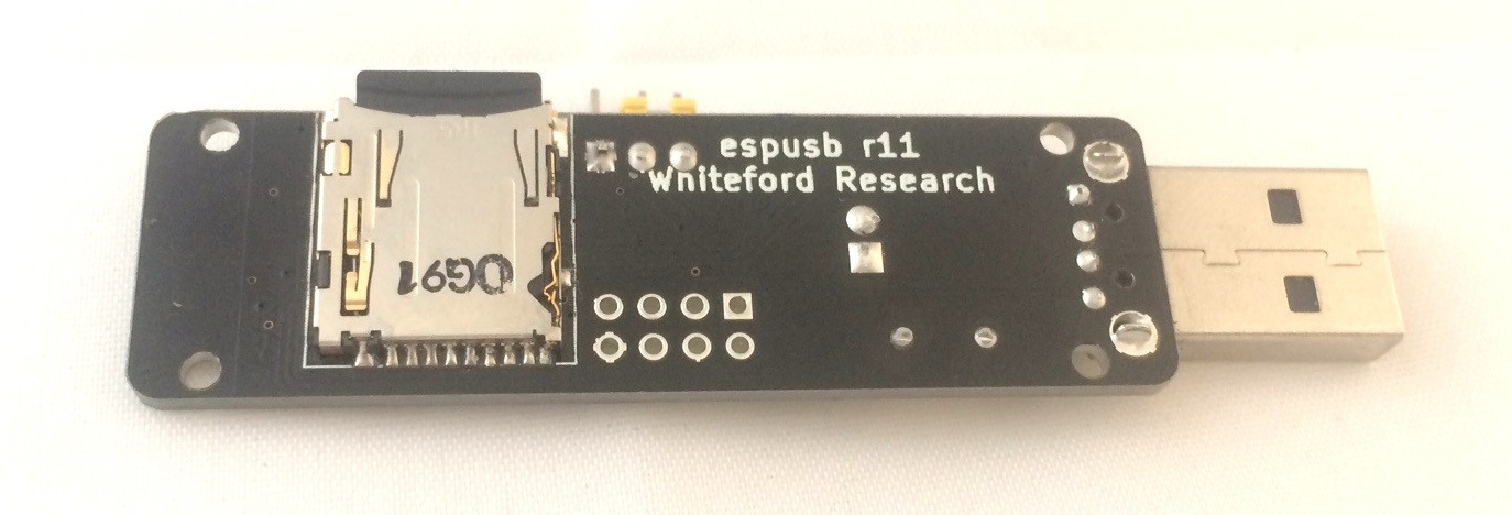
 Recently I’ve been using the esp8266 with SD cards in order to develop the small board shown above and to the right. It hosts a CH340g USB interface, small buck converter to supply 3.3v to the esp8266 and an SD card slot.
The esp8266 is pretty thin, and doesn’t really give the information necessary to get up and running, so it took some research and hacking around to get everything working.
A lot of this was motivated by this forum thread which provided that it was possible to get SD cards working on the esp8266 using the SPI interface. SD cards generally use a more complex protocol and multiple data lines, but they can fall back to SPI mode (albeit with reduced performance).
The Arduino esp8266 support pack also has done great work, and after configuring a chip select pin, the SD card library supplied there pretty much just works.
I wanted to use the native esp8266 SDK without the Arduino environment. This took some hacking, but so far I’ve extracted the SD card library and have it up and running using a native SPI driver, the main issue was enabling (the again undocumented) duplex mode of the esp8266 SPI interface. If you’d like a copy of this code ping me.
One final note, some documents refer to “SD Card” boot mode. That would be really cool, to be able to load your firmware directly from an SD Card. Unfortunately it’s a bit of a misnomer. “SD Card” mode actually refers to SDIO mode. We don’t really hear much about SDIO anymore, but you used to be able to buy these funky Wifi cards which plugged into SD card slots. Other peripherals, like cameras were available too. You can read more about it on the wikipedia page.
The esp8266 supports an SDIO boot mode. My guess is that this is a hang over from its heritage as a general purpose Wifi interface chip. Some people have used this functionality to enable firmware loading over SPI. It’s neat, but unfortunately doesn’t mean you can boot from a standard flash SD card.
PLUG: I’m now selling the esp8266 SD card board above on my shop. My hope is to eventually progress this toward a consumer product which runs an access point and provides basic collaboration tools.
August 26, 2016, 1:48 pm
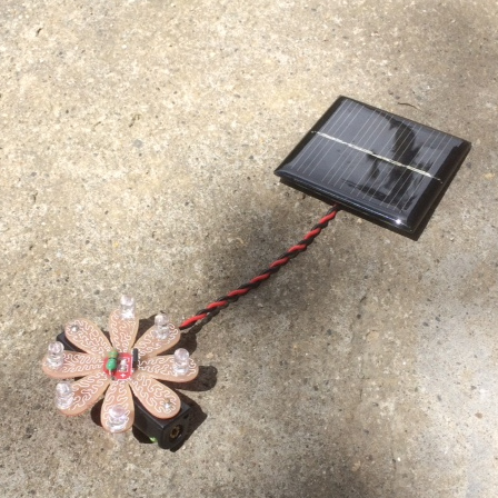
I’ve been playing with these simple Solar lantern controller ICs recently. They’re the chips used in most cheap solar garden lights. Akiba and I have built a couple of products around these chips and have more in the works.
They’re pretty amazing ICs given that they cost almost nothing and contain a complete NiMH charge controller, boost converter, and PWM LED driver.
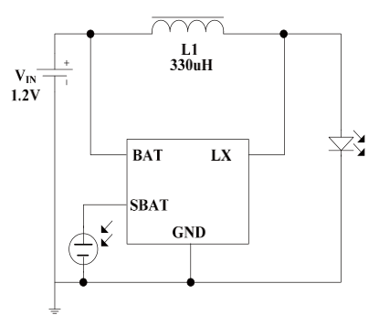 The basic circuit from the datasheet is shown to the left, and aside from the IC itself you just need to add a single inductor, NiMH battery, solar cell and of course the LEDs to complete the circuit.
It uses the solar cell both to charge the battery and as a light sensor. When voltage from the solar cell falls below 150mV the IC will switch into illumination mode and start powering the LEDs. Rather than a typical current limiting configuration, the IC slightly overdrives the LEDs but uses a 100KHz pulse-train to drive them which they suggest results in >90% efficiency.
Considering the IC basically costs nothing this is pretty impressive. I have a set of 10 ICs+inductors on my shop if anybody else wants to play with them.
August 24, 2016, 4:15 am
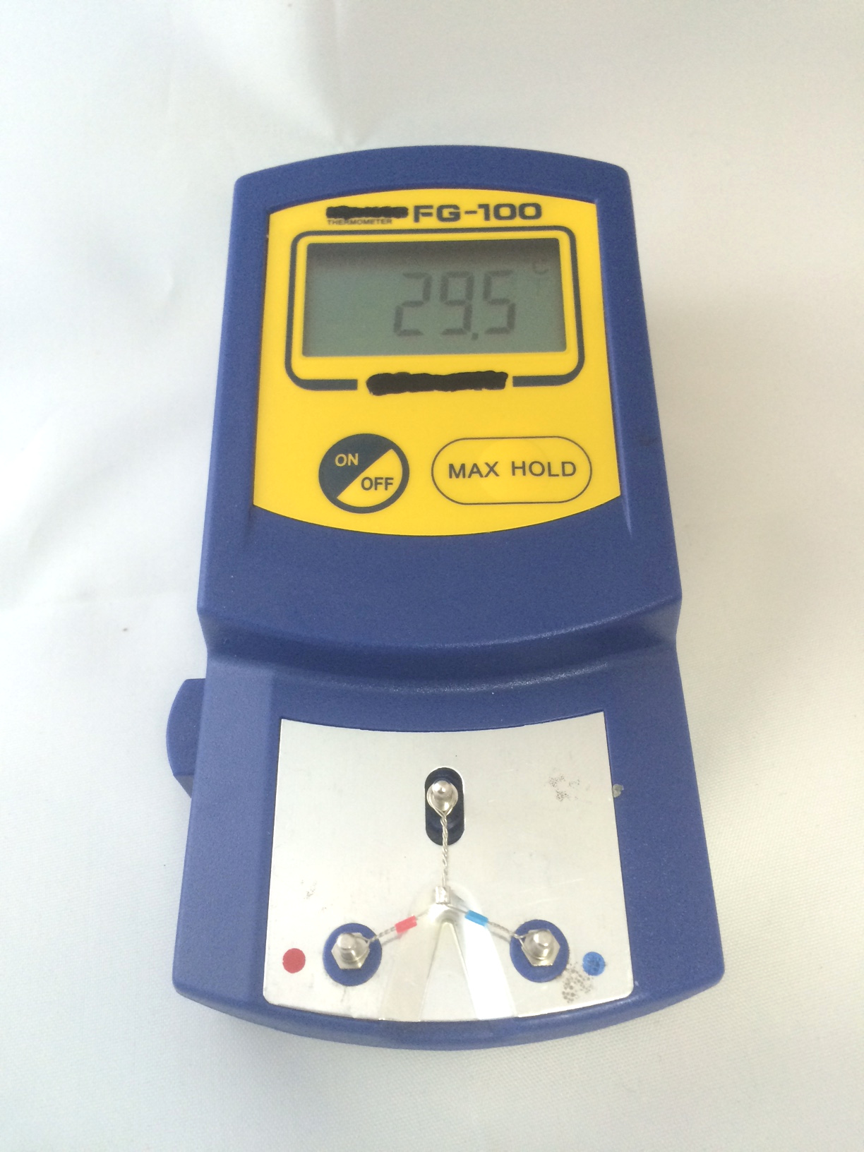
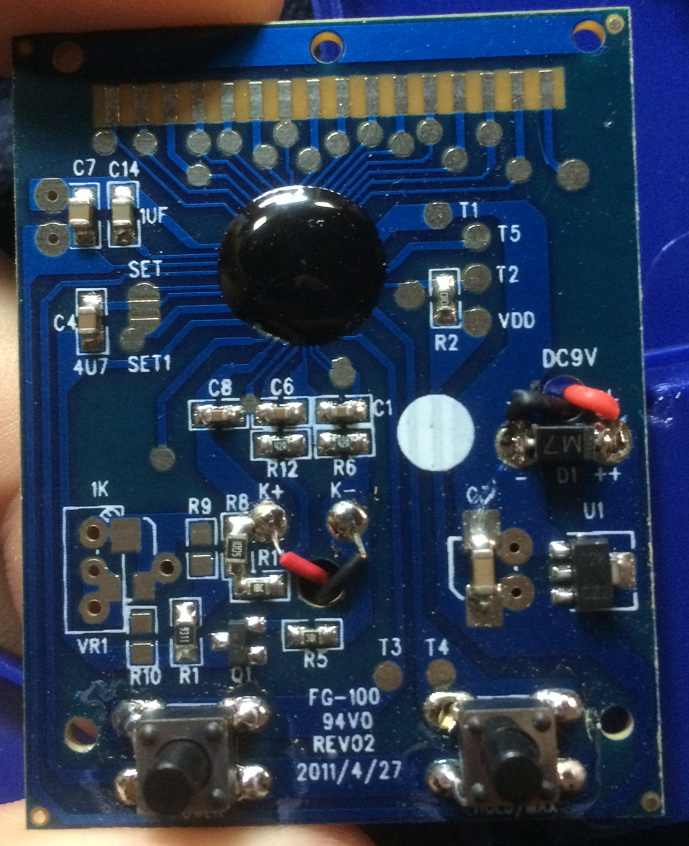
I picked up this cheap soldering iron temperature sensor. I mostly wanted it to check the heat capacity of the various tips I have. I was disappointed that it came with Hakko branding, the supplier just listed it as an FG100 (which is a Hakko model number) but it’s clearly fake.
It does however work pretty well, and I was able to see clear differences between my T12-D12 (1.2mm) tip and T12-D24 (2.4mm). I’ll be performing further tests to see how well the various tips perform and see if I can more accurately gauge the heat capacity of the tips. I also want to use this to check the calibration of cheap Hakko 936 clones that I’ve been picking up from Shenzhen for running workshops.
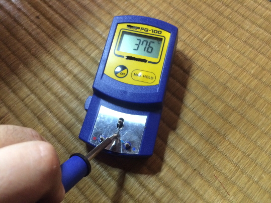
T12-D24 Tip
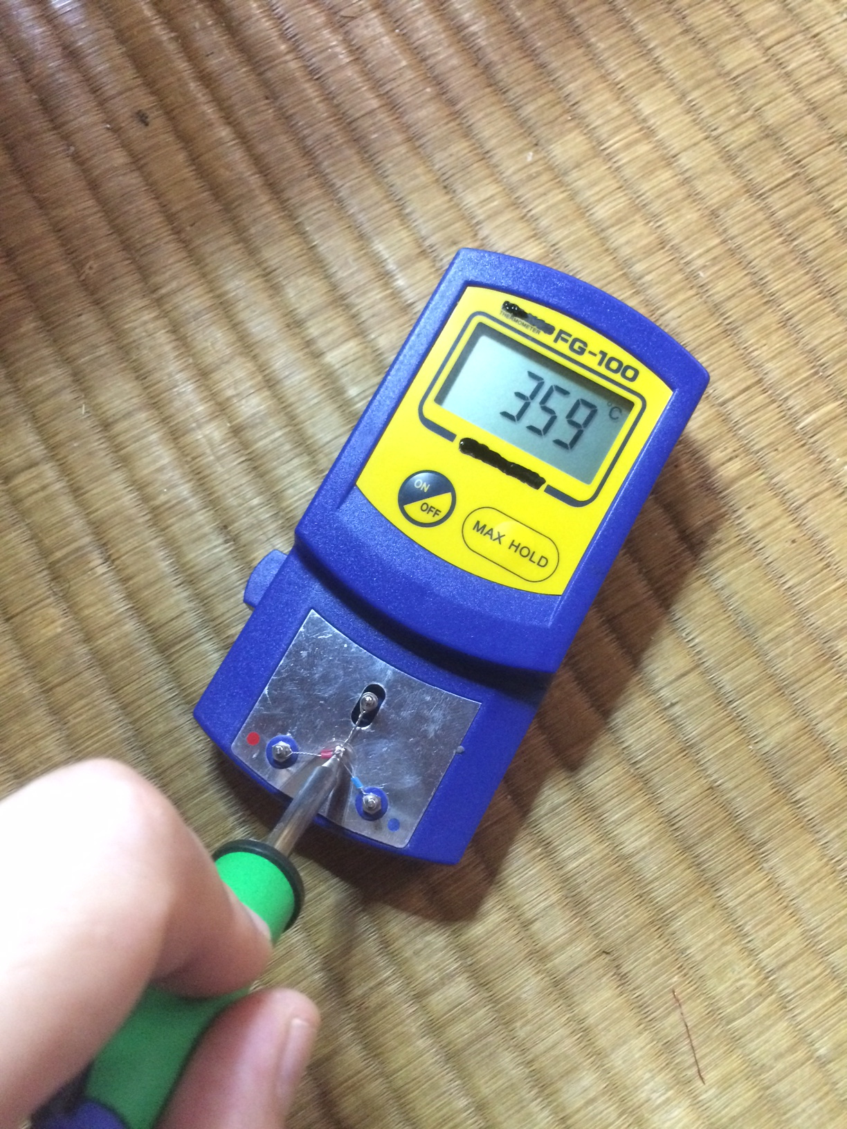
T12-D12 Tip
It comes with a set of 10 K-type thermocouples, in order to insure good heat transfer the soldering iron tip should be wet with solder when you measure the temperature. This unfortunately means the thermocouple can get mucky pretty quickly which is why it’s a replaceable part.
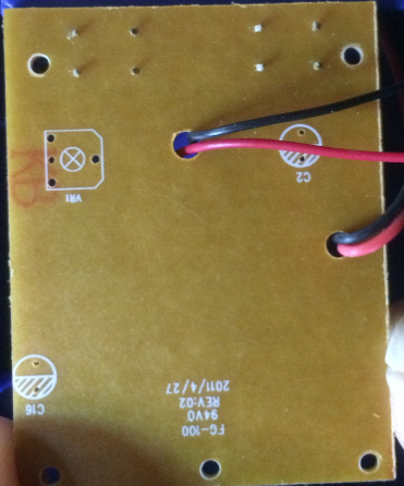
Obviously I’ve also taken the device apart too. Below you can see a couple of pictures of the PCB. It uses a single sided PCB with a die on PCB blob. I’m guessing this is a generic temperature sensing IC.
It’s interesting that the PCB has a soldermask, this seems to be a more recent trend with these ultra-cheap single sided PCBs which are commonly used in toys and other low cost products. If you’d like to buy this, I have it in my shop, with the Hakko branding removed. By purchasing from me you support further hacks. In particular I think it’s likely that you add a calibration pot (VR1 on the silk) and fahrenheit mode for people of this disposition.