Quanterix
This post previously appeared on the substack.
Quanterix was formed in 2007 with a focus on building a “single molecule” detection platform with a focus on proteomics applications. They raised a total of $533.33M and exited via IPO in 2017.
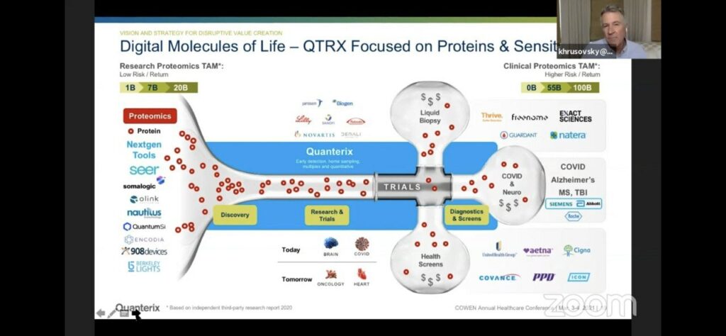
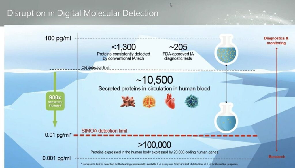
They position themselves as being very high sensitivity, for diagnostics applications. So (as they suggest) you have pretty much every other current and next-gen proteometics player working on “Research Proteomics”, then Quanterix coming in with high sensitivity on the Simoa platform which would be applied to diagnostics:
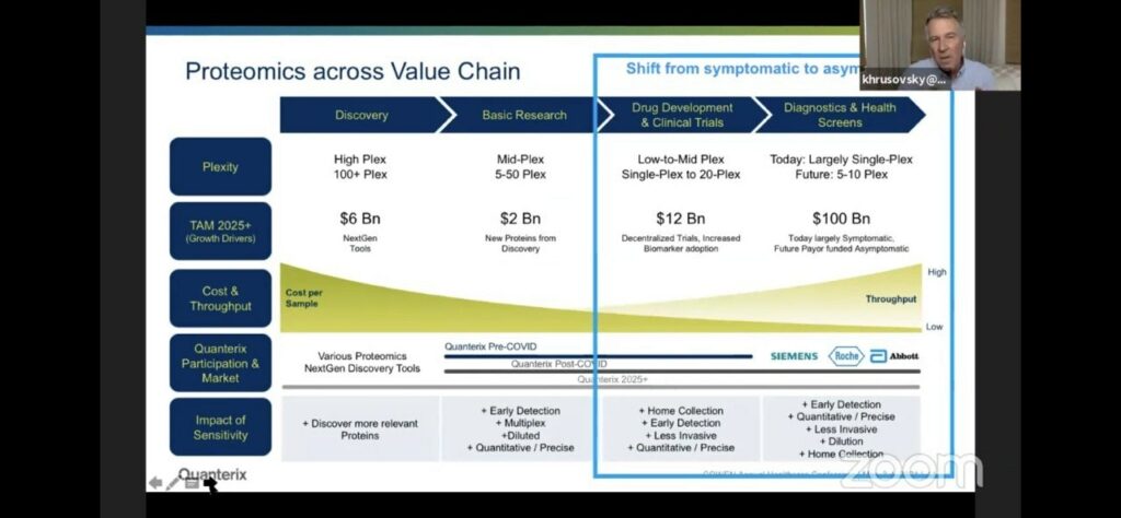
Which of course is where they suggest the big money is:
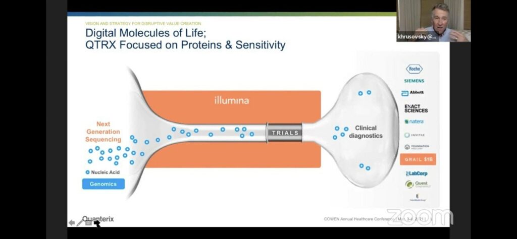
They draw a slightly awkward parallel to Illumina/genomics. Where Illumina make the discovery platform, but the bigger market is likely diagnostics. The analogy is awkward of course, because the Illumina platform often gets used both for discovery and for diagnostic applications [1]. Whereas in Quanterix’s case they’re suggesting that different platforms will be used for discovery and diagnostics.
Of course none of this really tells us much about the nuts and bolts of the Quanterix Simoa approach. But you can find a video here which discusses it in some detail.
Essentially what Quanterix are doing is single molecule ELISA.
In the traditional ELISA approach you have an antibody which binds to an antigen (some protein of interest). Then you have a second antibody, which binds against this first antibody with a linked enzyme. After washing off any unbound antibodies, this enzyme can be used to process a substrate into a product that shows fluorescence. So, you get a kind of amplification reaction, where a single antigen generates thousands of fluorophores.
Quanterix mix this up slightly, by isolating antigens in wells. This means each well shows activity from only a small number (ideally single) antigen (target protein). But through the ELISA process each antigen will generate a large number of fluorophores.
This is therefore not single fluorophore imaging and this should be possible using standard cameras and optics. In DNA sequencing, this likely wouldn’t be termed “single molecule”. As using the same logic you could call Illumina sequencing “single molecule” in that each observation ultimately is sourced from a single molecule [2].
The Quanterix process is described in their 2010 Nature paper:
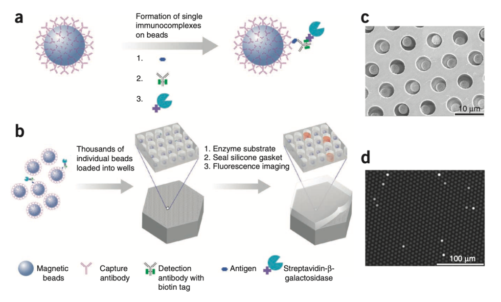
It makes sense that this could give increased sensitivity, as you have more sensing regions to work with, fluorescence is confined to femtoliter wells.
The single well occupancy is Poisson limited. Meaning that you’ll have some percentage of wells with single antigens (at most ~37%) and others with zero or more than one. But of course all wells are telling your something about the overall concentration of the analyte in the solution. What’s also neat, is while at the low end they operate in the digital domain (counting the number of wells with a single active enzyme) at the high end when all wells have one or more enzymes they can switch back to an analogue approach and just average over all intensities. This is part of what gives them higher sensitivity and dynamic range.
Using this process they claim they can measure down to 0.01 pg/ml, femtomole concentration:
This is great, but some public presentations suggest that in practice noise is somewhat higher in the 1pg/ml range, and that perhaps this is limited by issues relating to the processing of real samples:
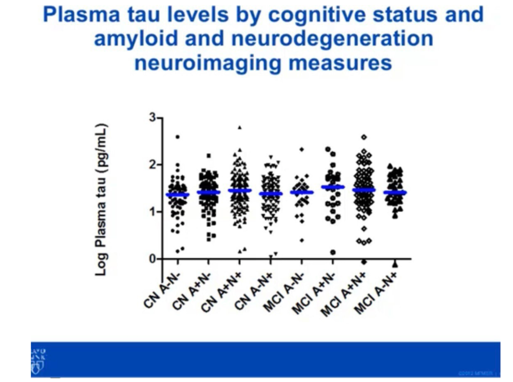
This would be more in line with Somalogic and other platforms.
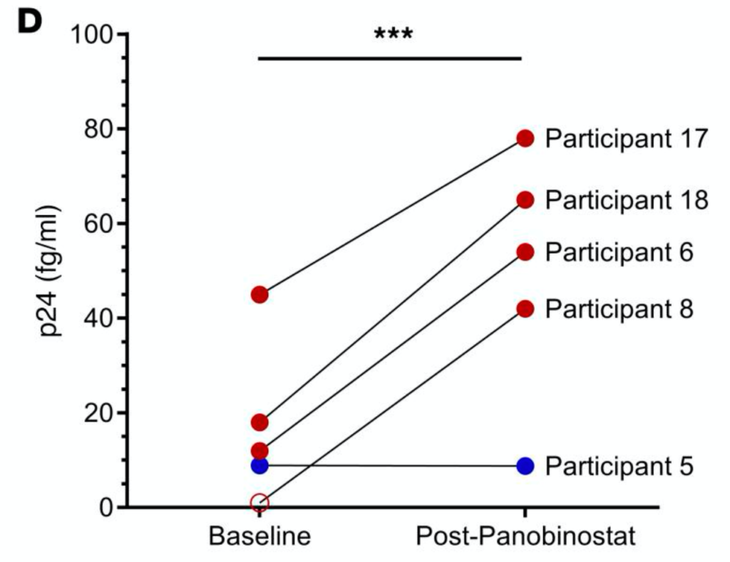
One report where the increased sensitivity does seem to add value is a article where they use the platform to look HIV drugs. In this case using qPCR is problematic (because HIVs mutation rate is so high), so looking at the p24 capsid protein appears to give a better estimate of viral load. Here (at low viral load) the Quanterix platform’s sensitivity appears to add value, showing sensitivity in the 10s of fg/ml range, right at Quanterix’s detection limit:
The Simoa platform appears to use ~216000 femtolitre wells (seemingly per analyte). In the diagram above these are shown as ~5 micron wells. Much bigger than Illumina’s current feature size, and mostly likely larger than used by Nautilus. So this is likely a modest fabrication problem, and I assume the fabrication costs looks somewhat similar to the Illumina BeadArray platform. I don’t have exact costs for these, but as they appear to be used by 23andme, which look to have ~50% margins, I suspect these chips cost <<$50.
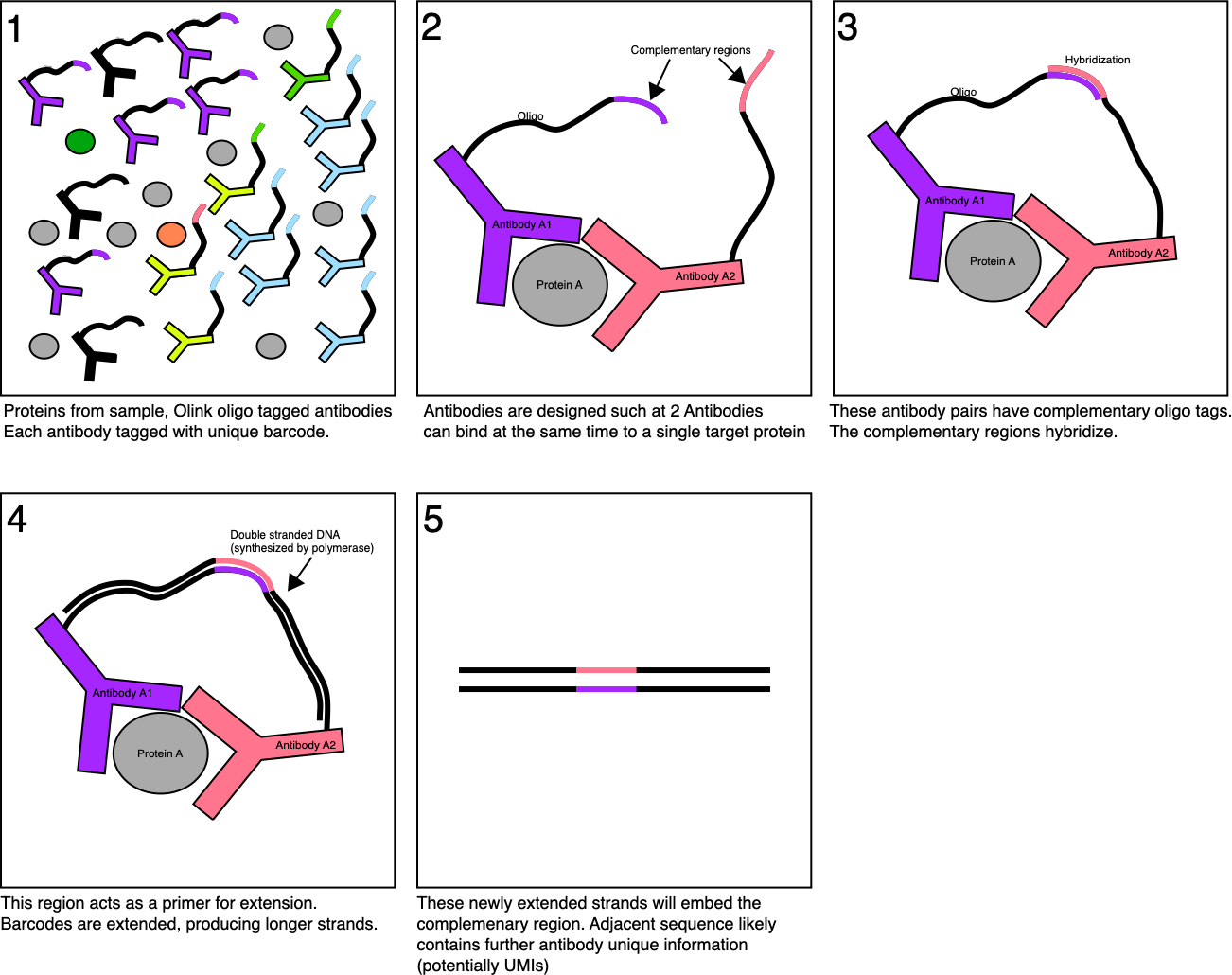
This is relatively cheap, and I suspect cheaper than some other approaches, but may still be too expensive for some diagnostic applications. For example, would this complete with Olink’s qPCR based platform? Which likely costs <$1 per sample.
Final Thoughts
Quanterix may have a platform that can provide higher sensitivity protein detection for some applications. There was one application where this appeared to be useful in practice, and potentially better than other next-gen approaches, but I’d need to dig further to come to any strong conclusion here. It seems likely that their sensitivity is at least “as good as” other cutting edge approaches.
What’s less clear is if their focus on diagnostic applications is realistic. In particular they suggest that approaches will be developed on other platforms (like Olink’s) and then transferred to Quanterix because it’s cheaper and more sensitive. But it’s not clear to me why you wouldn’t for example develop a test on the Olink PEA-NGS platform, and then transfer it to the Olink qPCR platform…
Finally, as I often do, I dug through the Quanterix glassdoor reviews. As always the negative reviews are more interesting than the positive, with numerous comments suggest that the company is “incredibly top heavy” and that “key positions in the company have been taken over by the CEO’s cronies”. “menu content drove everything here. It never mattered whether the assays worked of not. There was never a commitment to product quality”. This and a few of their public statements give me some concern.
But Quanterix are on the market, with 25.4M revenue in Q2. So to some extent, the academic publications and revenue should speak for themselves. I remain slightly more suspicious of their ability to break into major diagnostic applications. But like the idea that you can have a digital readout at the low end and scale to an analogue readout at the high end. This seems like a pretty neat idea.
- You could say that this is reasonable viral diagnostics, i.e. COVID19. Where the original sequence (and variants are detected) on the Illumina platform, but you use qPCR for diagnostics based on the reference sequence.
- In the case of Illumina sequencing, each cluster is grown from one template, in Quanterix thousands of fluorophores are generated by one antigen.


 RSS
RSS