Archive for the ‘Uncategorized’ Category.

esp8266 analogue input

esp1_analogue

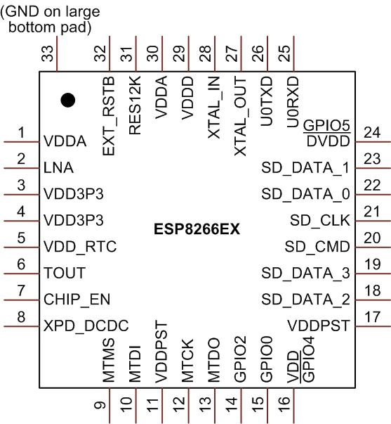
The esp8266 contains a 10bit ADC. There are apparently various issues, including instability when transmitting over Wifi, and the lack of a voltage reference. However it is usable. The analogue input is labeled “tout” on the pinout below:

esp8266_pinout

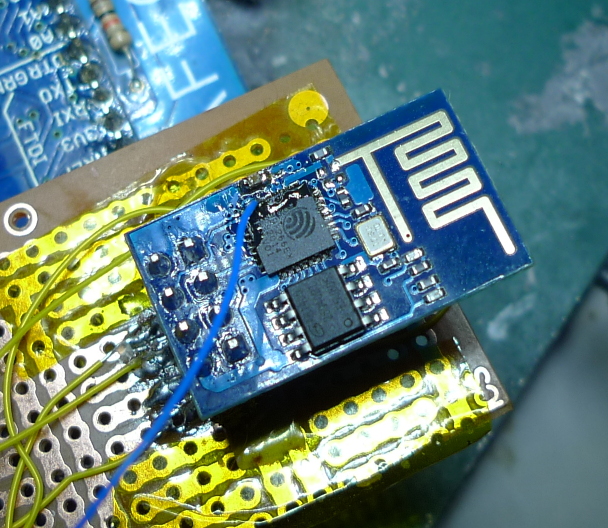
Unfortunately this isn’t broken out on the cheapest esp8266 boards (the esp1) but it’s possible to get access to it with some wirewrap wire and careful soldering (see image above).

The ADC input can then be read using some relatively simple C code as shown below. This code was adapted from an old version of the SDK (it doesn’t seem to be present in the current version).

I’ve also attached a complete working example that uses the function below: adc_test.tar

uint16 ICACHE_FLASH_ATTR adc_read(void) {
  uint8 i;
  uint16 sar_dout, tout, sardata[8];

  rom_i2c_writeReg_Mask(0x6C,2,0,5,5,1);

  // disable interrupts?
  SET_PERI_REG_MASK(0x60000D5C, 0x200000);
  while (GET_PERI_REG_BITS(0x60000D50, 26, 24) > 0); //wait r_state == 0
  sar_dout = 0;
  CLEAR_PERI_REG_MASK(0x60000D50, 0x02); //force_en=0
  SET_PERI_REG_MASK(0x60000D50, 0x02); //force_en=1

  os_delay_us(2);
  while (GET_PERI_REG_BITS(0x60000D50, 26, 24) > 0); //wait r_state == 0
  read_sar_dout(sardata);

  // Could this be averaging 8 readings? If anyone has any info please comment.
  for (i = 0; i < 8; i++) {
    sar_dout += sardata[i];
  }
  tout = (sar_dout + 8) >> 4; //tout is 10 bits fraction

  // I assume this code re-enables interrupts
  rom_i2c_writeReg_Mask(0x6C,2,0,5,5,1);
  while (GET_PERI_REG_BITS(0x60000D50, 26, 24) > 0); //wait r_state == 0
  CLEAR_PERI_REG_MASK(0x60000D5C, 0x200000);
  SET_PERI_REG_MASK(0x60000D60, 0x1); //force_en=1
  CLEAR_PERI_REG_MASK(0x60000D60, 0x1); //force_en=1
  return tout; //tout is 10 bits fraction
}

UPDATE: There’s also a system_adc_read function in the library symbols, I’ve not used it but it could be worth looking at.

This is a continuation of my notes on the esp8266 microcontroller, you can find a complete list of my esp8266 posts here

esp8266 notes summary

I’ve written a bunch of posts on the esp8266. This post is intended to summarize them, and I’ll update it as I add new content. All the code examples are designed for use with the open SDK available here.

SDK Investigations

Installing the SDK and basic examples
Notes on the 0.9.5 SDK, and rough installation notes
Looking at library symbols
How the SDK runloop works
Missing sscanf

Hardware

Module types available
Initial notes on programming/using the esp1

Wifi and TCP/IP

Access point mode
Wifi connection issues
Listen for incoming TCP/IP connections

Interfacing

UART (RS232) usage
GPIO Input
Analgoue Input

Internal peripherals

Internal flash storage
Sleep modes

My board designs

XBee carrier board
Programmer interface
Watch design
Olimex Design (not mine)

MSP430Watch2 – Barometer and Wifi (PCB Design)

msp430watch2_1

msp430watch2_2

A long while ago, I played with an hacked together watch, based on the msp430. Recently I’ve been playing with a few interesting parts, the esp8266, an interesting I2C LCD and a cheap barometric sensor.

I decided to throw all these components together in a watch layout, just for fun! The PCBs are now out to fab and I’ll update this post when I’ve built everything up. I’m not sure I’ll actually place the esp8266 and if I do, for any kind of sensible power consumption it would need to be off most of the time.

The schematic is below, and you can also find everything on github here.

msp430watch2

Notes

The switch used:
switch

Other footprints are from the Kicad libraries.

BMP180 Barometric Pressure Sensor

BMP180

I pick the module above up on ebay for about 2USD shipped. I figured at that price it would be interesting to pay around with. As a first step I attached it to a bus pirate v4 to see if I could get some basic readings, this post contains my notes on reading the temperature from the device. It should be pretty easy to modify this for pressure readings. The bus pirate setup looked like this, pretty standard I2C connection:

busp_bmp180

For these tests the initial, I2C setup was as described here. Both the 3.3V and VCC lines on the module needed to be connected to the 3.3V supply. The output of the bus scan was as follows:

I2C>(1)
Searching I2C address space. Found devices at:
0xEE(0x77 W) 0xEF(0x77 R)

The address values above are correct according to the datasheet. After the initial scan I shorted the power and ground lines (clever me!) and the magic smoke was released from VR2. Looks like I’ll be replacing that. However, surprisingly everything still works.

Before you can do much with the BMP180 you need to read the calibration values from its EEPROM. These start at EEPROM address 0xAA and are described on page 15 of the datasheet. Here’s an example of how you’d read the first calibration value, which is stored at indexes 0xAA and 0xAB with the bus pirate. Writing 0xAA to 0xEE selects the register. Reading from 0xEF then reads the register bytes. It looks like it auto-increments too:

I2C>[0xee 0xaa]
I2C START BIT
WRITE: 0xEE ACK
WRITE: 0xAA ACK
I2C STOP BIT
I2C>[0xef rr]
I2C START BIT
WRITE: 0xEF ACK
READ: 0x1F
READ:  ACK 0x98
NACK
I2C STOP BIT

Here are the register values I read on my device, with the values required for temperature conversion decoded as decimal.

NAME: REG IDX  : VALUES    : DEC
AC1 : 0xAA 0xAB: 0x1F 0x98 : 8088
AC2 : 0xAC 0xAD: 0xFB 0x9E : -31646
AC3 : 0xAE 0xAF: 0xC7 0x17 : -18199
AC4 : 0xB0 0xB1: 0x81 0x51 :
AC5 : 0xB2 0XB3: 0x62 0x3A : 25146
AC6 : 0xB4 0xB5: 0x3B 0xB2 : 15282
B1  : 0xB6 0xB7: 0x19 0x73 :
B2  : 0xB8 0xB9: 0x00 0x2A :
MB  : 0xBA 0xBB: 0x80 0x00 :
MC  : 0xBC 0xBD: 0xD1 0xF6 : -20982
MD  : 0xBE 0xBF: 0x0A 0xAB : 2731

As I understand it writing 0x2e to register 0xf4 selects temperature reading:

I2C>[0xee 0xf4 0x2e]
I2C START BIT
WRITE: 0xEE ACK
WRITE: 0xF4 ACK
WRITE: 0x2E ACK
I2C STOP BIT

The temp can then be read by writing 0xf6 to select the MSB (and 0xf7 for LSB), and then reading from register 0xef:

I2C>[0xee 0xf6]
I2C START BIT
WRITE: 0xEE ACK
WRITE: 0xF6 ACK
I2C STOP BIT
I2C>[0xef r]
I2C START BIT
WRITE: 0xEF ACK
READ: 0x59
NACK
I2C STOP BIT

I2C>[0xee 0xf7]
I2C START BIT
WRITE: 0xEE ACK
WRITE: 0xF7 ACK
I2C STOP BIT
I2C>[0xef r]
I2C START BIT
WRITE: 0xEF ACK
READ: 0xC3
NACK
I2C STOP BIT

The above reads show a value of 0x59 for the MSB and 0xC3 for the LSB. Converting these to a single decimal gives 22979. Page 15 of the datasheet describes how to convert the temperature and the calibration values into a reading in Celsius. I threw this all into bc:

x=(22979-15282)*(25146/(2^15))
y=(-20982*(2^11))/(x+2731)
z=x+y
((z+8)/(2^4))/10
5.873557310957312033718

So approximately 6 degrees. Given it’s about 4 degrees outside in Tokyo, and I don’t have the heating on that seems about right!

If I decide to move forward with this part I’ll likely attach it to a dedicated microcontroller now I have basic I2C comms working.