INHECO 96 Chick Brooder

Overview

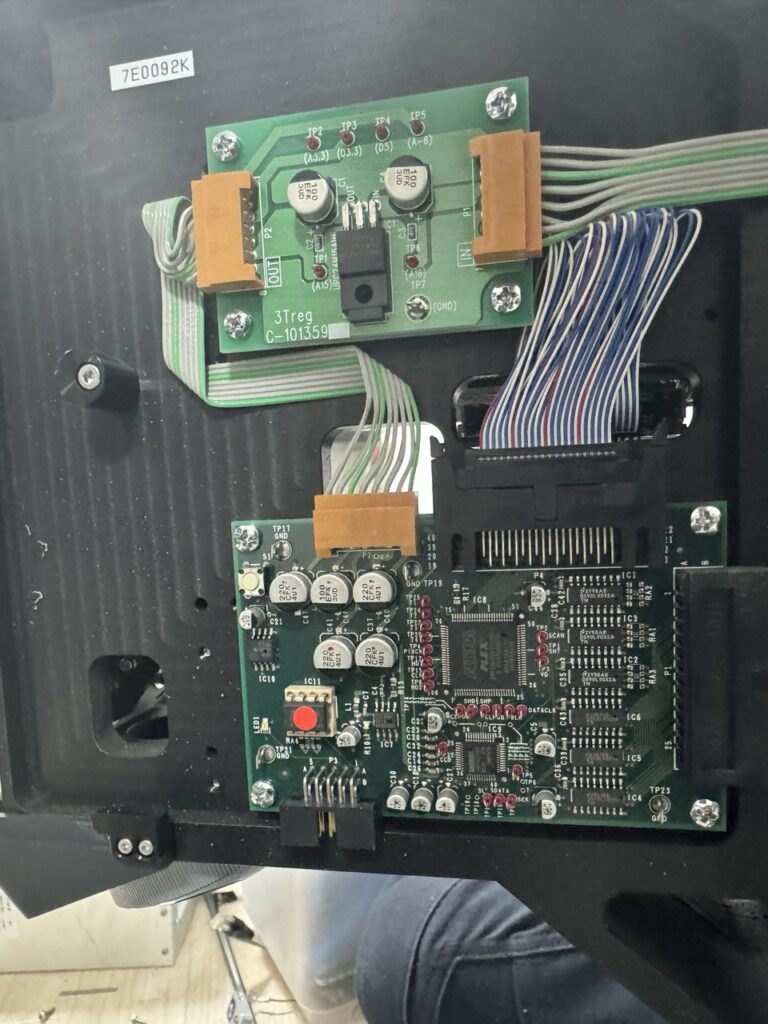
The Inheco Control 96 is an OEM unit built around a Watlow Series 96 PID controller and a Watlow LSTW driver module, housed in an Inheco-branded chassis. Originally designed for TEC/Peltier temperature control in laboratory equipment (e.g. the Inheco CPAC Ultraflat for heating Eppendorf tubes), it can be repurposed as a general-purpose temperature controller.

This writeup documents repurposing one such unit to drive a Kotatsu heater element (~100V rated, operated at 30–40V) as a brooder heater for day-old chicks. The unit was acquired second-hand and arrived with a PIC microcontroller attached to the RS232 port and the controller in a misconfigured/locked state.

Reference also: 41j.com Inheco Control 96 Notes — confirms the LSTW is an undocumented OEM module, likely an H-bridge in the original TEC application, but in single-output configurations acts as a simple DC power switch.


Hardware

Watlow Series 96 PID Controller

  • 1/16 DIN panel mount PID controller
  • Universal input (thermocouple, RTD, process)
  • 4 outputs (configuration dependent on model)
  • RS232 serial communications on output 4 terminals (19, 20, 21)
  • Keys: ▲ Up▼ Down∞ Home/Infinity↺ Advance/Cycle
  • Firmware version on this unit: r7dL (visible in DIAG menu)

Watlow LSTW 1.5 Driver Module

  • Undocumented OEM module, not available on Watlow website
  • 8-terminal connector block
  • Functions as a DC power switch (not a true SSR)
  • Contains an IRF5305 P-channel MOSFET (55V, 31A rated) as the main switching element
  • Protection diode across input: originally B13 Schottky (30V, 1A — undersized)
  • Status LEDs: GRUN (green) = control input active, ROT (red) = output switching on

LSTW Terminal Pinout (as determined empirically)

PinsFunction
1–2Unknown / unused in this config
3–4Output to load (heater)
5–6Control input from Watlow 96 (24V DC signal)
7–8Connected to Watlow 96 rear center terminals (power/common)

The LSTW passes the supply voltage through to the load when the control signal is active — it does not have a separate mains input. Supply voltage = output voltage.

Kotatsu Heater Element

  • Rated 100V AC
  • Operated at 30–40V DC (sufficient for brooding temperatures)
  • Connected to LSTW output terminals 3–4

Thermocouple

  • Type J (blue/red wire, European IEC colour code)
  • Connected to Watlow 96 Input 1 terminals
  • Polarity sensitive — blue wire to negative terminal


Watlow Series 96 — Key Navigation

ActionKey Sequence
Home PagePress  briefly
Operations PagePress ▲ + ▼ together (~3 sec)
Factory PageHold ∞ + ↺ together for 6 seconds
Setup PageHold ▲ + ▼ together for 6 seconds
Enter a menuPress 
Change value / 
Confirm valuePress 

Some config settings appeared to be locked out at first. I’m not sure if I was just misunderstanding the config system or if I actually fixed this. There was a PIC connected to the RS232 input on the Watlow 96, this seemed to be processing a signal from a knob on the front of the unit. I disconnected this.


Configuring the Thermocouple Type

Accessing CIN1 (Calibration Input 1 Menu)

  1. Enter Config Page: hold  ▲+▼ for 6 seconds (it changes to one menu after 3s then again)
  2. Press  to navigate to CIN1
  3. Press  to enter
  4. Set the thermo couple type to H to K-type and J for J-type.

LSTW Diode Failure and Repair

What Happened

When attempting to supply ~40V DC to the LSTW input (to drive the Kotatsu heater at sufficient power), the protection diode B13 failed with visible smoke.

Root Cause

The B13 is a 30V, 1A Schottky diode — it is connected across the input terminals as a flyback/protection diode. Supplying 40V exceeded its 30V rating, causing it to fail.

The main switching MOSFET (IRF5305, P-channel, 55V/31A, TO-220 package) survived.

Repair

The blown B13 was removed. Unit was tested without it — functional short-term since the MOSFET is not switching at high frequency in this application, so flyback spikes are minimal.

Replacement diode found by scavenging: A D2S58 Schottky diode was recovered from scrap PCB.

D2S58 specifications: 80V, 2A — significantly better rating than the original B13 and well suited for this application.

Installation: Cathode (stripe) to positive input terminal. Solder across input terminals in same orientation as original B13.

The D2S58 replacement is an improvement over the original B13. If sourcing a new part, any Schottky diode rated ≥50V, ≥1A is suitable (e.g. 1N5819 at 40V is marginal; prefer SS34, 1N5822, or similar at 40V+).


Final Working Configuration

ParameterValue
Thermocouple typeJ type (J in CIN1)
Thermocouple wiringBlue = negative, Red = positive
LSTW control signal24V DC from Watlow 96 Output 1 (terminals top 3-pin block)
Supply voltage to LSTW~40V DC (Rigol DP832)
HeaterKotatsu element, connected to LSTW output terminals 3–4
LSTW protection diodeD2S58 (scrap), across input, cathode to positive
SetpointSet to desired brooding temperature (e.g. 35°C for day-old chicks)

Operational Notes

  • The GRUN LED on the LSTW indicates the 24V control signal is present and active
  • The ROT LED indicates the output is switching (heater powered)
  • If ROT is lit but no heat: check supply voltage is connected to LSTW and heater is connected to output terminals 3–4
  • ERR4 on the Watlow 96 = open sensor (thermocouple disconnected or broken) — check wiring at terminals 5, 6, 7
  • The controller PID will modulate output to maintain setpoint — allow time for auto-tuning to stabilise temperature control
  • A few degrees offset between reading and actual is normal with replacement thermocouples — a calibration offset can be added in the IN1 menu if accessible

M7 Wifi Camera Notes

I picked up a cheap Wifi security camera on Amazon, it uses a mobile app called “seeing”. Which appears to be that referenced at seeing.store.

No ports were open when scanned with nmap. Monitoring traffic on the router indicated it was talking to a remote server (appears to be on Alibaba’s cloud service):

traffic when streaming video: 
18:19:21.995059 IP 192.168.8.191.36198 > 47.79.82.123.443: Flags [F.], seq 228080, ack 6579, win 6169, length 0
18:19:21.998765 IP 47.79.82.123.443 > 192.168.8.191.36198: Flags [F.], seq 6579, ack 228080, win 831, length 0
18:19:22.671581 IP 192.168.8.191.36200 > 47.79.82.123.443: Flags [S], seq 4002814628, win 29200, options [mss 1460,sackOK,TS val 4294938745 ecr 0,nop,wscale 3], length 0

With some more fiddling it appears that the cloud service coordinates with the phone/camera but if they are on the same network the camera will stream directly to the phone:

8:52:29.753976 IP navas-iPhone.lan.49936 > 192.168.8.191.10666: UDP, length 48
...
18:52:29.841608 IP 192.168.8.191.10666 > navas-iPhone.lan.49936: UDP, length 1332
18:52:29.841943 IP 192.168.8.191.10666 > navas-iPhone.lan.49936: UDP, length 1332

Whatever communication the phone coordinates via the cloud appears to open up a UDP port on the camera. It first sends a packet with a payload of “dummy”:

Which the camera seems to echo back:

The phone then sends a more complex binary payload:

The camera then replies with some clear text:

The phone sends some more binary data to setup the stream… I was able to replay the initial packet from a PC and receive the clear text reply. But this only works if the port has been opened via the phone first.

With no clear routes into the camera via the network I pulled it apart. The camera uses a AllWinner IP Camera SoC. I tried probing all the pads labelled RX/TX for a serial interface but didn’t have any luck here.

So, dumped the flash next.

Via a raspberry pi using: sudo flashrom -p linux_spi:dev=/dev/spidev0.0,spispeed=500K -r m7_firmware.bin

The camera appears to use an OpenWRT fork called Tina Linux. eGON header found at beginning of flash, indicating use of Allwinner’s built-in BROM and SPL bootloader. Bootargs suggest a serial console should be present.. so some more hunting may reveal it.

That’s all for now!

More notes.

The pins on the top right of the board above labeled W-RX0 etc. show an interface which responds only during boot, here is some sample output:

[74648][D]PACKET_CMD_USER_DATA 5a 51 0 0 64 d2 66 24
[74649][D]PACKET_CMD_USER_DATA 5a 51 0 0 64 d2 66 24
[74724][D]ecd.poweron_qrcode 0, ecd.ring_power_off_valid_count 0
[75051][I]GET_WIFI_DATA(3) len: 9 1
[75052][I]GET_NET_INFO(25) len: 8 0
$>Welcome to Wlan Bluetooth Console Tools ......
$>[75202][D]PACKET_CMD_USER_DATA 5a 51 0 0 64 d2 66 24
[75202][I]GET_SOME_DATA(7) len: 8 0
[75724][D]ecd.poweron_qrcode 0, ecd.ring_power_off_valid_count 0
[75724][I][W0] wifi: 0 81 0 | 335 137, 0(0/0/0), 0(0/0/0) | 403 0 135 112002 1042001100 | 127320 67068 60252
[UMAC WARN] sta_add():360, scan entry >= 10, discard rssi lowest one
[UMAC WARN] sta_add():360, scan entry >= 10, discard rssi lowest one
[UMAC WARN] sta_add():360, scan entry >= 10, discard rssi lowest one
[76715][D]PACKET_CMD_USER_DATA 5a 51 0 0 64 d2 66 24
[76715][I]GET_WIFI_DATA(3) len: 9 1
[76724][D]ecd.poweron_qrcode 0, ecd.ring_power_off_valid_count 0
[76724][I][W0] wifi: 0 81 0 | 169 33, 0(0/0/0), 0(0/0/0) | 403 0 135 112002 1042001100 | 127320 67716 59604
[76733][D]PACKET_CMD_USER_DATA 5a 51 0 0 64 d2 66 24
[76738][I]GET_SOME_DATA(7) len: 8 0
[net INF] msg <wlan scan success>
[76888][D]NET_CTRL_MSG_WLAN_SCAN_SUCCESS
en1: Trying to associate with 94:83:c4:6c:98:2c (SSID='youanji1' freq=2412 MHz)
en1: Associated with 94:83:c4:6c:98:2c
en1: Clear keys to send no encrypt 4 of 4-way handshake
en1: WPA: Key negotiation completed with 94:83:c4:6c:98:2c [PTK=CCMP GTK=CCMP]
en1: CTRL-EVENT-CONNECTED - Connection to 94:83:c4:6c:98:2c completed [id=0 id_str=]
[net INF] msg <wlan connected>
[net INF] netif is link up
[net INF] start DHCP...
[77267][D]============= dhcp =============
[77269][D]ip:0.0.0.0
[77271][D]netmask: 0.0.0.0
[77274][D]gateway: 0.0.0.0
[77276][D]dns[0]: 0.0.0.0
[77279][D]dns[1]: 0.0.0.0
[77281][D]dns[2]: 0.0.0.0
[77283][D]dns[3]: 0.0.0.0
[77286][D]invalid ip
[77288][D]NET_CTRL_MSG_WLAN_CONNECTED
[77724][D]ecd.poweron_qrcode 0, ecd.ring_power_off_valid_count 0
[77724][I][W0] wifi: 0 81 0 | 182 48, 0(0/0/0), 98(1/0/0) | 403 0 135 112002 1042001100 | 127320 71412 55908
[77746][D]PACKET_CMD_USER_DATA 5a 51 0 0 64 d2 66 24
[77746][I]GET_WIFI_DATA(3) len: 9 1
[77761][D]PACKET_CMD_USER_DATA 5a 51 0 0 64 d2 66 24
[77761][I]GET_SOME_DATA(7) len: 8 0
[net INF] netif (IPv4) is up
[net INF] address: 192.168.8.207
[net INF] gateway: 192.168.8.1
[net INF] netmask: 255.255.255.0
[net INF] msg <network up>
[78221][D]============= dhcp =============
[78224][D]ip:192.168.8.207
[78227][D]netmask: 255.255.255.0

More Lasertec C130 Notes

I’ve been playing around a bit more with the Lasertec microscope. Looking at the literature Lasertec microscopes are often described as “Semi-confocal” this explains the lack of a galvo or anything that I could see that would deflect the light in X and Y:

So I suspect that the silver box at the top of the unit is the AOD and the detect (which is after all marked “slit detector”) is a silt detector!

I decided to pull out the CCD:

And cram a different sensor into the vacated void:

This for taking epi-illuminated images, this works somewhat reasonably:

LaserTec C130 Notes

I was pulling apart an old LaserTec C140 confocal microscope. Here are some pics! Here’s the main optical block:

There’s a photodiode, I assume with a pinhole and CCD sensor here:

On the other side of the unit there’s an FPGA.

Under the unit there’s a stepper (right) and a BL55 “Laserscale”.

I’ve been trying to figure out how all this fits together. The unit appears to be white light only, but I’m unclear on where the actuation is. It looks like everything is on the bottom of the unit. I guess the BL55 laser scale is used in combination with that stepper. But I’m not clear if there’s a full sub-micron precision XYZ stage here or if there’s something else going on. I was really expecting to see Galvos to scan the spot across the sample… hmmm.