Archive for August 2016

Marking intervals in gnuplot graph (with shading)

data

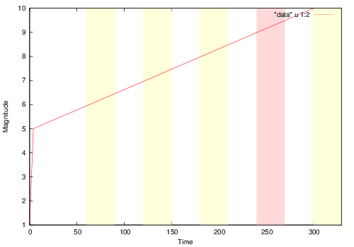
I needed to mark intervals on a gnuplot line plot different colors. Critically, I didn’t want to have to set the y start and end points (as you would if just drawing a rectangle). Turns out you can do this in gnuplot with a rect object and it’ll figure it out, such that it covers the graph area.

Example code is below (the “data” data file should contain x y datapoints 1 set per line in this example):

set terminal postscript eps color
set output "data.eps"

set xlabel "Time"
set ylabel "Magnitude"

set xrange [0:330]

set style rect fc lt -1 fs solid 0.15 noborder
set obj rect from 240, graph 0 to 270, graph 1 fc rgbcolor "red"
set obj rect from 360, graph 0 to 390, graph 1 fc rgbcolor "red"
set obj rect from 420, graph 0 to 450, graph 1 fc rgbcolor "red"
set obj rect from 540, graph 0 to 570, graph 1 fc rgbcolor "red"
set obj rect from 720, graph 0 to 750, graph 1 fc rgbcolor "red"

set style rect fc rgbcolor "yellow"
set obj rect from 60, graph 0 to 90, graph 1
set obj rect from 120, graph 0 to 150, graph 1
set obj rect from 180, graph 0 to 210, graph 1
set obj rect from 300, graph 0 to 330, graph 1

plot "data" u 1:2 with lines

The Wifi Doogle

esp_doogle_shop

I picked up these neat little esp8266 USB dongles from Shenzhen. If you’re interested, I have some in my shop too.

They incorporate a CH340g, 3.3v voltage regulator and esp8266. This creates a complete stand alone esp8266 stick, so you no longer need a USB serial interface or external voltage regulator. Almost all the pins are broken out too, which makes hacking projects on it easy.

It uses the serial RTS and DTR lines to enable running or flash update modes. This is a bit odd, but it does mean that you don’t need to switch jumpers to change modes which is nice.

Startup board in normal mode, you need to execute the following in python:

import serial
ser = serial.Serial('/dev/ttyUSB0',9600)
ser.setDTR(False)
ser.setRTS(True)
ser.setRTS(False)

You can then read data using python with “ser.readline()”. If there’s interest in these boards I’ll write up some further notes on how to work with the board using minicom.

I also stripped one of the boards down, this might prove helpful with debugging. It certainly helped me better understand how the boot mode was selected:

wifi_doogle

A PNG is here. And a SVG you can load in Inkscape with the board sides aligned so you can follow traces is here.

For reference, here’s some of the information from the original Chinese seller:

esp_doogle_orig


esp_doogle_orig3

For reference, to start the board in flash mode you can use the following (esptool.py does this anyway):

ser = serial.Serial('/dev/ttyUSB0',9600)
ser.setDTR(False)
ser.setRTS(True)
ser.setDTR(True)
ser.setRTS(False)

awk – print text between 2 identical markers in a file

Like this:

awk 'BEGIN{flag=0} /MARKER/{flag = !flag;next} flag' inputfule

Adapted from: here.

esp8266 SPI duplex transfers

I’ve been working with the esp8266 spi driver by MetalPhreak located here. One of the issues I’ve found is that duplex transfers (where you want to both send and receive at the same time) don’t work correctly. If you attempt to call spi_transaction specifying 8 dout_bits and 8 din_bits 16 clocks will be sent (IIRC a receive followed by a transmit).

The misunderstanding is likely down to the fact that the esp8266 has very little documentation. And the SPI registers aren’t documented at all. However the Arduino guys seem to have figured it out and it works correctly in the Arduino IDE board pack for the esp8266.

The trick is to set the SPI_USER register just so. There are 3 bits which control the direction of transfer SPI_USR_MOSI, SPI_USR_MISO and SPI_DOUTDIN (bits 27,28 and 0). In order to send and receive you need to set SPI_DOUTDIN and SPI_USR_MOSI but NOT SPI_USR_MISO. At least that’s what’s worked for me.

I made the following modification to spi_transaction to fix this. Change the line reading:

if(din_bits) {SET_PERI_REG_MASK(SPI_USER(spi_no), SPI_USR_MISO);}

to

  if((din_bits) && (dout_bits)) {
    SET_PERI_REG_MASK(SPI_USER(spi_no), SPI_DOUTDIN);
  } else {
    if(din_bits) {SET_PERI_REG_MASK(SPI_USER(spi_no), SPI_USR_MISO);}
  }

I’ll probably submit a pull request once I’ve made all the changes required for my project. But in this meantime this should work.